Construction
Because most of the sound-reactive and control circuitry on this project borrows heavily from my DJ Jacket, I’m focusing most of this section on the power electronics portion of the circuit.
Building a Transformer
Finding a transformer that suited my needs was no easy task. Most transformers have winding ratios that rank up to maybe the 1:8 range, but nothing close to the 1:20 range that I needed. This meant that I would have to wind my own transformer.
Selecting a Core
To create my transformer, I would first need a core. I decided to go with a E-core topology for this design because it provides an easy method for doing a lot of windings and offers very good coupling between the primary and secondary.
I was a little bummed to find that Digikey and Mouser have a paltry at best selection of ferrite inductor/transformer cores. I think these kinds of parts are sometimes best to order straight from manufacturers like Micrometals, but I was in a hurry and wanted to order them from a proper store. I ended up settling on Newark. They had a paltry but not nonexistent selection of E-cores.
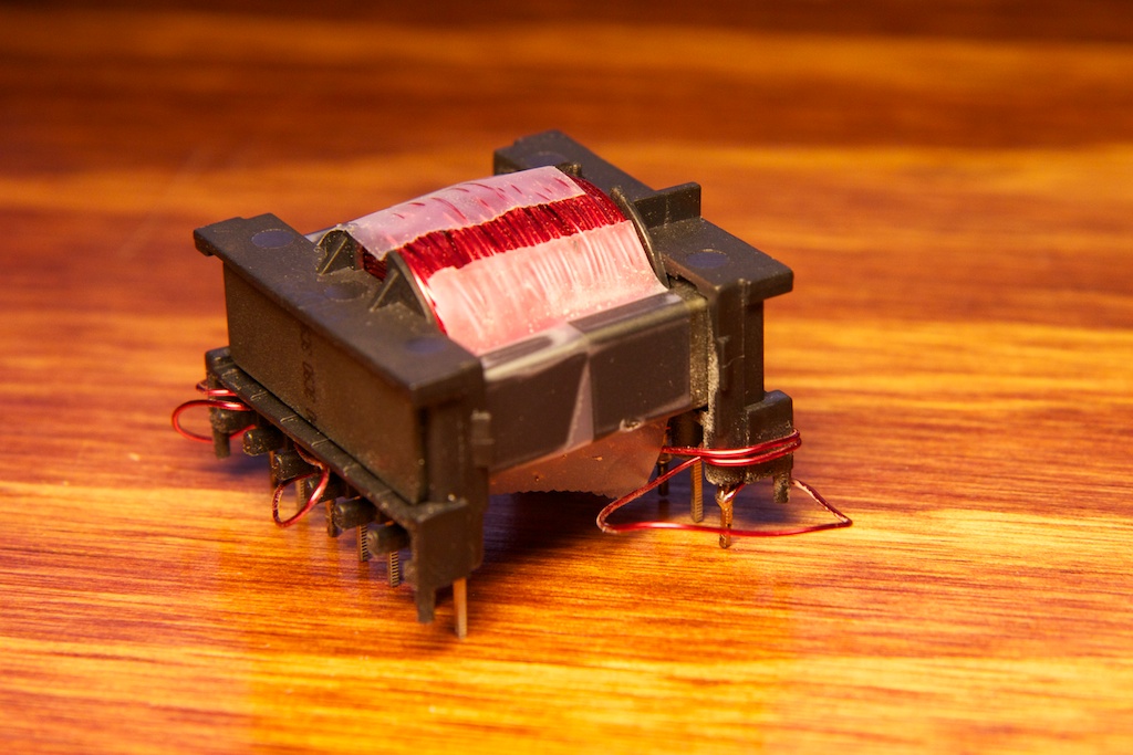
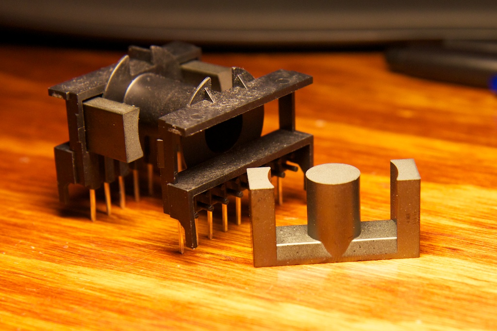
I was trying to find a mid-range sized transformer core because I didn’t want it to be too small like the puny EL wire transformers that I had before and suffer saturation issues, but I also didn’t want it to be too bulky to carry around. I really didn’t have much to choose from, so I just picked the ETD-29 size core and bought a bobbin to go with it. The idea is that you wrap the wire around the bobbin and then insert an E-core into either side.
Here’s a photo of a similar configuration with their ETD-39 model (it’s a little larger):
The bobbin makes winding the transformer much faster as you don’t need to feed the end of the wire through any kind of hole like you would with a toroid topology. The E-cores joined together should provide a lovely low reluctance path for the magnetic flux. If you’re interested in how this works, check out this post.
If you plan on buying transformer cores from Newark, let me warn you. Make sure you specify during check out that you want special packaging for your cores. I didn’t do this the first time and got this in the mail:
They were protected well from outside threats, but there was nothing protecting them from each other. Newark was very accommodating and sent me a new pack free of charge.
Winding the Core
Before winding the core, you have to determine how many windings you will need. I know that my secondary will need about 20x as many as my primary, but I don’t know what my primary needs.
If you remember from before, I need a primary transformer inductance of at least 170
![]()
H. Looking at the datasheet for my new core, I found a table on page 2 that specifies
![]()
with units of nH (my core is made out of the 3C90 material).
I had to look around to find out what
![]()
signified, but I found it to be a ratio of the inductance of the coil relative to the number of windings squared. It makes sense to determine it this way as you’ll remember from before that inductance is proportional to
![]()
. So let’s figure out how many windings we’ll need.
![]()
![]()
So I need 8.5 turns on my primary, and 20 times that on the secondary. Just to be safe (and when you take into account my previous blunder on transformer size requirements, I’m being very safe here), I rounded up to 15 turns for the primary. This works out to a required 300 for the secondary.
I used 24AWG enamel coated magnet wire to wrap my core. This is a fairly thick wire especially considering I’d be doing 300 turns on the secondary winding, but because I had so much extra space on the oversized core, this didn’t really present a problem.
I did end up falling a little short on space though. I ended up using just 270 or so turns on the secondary. This isn’t a huge problem, it just requires a slightly higher duty cycle to reach the desired output voltage.
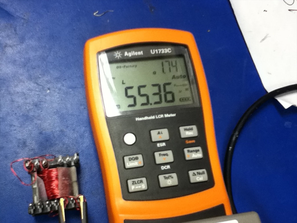
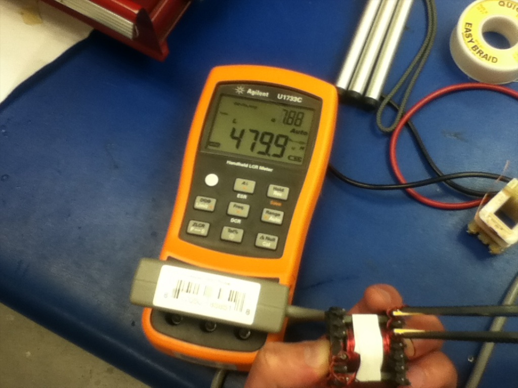
I borrowed the Agilent LCR meter again and took some measurements of my transformer windings. Here’s the primary:
This number is a little concerning. According to the data sheet, 55.4
![]()
H on the primary equates to:
![Rendered by QuickLaTeX.com \[\large \sqrt{\frac{55.45\mu H}{2.350\mu H}} = 4.85\]](https://ch00ftech.com/wp-content/ql-cache/quicklatex.com-e3b504a3d50a653d1553f2695b68d9c6_l3.png)
4.85 turns! That’s terrible! Okay, so it’s technically enough to work. Remember how I only technically need around 31.7
![]()
H on the primary? I’m getting well over that here. Further adding to that, I actually took all of these inductance measurements after taking the transformer off of my completed and functioning circuit, so it’s clearly not the end of the world. It still seemed odd that I was getting values so low.
That’s when I noticed this part of that table:
My cellophane tape clearly wasn’t applying anything close to 40 Newtons of force to the two halves. The small air gap between them was adding a huge amount of reluctance to the magnetic circuit and reducing my inductance by a large margin. Adding some tighter electrical tape helped out a lot:
And applying additional force with my hand gave me this:
Wow! that’s a big change. Using this number:
![Rendered by QuickLaTeX.com \[\large \sqrt{\frac{480\mu H}{2.350\mu H}} = 14.29\]](https://ch00ftech.com/wp-content/ql-cache/quicklatex.com-24f144993a05a09b8228e0864f9dcf03_l3.png)
14.29 turns is much closer to the 15 turns I was looking for. Sow how is this supposed to work? Did I assemble my core incorrectly? The answer is yes. Newark also sells a metal clip that holds the halves of the E-core together with quite a bit of force.
I knew these clips existed. I just didn’t quite realize how much force was needed. I guess that’s the one downside to an E-core over a toroid or other topology. If I were to design this again, I would use the clip, but for the time being, my transformer is fine.
Leakage
There is something of a science to winding transformers. The goal is to keep everything very neat and very tight. Why is this? Firstly, it enables you to fit more windings on the core. Secondly (and more interestingly), it’s to prevent leakage.
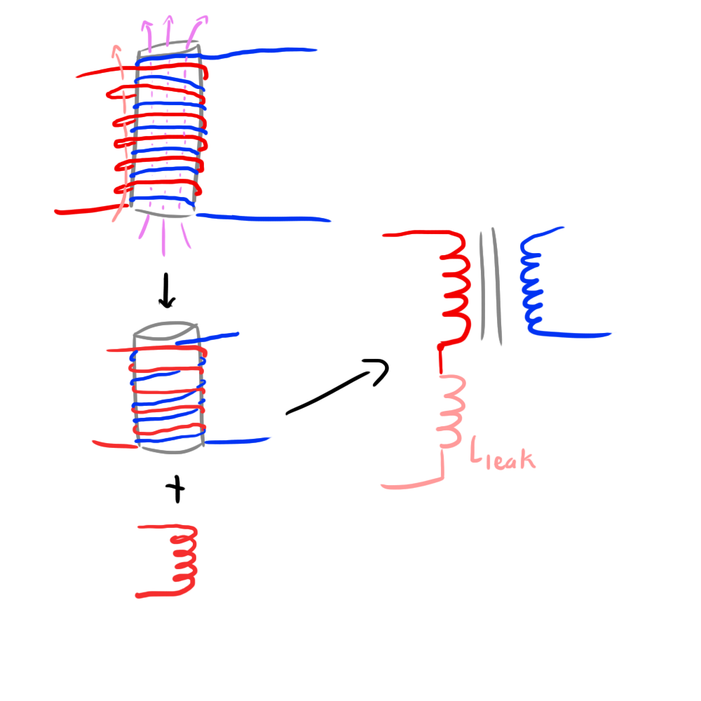
In an ideal transformer, all of the magnetic flux generated by the primary winding makes it to the secondary winding. In reality, some of this flux will leak out between the coils and cause the transformer to behave differently. If some of the flux from the primary winding doesn’t make it to the secondary, then you can think of that flux as contributing to the “leakage inductance” of the primary. Essentially, it’s like you have a totally separate inductor on the primary that in no way affects the secondary.
Here’s a doodle of an exaggerated example of leakage inductance that might help explain it:
Nobody is going to wind their transformer that poorly, but you can imagine how little gaps here and there on a normal transformer can contribute to magnetic fields leaking out (pink arrow) and not passing through the secondary. It’s important to note that in a lot of cases, the magnetic fields that leak out are not passing through the transformer core so the energy stored in them will be orders of magnitude less than the energy actually making it to the secondary winding.
Measuring the leakage inductance is easy. By shorting out the secondary winding, you can ensure that the current induced in the secondary winding will very nearly cancel out all of the magnetic field built up by the primary. This essentially negates your whole transformer and all that’s left is the leakage inductance that is not affected by the secondary.
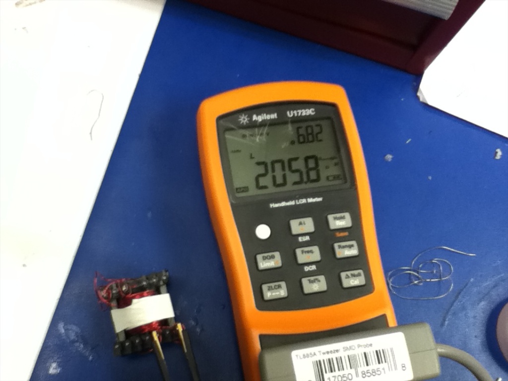
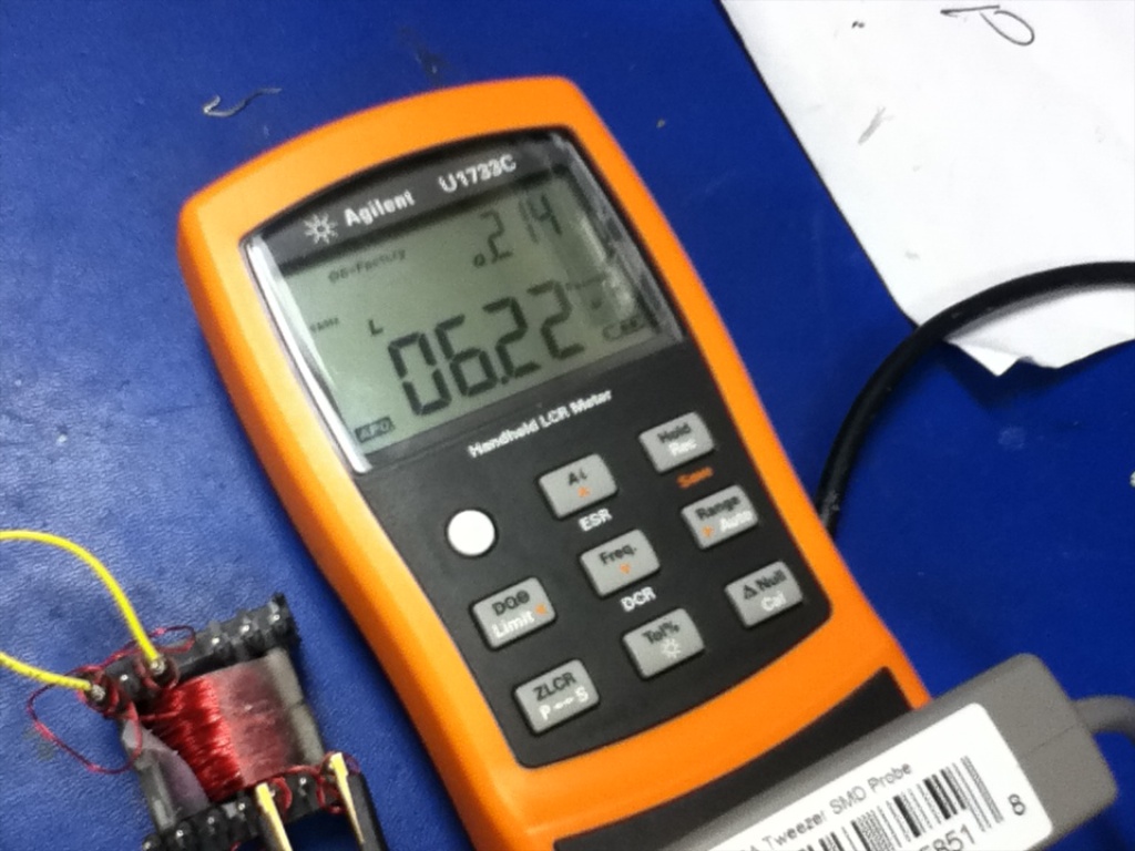
Attaching an LCR meter after shorting the secondary allows you to directly measure the leakage of the primary.
6.2
![]()
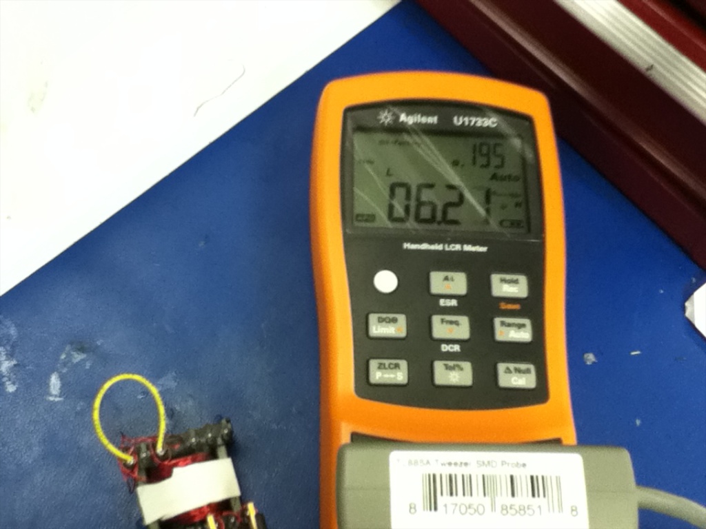
isn’t that bad. Now, here’s the really cool part. After tightening up the E-core halves in the above section using electrical tape (which increased my inductance by a factor of 4), I took another measurement of the leakage inductance:
Almost zero change. This is evidence that all of my leakage inductance is due to magnetic fields that are passing outside of my magnetic core as predicted and are unaffected by the changing core topology. SCIENCE!
Capacitors
There isn’t a whole lot to be said for the output cap. I just had to make sure I bought some that could take the voltage. I ended up using a few .01uF/200V caps in parallel.
Now we can finally move on to putting it all together!




yea there is a MUCH MUCH easier way to do this..
you take the standard inverter and the el panel and put a CDS photocell in series then take a standatd lm328 amplifier and hook the output to a bicolor LED and shine that on the photocell
DONE! i can give you schematics and stuff if you want
So you’re just talking about putting an adjustable resistance in series with the EL panel? I suppose that would work, but it’s not the most efficient way to do it.
Also, looking at a few datasheets, the maximum power dissipation though a CdS cell is around 100mW. If I were to use one on a panel, it might need to dissipate upwards of 7-800mW. It couldn’t take the heat. I suppose you could put a few in series, but that’s going to get pretty messy.
This solution might work in smaller loads like short EL wires though. Thanks for the tip!
When I first read your comment above I thought you were using the photocell to read the light from the EL panel and then reverse the voltage polarity when it detected maximum brightness, which should generate AC that would self-regulate to the right frequency to sustain that brightness level. But then when you mentioned LEDs you lost me! But would a feedback control mechanism like what I thought you meant actually work?
Matthew was recommending using a optoisolator as a variable resistance. The idea is that you could control current from a low-voltage circuit and not have to worry about the 120V blowing anything up.
You present an interesting idea, but I think it would end up being more trouble than it’s worth. The EL panel is a fairly “slow” material. It takes a few milliseconds for it to react to changes in current, so using its brightness in some kind of feedback system would prove difficult. To say nothing of the wiring/mechanical complications this would create.
>> I chose the 1N4148 which has a gate capacitance of just 4pF.
Not gate. Junction.
Since you were ordering from Digi-Key anyway, you could have purchased some BAT-41 Schottky diodes (19,000 in stock) . The BAT-41’s capacitance is 2pF, half of the 1N4148’s capacitance, and its forward voltage at 20mA forward current is 0.30 volts per diode, significantly less than the 1N4148’s 0.95 forward volts per diode.
Whoops, typo. Thanks.
I figured out my diode problem after I already made my order, so I had to use what I had on hand. Next time I’ll be sure to choose more wisely. Thanks for the tip!
while pouring over various patents on zinc sulfide phosphors i discovered reference to the color shift in el wire, my 555 based driver was a quick and dirty means of observing it myself and as an excuse to learn something about driving el wire… more of a first attempt using spare parts before devoting more time to designing a proper circuit rather than basing it off some simple dc to ac inverter circuit i found in the internet
along with the brightness being a function of frequency i found voltage had a similar effect but would cause the el wire to age faster than driving at a higher frequency would, and yes driving at higher voltages also caused my salvaged transformers to overheat and leak paraffin wax everywhere
Oh by all means, I think it’s great what you did, and it really helped me in my initial research! I was just making a point that in general, there aren’t too many resources available on EL wire and driving it properly.
there really arent, i had to resort to reading dozens of white papers and patents to figure everything out, my result was a working driver that was extremely inefficient, occasionally overheated and administered ~130 volt shocks when i wasn’t paying attention
ive also been working out some ideas on mixed frequency driving el wire to increase lifespan while making it brighter by rapidly switching between low and high frequencies at a rate where it would be brighter while impacting lifespan al little as possible
I also noticed the frequency shift.
Wonder if this effect can be used to make a variable spectrum microscope light?
For certain applications this would be handy indeed as if the wavelength shift is linear then you could image a sample at a range of multispectral frequencies rather than green or blue.
I like the Supertex HV852 for this as it draws under 5mA with small wires allowing a PIC to directly drive it and adjust frequency with a single drive lead and a capacitor.
So one 12F683 can run six separate EL wires, with Charlieplexing even more.
as far as i have observed there is only a single color shift at ~2000 hertz and i have not found any information to indicate there any more
it is far from linear and im not sure the amount of light would be sufficient for a microscope anyways
Pingback: Revisiting the EL Panel and the True Meaning of RMS | ch00ftech Industries
Pingback: Naw But Really Though…How Do You Power An EL Panel? | ch00ftech Industries
Pingback: I Should Give China More Credit | ch00ftech Industries
Pingback: The Color Mixing Christmas Light Project » Blog Archive » Pixel Mapping a Jogging Jacket
Pingback: Dimming EL Wire Dreamcatcher | ch00ftech Industries
Pingback: Sound Reactive EL Panel Dimmer (for real this time) | ch00ftech Industries
Pingback: Months of failure lead up to this EL panel dimmer that pulses to the music
Pingback: Months of failure lead up to this EL panel dimmer that pulses to the music | Daily IT News on
Pingback: Can I get this thing off my desk now? | ch00ftech Industries
Pingback: Soil Moisture Sensor | ch00ftech Industries
Pingback: More EL panel / el driver / el inverer hacking – pulsing | Reactive Lights
I found a great source for the EL panels. http://www.etsy.com/shop/lightkraft I looked all over and they are the least expensive in the US.. Most of their prices include the inverters (which are matched to each panel). Another good source is EL-WORKS http://www.el-w.com
Pingback: Bucking It Up » Geko Geek
https://ch00ftech.com/wp-content/uploads/2012/05/flyback11.png
Just saying, #schematicsthatlooklikefaces
What’s your take on this method?
http://www.enactiveenvironments.com/enabling/pwm-and-electroluminescent-smooth-dimming/
Hi,
How can I contact you? Email
Just click the email button at the top of the page!