CNC machine, Christmas gifts, and I’m a dope

Christmas time is always such a miserable, stressful lovely time at ch00ftech headquarters as I frantically scramble to finish all of the gifts that I’ve started for friends and family.  Unfortunately, in my haste, I haven’t been able to write up everything I did in detail, but I hope this post serves as a good summary of some of the stuff I did and what I learned.

CNC4UANDME

A few weeks into October, I tried to sign up for a new iPhone through T-mobile.  With credit card in-hand, I waited at the T-mobile store while my sales rep entered in my information, called over his manager, called T-mobile headquarters, entered in my information again, and generally struggled with the one task he was hired to do.

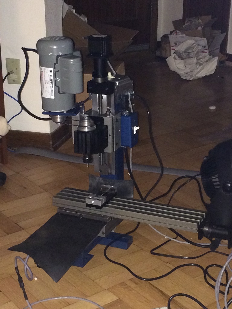
After 45 min, I was told that they would be unable to sell me that phone on that day. Unsure of why a phone store would still remain open when they are unable to complete the one transaction that they are in place to perform, I walked home.  Unsatisfied by the lack of gross irresponsible financial release that I had so thoroughly prepared for, I ordered a CNC machine.

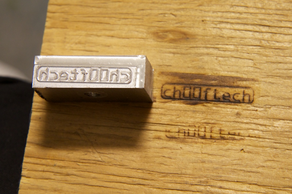
It wasn’t really an impulse buy though considering I have been thinking about buying a CNC mill for the past year or so.  I used to have access to one back in undergrad which is how I made the metal stamp that I used to make the burned wood image you sometimes see in this page’s header:

I really missed having the ability to make extremely precise objects out of a whole range of materials.  I know a lot of folks are going the 3D printer route, but I wanted to have the ability to make very precise and durable parts and enclosure for my projects out of a plethora of materials from wood and plastic to various metal alloys.

The mill I settled on is a Taig from Soigeneris. A lot of folks have told me that I should have built my own CNC, but I wanted this machine to be a tool that I use to complete projects, not a project in itself.  I ordered the mill with the optional rotary axis table, though I haven’t found much of a use for it yet.  I just thought that I might as well go all out.

It comes with the software CamBam and Mach3.  CamBam is a CAM or Computer Aided Manufacturing package.  Unlike CAD, CAM work involves actually deciding what kind of motions the tool has to take to carve out the shape you’re trying to make.  CamBam can do some 3D work, but it’s sometimes referred to as a “2.5D” solution as it mostly focuses on cutting and carving shapes out of flat stock. Mach3 is meant to control the CNC mill directly.  This software can read in GCode to control the CNC, or it can control it using direct input from the keyboard.  It apparently also has a number of built-in wizards for performing common tasks, but I haven’t had a chance to play with them yet.

The mill, the software, and a few collets and bits ran me almost exactly 3000.  <h1 style="text-align: left;">Early Projects</h1> One of the first things I did on my mill was carve a rod of aluminum into a 3D puzzle:  <a href="http://ch00ftech.com/wp-content/uploads/2013/12/IMG_1864.jpg"><img class="aligncenter size-full wp-image-4271" title="IMG_1864" src="http://ch00ftech.com/wp-content/uploads/2013/12/IMG_1864.jpg" alt="" width="1024" height="768" /></a>  It's not a whole lot to look at.  I got the design online and simply coded CamBam to carve some channels into some sections of 1/2" 6061 aluminum bar stock.  This stock was held easily in my mill's included vice grip.  This project could have easily been completed by a handmill, but I was still getting my bearings.  My second big project was a pinewood derby car.  I found the 3D model in the <a href="http://www.123dapp.com/smb-123D_Design/Indy-Car/1108784">catalog of parts</a> available for free in <a href="http://www.123dapp.com/">AutoDesk's 123D</a>.  <a href="http://ch00ftech.com/wp-content/uploads/2013/12/car.jpg"><img class="aligncenter size-full wp-image-4272" title="car" src="http://ch00ftech.com/wp-content/uploads/2013/12/car.jpg" alt="" width="996" height="827" /></a>  I tried to tweak the model a bit to align the wheels with the wheel channels carved into the standard pinewood derby block, but 123D Design's extreme lack of practical engineering features (it's more of an art program) made this very difficult.  I ended up having to drill new holes for the wheels' axels.  One of the hardest things to accomplish with a design like this is fixturing.  unlike 3D printing, CNC mill work requires some method of holding the stock material in place before cutting into it.  While it was easy to have a vice grip clamp down on the aluminum bar stock for the 3D puzzle, it's a little more difficult to pull off when basically all sides of the model are going to get sliced up.  After asking around, I heard one very simple suggestion that I wouldn't have expected to actually work.  Double-sided tape.  I started by carving out a flat channel in a block of wood using an end-mill. Because this was produced by the mill itself, it's guaranteed to be square and level relative to the mill's coordinates.  I then applied some two-sided tape to the pinewood block and stuck it down:  <a href="http://ch00ftech.com/wp-content/uploads/2014/01/IMG_1882.jpg"><img class="aligncenter size-full wp-image-4385" title="IMG_1882" src="http://ch00ftech.com/wp-content/uploads/2014/01/IMG_1882.jpg" alt="" width="1024" height="768" /></a>  After tweaking some of the car's dimensions in 123D, I exported as a .STL file and imported it into CamBam.  I don't have too many details of the settings I chose, but I did select "waterline-rough" as my method of cutting the 3D profile.  This means that it cuts down one level entirely before moving to deeper levels.  I made the mistake of doing this entire job with a 1/8" bit.  CamBam makes it fairly easy to do multiple passes with different sized bits, so I should have used a fatter bit to do a rough pass quickly and then moved to a smaller bit for more precise work.  Either way, it worked:  <a href="http://ch00ftech.com/wp-content/uploads/2013/12/IMG_1884.jpg"><img class="aligncenter size-full wp-image-4275" title="IMG_1884" src="http://ch00ftech.com/wp-content/uploads/2013/12/IMG_1884.jpg" alt="" width="1024" height="768" /></a>  <a href="http://ch00ftech.com/wp-content/uploads/2013/12/IMG_1885.jpg"><img class="aligncenter size-full wp-image-4276" title="IMG_1885" src="http://ch00ftech.com/wp-content/uploads/2013/12/IMG_1885.jpg" alt="" width="1024" height="768" /></a>  <a href="http://ch00ftech.com/wp-content/uploads/2013/12/IMG_1888.jpg"><img class="aligncenter size-full wp-image-4277" title="IMG_1888" src="http://ch00ftech.com/wp-content/uploads/2013/12/IMG_1888.jpg" alt="" width="1024" height="768" /></a>  Because my bit of choice had a cutting head that was narrower than its shank, I had trouble with long vertical sections.  Once the bit sank deep enough, the wider shank would rub up against the vertical surface of the wood.  For this reason, I manually destroyed the tail of the car with a pair of wire cutters to prevent the bit from damaging the rest of the model.  I did one more partial smoothing pass with a smaller vertical step size, and the model became pretty smooth.  <a href="http://ch00ftech.com/wp-content/uploads/2013/12/IMG_1889.jpg"><img class="aligncenter size-full wp-image-4278" title="IMG_1889" src="http://ch00ftech.com/wp-content/uploads/2013/12/IMG_1889.jpg" alt="" width="1024" height="768" /></a> <h1><span style="color: #000000; font-weight: bold;">Bitcoin Wallet</span></h1> I've been nerding out about Bitcoin for the past few months, and my dad has taken a cursory interest as well despite not actually purchasing any of his own.  For Christmas, I decided to give my dad some Bitcoin, but I wanted to find a fun way to deliver them.  <a href="http://bitcoin.org/en/">Bitcoin</a> is a digital currency.  I don't want to go into too much detail here, but the relevant portion of the system is that owning a Bitcoin consists of having the private key to a public address that someone has sent Bitcoin to at some point.  The private key is required to spend Bitcoin and the public address is required to receive them.  The kicker is that the public address is generated from the public key using a special algorithm, but there is no way to generate a private key knowing only the public address.  For the most part, public addresses are completely random strings of numbers and letters as the algorithm does a great job of scrambling the private key up so that it cannot be found from the public address.  Even small changes to a private key will change the public address entirely to a new random string.  Sometimes however, there's a chance that the public address will have a word or phrase in it that people might recognize.  If you guess enough private keys fast enough, the odds of finding a specific word or phrase in a public address goes up.  I thought it would be fun to give my dad a Bitcoin wallet with his name in the address.  This is commonly referred to as a "vanity address".  My dad's first initial and last name came out to seven characters, and since Bitcoin addresses are case-sensitive and I wanted to specify that, it took an incredibly large number of guesses to find the private key that worked.  Fortunately, I was able to use <a href="https://en.bitcoin.it/wiki/Vanitygen">OCLVanityGen</a> on my video card to guess a little over 18,000,000 private keys per second using my video card.  It was a little hard to set up, but thanks to some <a href="http://www.reddit.com/r/Bitcoin/comments/1s3wuh/safe_offline_qr_code_generator_for_printing/cdtvu2j">helpful folk on reddit</a>, I got it working.  <a href="http://ch00ftech.com/wp-content/uploads/2013/12/oclvanitygen.png"><img class="aligncenter size-full wp-image-4280" title="oclvanitygen" src="http://ch00ftech.com/wp-content/uploads/2013/12/oclvanitygen.png" alt="" width="677" height="342" /></a>  Half a trillion guesses later, the program spat out a private key and public address: <pre>1ACiuffovDAfshKeQKo7vo36KfDPxQGEgv</pre> I wrote the private key down somewhere safe and generated a QR code from the public address using an online QR code generator.  Looking for yet another way to utilize my CNC mill this holiday season, I decided to mill my dad a QR code keychain out of aluminum that he can use to accept Bitcoin into his new vanity address.  I imported the QR code into CamBam using the Draw>Surface>From Bitmap feature.  This will take a bitmap and assign a cutting depth based on the shade of grey in the image where darker pixels are cut deeper.  I learned that when importing low resolution images into the program, it will internally scale them up using a method that blurs the sharp edges of the QR code.  The end result is that every edge in the 3D surface ends up slanty:  <a href="http://ch00ftech.com/wp-content/uploads/2013/12/qrslanty.png"><img class="aligncenter size-full wp-image-4281" title="qrslanty" src="http://ch00ftech.com/wp-content/uploads/2013/12/qrslanty.png" alt="" width="663" height="215" /></a>  Scaling up the image in Photoshop where I could control the scaling method fixed this problem.  I then told CamBam to generate tool paths using a waterline method and a 0.049" bit.  I apparently had two such bits just...lying around.  I think I originally bought them to somehow cut holes in the enclosure of my <a title="The Bullet Counter" href="http://ch00ftech.com/2011/11/15/the-bullet-counter/">bullet counter</a> like...three years ago.  CamBam does not show you what your end result will look like, so I was unsure if a 0.049" bit would provide a QR code with sharp enough edges to be scanned (the bit is scarcely narrower than a single QR code pixel).  Drawing such a pixel in Eagle and remembering what I learned from the <a href="http://ch00ftech.com/2012/10/27/qr-clock/#display">QR Clock</a> convinced me that it was square enough for most scanners.  <a href="http://ch00ftech.com/wp-content/uploads/2013/12/toolpaths.png"><img class="aligncenter size-full wp-image-4282" title="toolpaths" src="http://ch00ftech.com/wp-content/uploads/2013/12/toolpaths.png" alt="" width="2560" height="1440" /></a>  With these toolpaths generated, I moved on to bringing it into the real world.  I started with a bar of 2"x1/8" aluminum bar stock that I picked up from <a href="http://onlinemetals.com">Onlinemetals.com</a>.  They're based in Seattle and don't charge shipping if you pick your order up at their warehouse.  Mounting the bar stock into my mill, I set about squaring off the surfaces:  <a href="http://ch00ftech.com/wp-content/uploads/2013/12/IMG_1989.jpg"><img class="aligncenter size-full wp-image-4283" title="IMG_1989" src="http://ch00ftech.com/wp-content/uploads/2013/12/IMG_1989.jpg" alt="" width="1024" height="768" /></a>  This wasn't entirely necessary for such a low-precision project, but I wanted to get rid of the roller marks and other blemishes that you can see on the stock in the above picture.  I used some parallels and 1/2" bar stock to set the piece so that its top surface sat just barely higher than the edge of the mill.  As it sat, there was probably 0.1mm of clearance between the mill and the vice as it shaved off the surface of the bar stock.  I would like to have given myself more wiggle room, but I couldn't find anything uniform enough to wedge in there to prop it up, so I just worked very carefully with the small gap.  With the surfaces all clean, I used an edge finder to program the mill's coordinates around the stock piece.  Used to working with larger bits and softer materials, my first attempt involved digging my bit in a solid 0.5mm and cutting at much too fast a pace.  This resulting in snapping my end mill off almost immediately.  You can see the hole here:  <a href="http://ch00ftech.com/wp-content/uploads/2013/12/broken-bit.jpg"><img class="aligncenter size-full wp-image-4284" title="broken bit" src="http://ch00ftech.com/wp-content/uploads/2013/12/broken-bit.jpg" alt="" width="543" height="375" /></a>  Fortunately, I had a backup bit, so I changed it to 0.05mm depth and slowed down the cutting speed too just in case.  This ended up taking several hours to get to the 0.5mm depth.  If I was running a factory, I would have chosen different settings, but as I was just trying to make a one-off without breaking any more bits, I was happy to wait.  Furthermore, Mach3 makes it easy to increase cutting speed as the job is progressing, so as I built up confidence, I carefully stepped up the speed to move things along.  <a href="http://ch00ftech.com/wp-content/uploads/2013/12/IMG_1994.jpg"><img class="aligncenter size-full wp-image-4285" title="IMG_1994" src="http://ch00ftech.com/wp-content/uploads/2013/12/IMG_1994.jpg" alt="" width="1024" height="768" /></a>  It was interesting to see the order in which CamBam decided to cut the grooves.  Even more interesting was the fact that by simply changing the depth of each cut, CamBam decided to start in a completely different section from where the bit was broken off.  <a href="http://ch00ftech.com/wp-content/uploads/2013/12/IMG_1996.jpg"><img class="aligncenter size-full wp-image-4287" title="IMG_1996" src="http://ch00ftech.com/wp-content/uploads/2013/12/IMG_1996.jpg" alt="" width="1024" height="768" /></a>  Unfortunately, the code wasn't scannable in this form, so I quickly moved on to painting it.  Two coats of flat black spray paint gave me this:  <a href="http://ch00ftech.com/wp-content/uploads/2013/12/flatblack.jpg"><img class="aligncenter size-full wp-image-4289" title="flatblack" src="http://ch00ftech.com/wp-content/uploads/2013/12/flatblack.jpg" alt="" width="1024" height="768" /></a>  Then some work with a piece of 80 and then 400 grit sand paper on a flat surface gave me this:  <a href="http://ch00ftech.com/wp-content/uploads/2013/12/sanded.jpg"><img class="aligncenter size-full wp-image-4290" title="sanded" src="http://ch00ftech.com/wp-content/uploads/2013/12/sanded.jpg" alt="" width="1024" height="768" /></a>  Finally, a hole for the keychain and a few layers of clear-coat:  <a href="http://ch00ftech.com/wp-content/uploads/2013/12/clearcoat.jpg"><img class="aligncenter size-full wp-image-4291" title="clearcoat" src="http://ch00ftech.com/wp-content/uploads/2013/12/clearcoat.jpg" alt="" width="1024" height="768" /></a>  The clear coat doesn't seem to stick too well to the aluminum, but it should provide some protection for the paint.  Regardless, my dad is pretty handy, and as long as the aluminum itself isn't seriously destroyed, refinishing it and returning it to this shape should be possible long into the future.  Let's just hope Bitcoin lasts that long. <h2>Earrings</h2> After the disaster that was my <a title="Light Up Earrings" href="http://ch00ftech.com/2013/10/08/light-up-earrings/">first pair of earrings</a>, I decided to re-make them entirely with new PCBs cut with my CNC and new enclosures cut out of plastic instead of Sculpey. <h3>PCB</h3> Using a CNC mill to cut PCBs is often called the "isolation method" as you're removing material to isolate separate traces on a solid sheet of copper clad PCB.  My CNC mill has a step distance of 0.0005" or 0.5 mil, so cutting the 10 mil traces that I was so proud of etching previously is trivial.  The hard part is finding a bit small enough.  Some of the gaps in this circuit are just a few mil wide, and it's difficult to find endmills with tips that are that small.  That's why most people use engraving bits.  These bits have ends that are pointed to some set angle and taper down to a point that is smaller than a mil across.  Presumably, you'd want a bit that tapers down to a point at the sharpest angle possible.  This will allow for the narrowest possible cuts.  What I learned looking around online however is that sharper bits will leave your traces with sharper edges that may peel up faster than the more gradually tapered ends produced by shallower angles.  Splitting the difference, I ordered a 30 degree and 60 degree bit off Soigeneris.  To generate the Gcode file necessary to cut the board, I used a free plugin for Eagle called <a href="http://www.pcbgcode.org/">PCB-Gcode</a>.  This software suite lets you select things like your cutting depth and isolation distance as well as the number of passes.  Technically, only one pass is necessary, but with such a narrow path cut between the traces and the unused copper on the board, it becomes fairly easy to accidentally form shorts.  Here are the settings I used:  <a href="http://ch00ftech.com/wp-content/uploads/2013/12/pcbgcode0.png"><img class="aligncenter size-full wp-image-4294" title="pcbgcode0" src="http://ch00ftech.com/wp-content/uploads/2013/12/pcbgcode0.png" alt="" width="1375" height="876" /></a>  <img class="aligncenter size-full wp-image-4293" title="pcbgcode" src="http://ch00ftech.com/wp-content/uploads/2013/12/pcbgcode.png" alt="" width="1375" height="876" />  A lot of the settings such as Z up and Z down are pretty self explanatory, but I had some trouble with epsilon and isolation.  Minimum isolation is supposed to tell the software how far to keep the bit away from the edge of your trace to guarantee that the bit's edge doesn't remove any of the trace in question. Epsilon is the gap to allow between subsequent passes.  This all makes a lot of sense for end-mills, but my bit tapers to an end that's essentially zero width, so neither of those settings make any sense.  I eventually decided to pretend that the width of the bit is its width at the surface of the copper clad which is just a fraction of a millimeter back from its tip.  Using the thickness of the copper, the angle of the bit, and a bit of trigonometry, I came up with the numbers you see above.  Some sources online reminded me that honing in these numbers is something of a trial and error process, so I'm sure I'll come up with better numbers as time goes on.  With these settings, the program spit out this doodle:  <a href="http://ch00ftech.com/wp-content/uploads/2013/12/Screen-Shot-2013-12-19-at-11.09.57-PM.png"><img class="aligncenter size-full wp-image-4296" title="Screen Shot 2013-12-19 at 11.09.57 PM" src="http://ch00ftech.com/wp-content/uploads/2013/12/Screen-Shot-2013-12-19-at-11.09.57-PM.png" alt="" width="914" height="736" /></a>  Each color represents a separate pass. You can see that in some areas only one or two passes could fit, but this is enough to properly isolate the circuit.  Sort of has a fun psychedelic look to it.  Just to see what would happen, I jammed a pen into the collet and ran this program:  http://youtu.be/BDpioV5Tkeo  Of course, when actually removing such a small amount of material, programming the height of the bit above the copper is absolutely critical.  I found one source that provided an interesting tip.  Just as the flutes of endmill bits are precisely manufactured, the shanks (the part that goes into the mill's collet) are also of very precise diameter.  By rolling a bit back and forth on the copper clad's surface and trying to pass it under a very slowly dropping engraving bit, I was able to determine the exact moment when the rolling bit would no longer fit. At this point, the height of the engraving bit off the copper clad is exactly known.  This can yield very accurate results and doesn't run the risk of breaking the engraving bit.  My first attempt with the PCB was a disaster.  For some reason, I got it into my head that 1/32" copper clad has 1/32" of copper on the surface when it's actually 1/32" of fiberglass with a 0.0014" of copper coating.  With this setting keyed in, my 30 degree bit dug a deep hole into the board before immediately snapping:  <a href="http://ch00ftech.com/wp-content/uploads/2013/12/IMG_5297.jpg"><img class="aligncenter size-full wp-image-4295" title="IMG_5297" src="http://ch00ftech.com/wp-content/uploads/2013/12/IMG_5297.jpg" alt="" width="1024" height="683" /></a>  This lesson cost approximately13.

My second attempt with the 60 degree bit worked much better:

And though it took a long time to finish, it was still faster and less messy than etching the PCB, and the end results were beautiful!

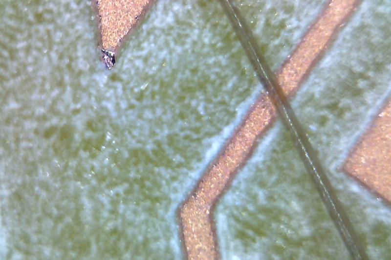
I really was impressed with the level of precision I was able to achieve.  Just look at this close up (human hair for scale):

And compare it to a similar trace etched with acid:

It looks a heck of a lot cleaner.  Now, the 10 mil traces definitely weren’t 10 mil across, but more trial and error with the isolation and epsilon settings will improve that.

Case

I’ll get back to how the PCB worked out, but now for the case.

For the new version of the earrings, I wanted a very simple case (box and lid) made out of some kind of durable semi-translucent material that cuts well on a CNC machine. I settled for a simple design that I whipped up in the cheap CAD suite ViaCAD and cut out of some “delrin” or acetal resin that I purchased from Online metals as 1″ round stock.

I might cover the CAD process in a later post, but the hardest part of making such a ridiculously tiny box (only 14mm across) was holding the damn thing in place.

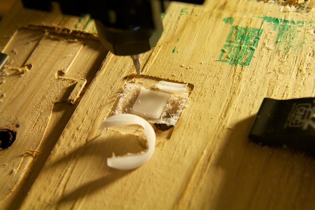
For the super thin lid, I was able to use the same method that I used for the pinewood car:

But I had no such luck on the much taller box.  Once it got down far enough into the form, the bit would always catch the box, rip it from its adhesive, and throw it across the room.  This happened five or six times before I decided that it just wasn’t going to work out.  I heard some suggestions to move to a stronger adhesive, but I decided to just clamp it down and do it right.

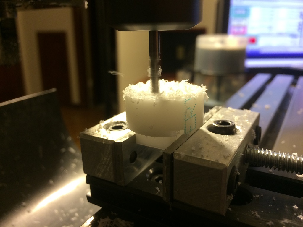
The adhesive method would have let me mill the entire object at once, but when clamping the raw material down, I needed to stop once the bit neared the vice grip so I could flip the piece around and start milling out the other side.  This was trivial from a mechanical perspective, but programming the mill to know the coordinates of the newly re-seated part was a lot more challenging.

Some parallels let me set the Z dimension, and an edge-finder up against the inner lip of the vice got me the Y dimension easily, but X presented a problem.  Because the part itself was overshadowed by the mass of stock I was cutting it from, there was no way to get an edge finder up against the part’s outer wall.  This image might make it a little clearer:

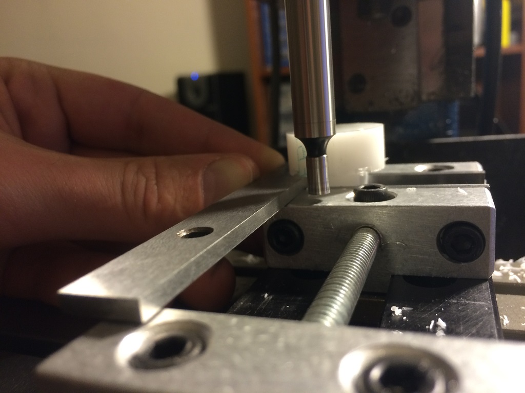
As far as the CNC was concerned, that part could be anywhere along the length of that vice.  I ended up sort of fudging it using a parallel and an edge finder like this:

This worked okay, but the tolerance stackup presented by the lack of rigidity of my hand and the softness of the delrin amplified by the length of the parallel caused one of my earrings to have a characteristic lip where the second half was milled just a few micrometers off center from the first.  This didn’t have any mechanical impact, but considering that these are more form over function, I was mildly upset. In the future, I might try making a custom tool for this.

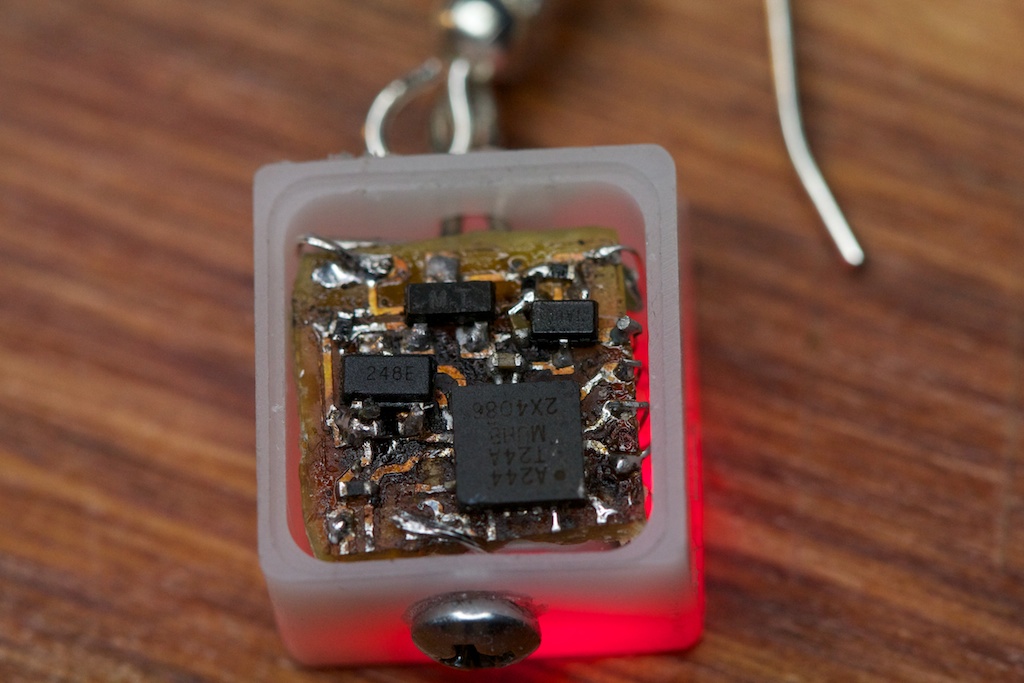
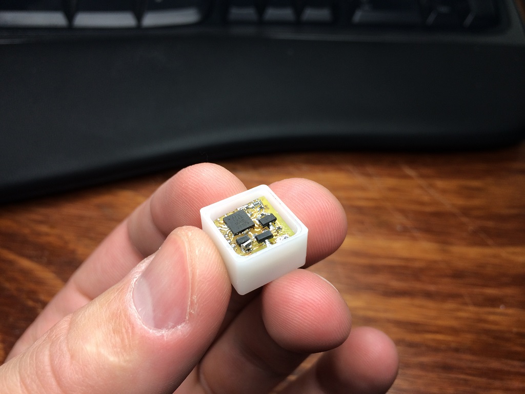
All setbacks aside, the final product turned out pretty well.  Here’s the case with the original circuit in it:

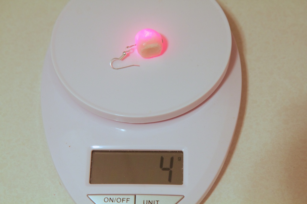
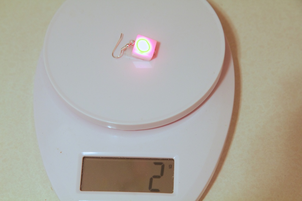
The thinner walls of the delrin cases made the earrings much brighter and smaller than their Sculpey counterparts:

And lighter too:

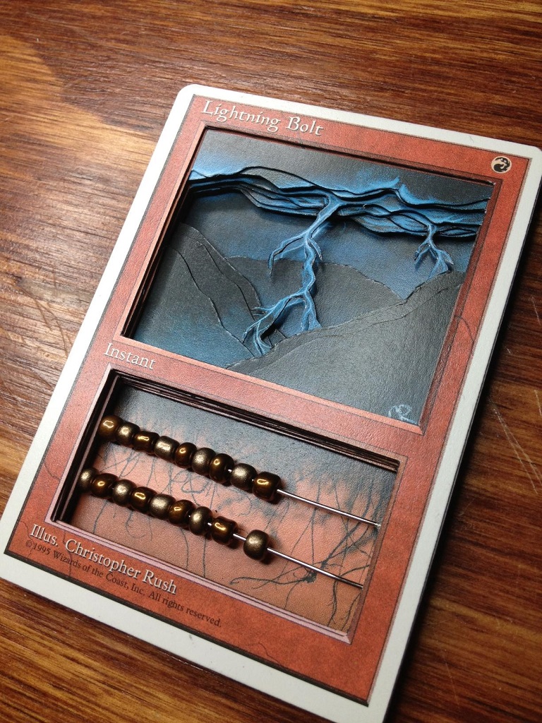
I made some other (poorly documented) improvements over the original design. The hole in the bottom was precision drilled with the mill which means that the little screw heads fit very snugly and almost snapped in place (a dab of super glue kept them there).  I attached the ear hooks to a steel loop of wire instead of the copper wire I used before.  The wire was the same stuff I used to make this:

Steel is more durable than copper, and it leaves me the option to use magnets to attach the positive charging terminals instead of alligator clips.  I was also happy to find that it can be easily soldered to copper to make the necessary electrical connections.

 I’m a dope

You might be wondering why the above pictures show my original circuit board getting loaded into the new delrin case after I spent all of this time re-making said board with the CNC machine.

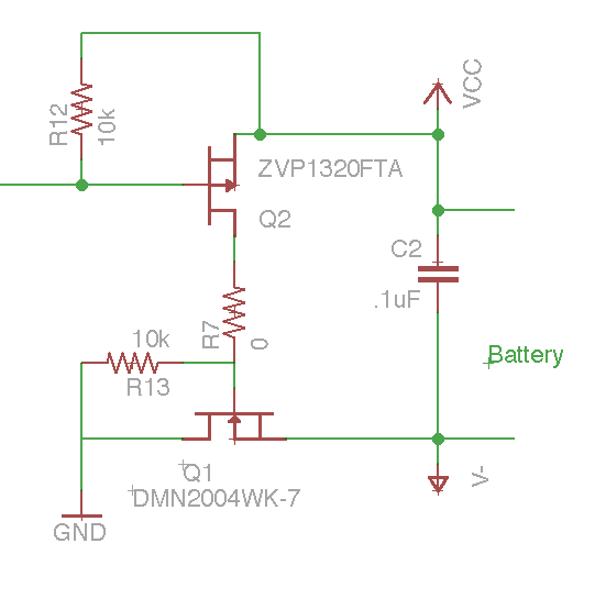
Well, there were some poor assumptions I made in the design of my original earring’s suicide circuit.  I ended up using this:

Despite the fact that R13 should actually be tying the gate and source of Q1 together (oops), this circuit worked exactly as advertised. When the trace leading off the left side of the schematic is disconnected, R12 shuts off Q2 which in turn stops providing charge to the gate of Q1 which then turns off and disconnects circuit ground from the battery.

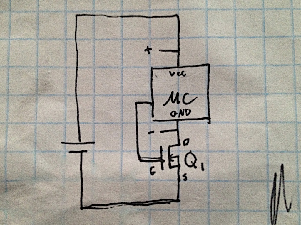
When I first designed this circuit, I had something like this:

Where I was driving the gate of the NFET directly from the output of the micro controller.  This failed because as the NFET shut off, the ground pin of the microcontroller rose, so it became impossible to exert a low enough voltage on the NFET to shut it off further.  The part would sometimes shut off, but most of the time, it settled into a half-on state where it continued to drain the battery.  Through some trial and error, I ended up adding both a PFET and some pull up/down resistors.

Though it was too late to undo what I had done, I was convinced by the end of that post that I didn’t need the PFET and could get away with a single NFET as long as I made sure to include the pull-down resistor on the gate.  After all, the issue I originally dealt with was exerting a low voltage from the micro controller.  If the pull-down pulled from an outside source, it should be trivial to turn the part off simply by switching the micro controller pin to a high-impedance input.

As it turns out, I was wrong.

Upon re-building this circuit with the CNC, I discovered that my new circuit exhibited the same half-on battery-killing problems that I experienced with my very first draft of the board despite the addition of the pull-down resistor and change to the firmware.  I wasn’t taking into account protection diodes.

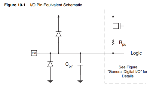
Page 54 of the ATTiny24’s datasheet includes this figure:

Pxn is the pin presented to the outside world.  You’ll note two diodes connected to this pin.  These two diodes are in place to protect the main portion of the IC from over or undervoltage conditions.  In other words, if the voltage on the pin drops below chip ground, the lower diode will source current from ground to this lower outside voltage to prevent the rest of the part from experiencing a negative voltage event.

In reality, these diodes are only really used for extremely quick pulses of high or low voltage (things like static shocks).  Because of their important role in protecting the chip, these diodes cannot be switched on and off and are always present even if the pin in question is configured as a high impedance input.

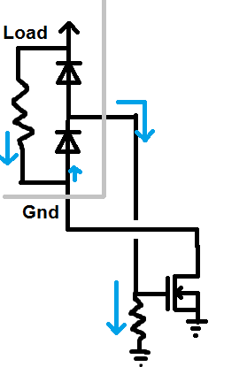
So while I was assuming that no current was flowing from the pin that was configured as a high impedance input, this diode was actually sourcing a fair amount of current into the gate of the NFET (and associated pull-down resistor) as the chip’s ground rail rose above the negative terminal of the battery.

Perhaps this image drawn with a laptop trackpad on an airplane will make it more clear:

(I can’t wait to get home)

In this doodle, the “load” resistor represent the current draw of the processor itself from its VCC to its GND pins.

I poured over this for a while, and I really don’t think anything can be done besides falling back to the NFET/PFET combo that I originally had.  That’s the only configuration where current leaking through these diodes does not prevent the FETs from turning off.

So the issue for me leading up to Christmas was that I needed to get these earrings done in a weekend, and I had just discovered the need for a PFET which I did not currently have in stock. This meant that I had to make everything happen with the original PCBs which were some of the ugliest circuits I’ve had to deal with…

Power management

Despite the ugliness of the circuit boards, I still pressed on to see if I could employ any of the power management techniques I discovered after I wrote my last post.

Watchdog

Because my earrings have no power switches, they are designed to go to sleep when in the presence of a magnetic field and then periodically check for that field to see if they should wake up.  They also need to monitor their batteries to detect when they drop below the maximum discharge voltage.  This was previously done by putting the chip into idle mode and waking it up every 8 seconds to read the hall-effect sensor and battery voltage.

Readers suggested using the watchdog timer to wake the device up from power-down mode.  Power-down mode draws much less current than the idle mode, but the part cannot be woken up from this mode using a typical software timer.  Fortunately, the ATTiny24 includes a “watchdog” timer.

A watchdog timer is meant to serve as a fail safe to protect a system controlled by a micro controller that’s caught a bug.  Code programmed to utilize a watch dog will need to ping the watch dog at regular intervals to tell it that everything is okay.  If the code catches a bug and gets stuck somewhere, the watchdog can be programmed to run a special line of code to attempt recovery or restart the part entirely.

All the watchdog needs is a time out delay setting and an instruction of what to do when it times out.  Unlike the software timers left enabled in idle mode, the watch dog timer runs on its own special low-frequency oscillator that requires a very small amount of current and can continue to run in power-down mode. Figure 21-12 on the ATTiny24 datasheet specified a power-down current of around 3-5

    \[\mu\]

A.

I modified my code to look for the presence of a magnetic field, and then turn on the watch dog timer and drop into power-down mode.  I selected the watchdog prescaler options to have it trigger every 8 seconds, and I made no attempt to ping the watch dog to prevent it from timing out.  Every 8 seconds, it threw an interrupt that woke the part up and let it iterate through checking the hall effect sensor.

This was surprisingly easy to setup.  I did have one problem with it though. If the battery voltage dropped below the safe threshold while the part was asleep, I noticed that the suicide circuit wasn’t activating and the part was remaining alive.

It turns out that my code continued to iterate after activating the suicide circuit, so even though power was disconnected, it made it far enough to get back to the power-command which also disabled the suicide circuit.

I think the reason I didn’t see this before is that my new lower-power state allowed the part to generally survive longer off bypass capacitance.  This doesn’t totally follow considering that the current draw before the power-down command hasn’t changed, but I’m guessing that I was skating some edge case.

The problem was easy to solve by adding a 100ms timeout after the suicide command.

ADC configuration

In order to read my battery voltage accurately, my previous attempt fed the battery voltage through a voltage divider and into an ADC pin. The divider was necessary because the ADC’s 1.1V reference voltage only allowed it to measure voltages under 1.1V.

The big problem with this solution is the need for the voltage divider.  These two resistors will continuously drain current out of the battery even when they’re not in use.  Larger resistors will improve that, but once they get too large, the measurement will become very susceptible to noise.

One reader had a brilliant suggestion to use the ATTiny’s ADC in a way I hadn’t considered before.  Instead of using the 1.1V reference to measure the battery voltage, the battery voltage can be used to measure the 1.1V reference!

A reference voltage is simply what the ADC considers to be the highest possible input voltage.  An 8-bit ADC will split this voltage up into 256 possible input measurements, so if my battery voltage is used as reference and drops to 3.0V, I know that a reading of 256 from the ADC will correspond to 3.0V.

While the battery voltage is at 3.0V, a reading of the 1.1V reference will come out to:

    \[\Large \frac{256}{3.0V}\times 1.1V \approx 93\]

Perhaps a little counter-intuitively, if the battery voltage is higher, my reading will actually be lower using this method.

This probably isn’t a great method if high precision is required as it allows for small variations in the 1.1V reference to have a greater impact on the measurement, but for my purposes, it’s fine.  This allowed me to completely remove the voltage divider which not only saved power, but it also saved space on my tiny board.

Pull up/down resistors

On the topic of removing resistors, I was surprised by my choice of pull up/down resistors in the previous design.  I was using a 10k

    \[\Omega\]

pull up/down on the two FETs and the open-collector output of my hall-effect sensor.  This accounts for nearly 1mA of current draw even when the battery is all the way down to 3.0V.

I think I chose these small values while I was still paranoid about the board not shutting off, and I figured that smaller resistors would pull harder to shut the circuit down.

I quickly swapped these three components out for 470k

    \[\Omega\]

resistors, and they worked fine.

Power results

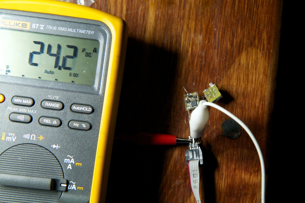
With these changes in place, I noticed a substantial decrease in power draw from my circuit.  While my previous sleep current was over 450

    \[\mu\]

A, my new current draw hovered around 25

    \[\mu\]

A.

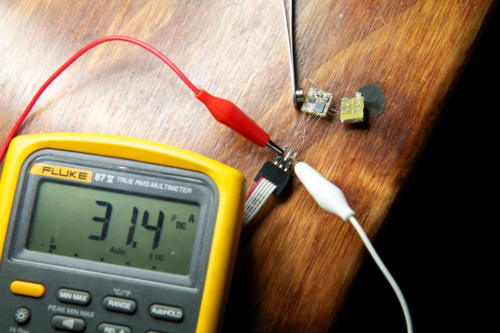
This went up slightly when a battery activated the hall-effect sensor, but still not much:

This is the state that the earrings will stay in when left in their box, and with such a small current draw, they will drain just 4% of the tiny 19mAh battery a day.  I’m curious to see if I can get it even smaller though as I may not really need the pull-up resistors at all since I’m using the two-FET solution.  I’ll have to play around with it later.

A moderately ruined Christmas

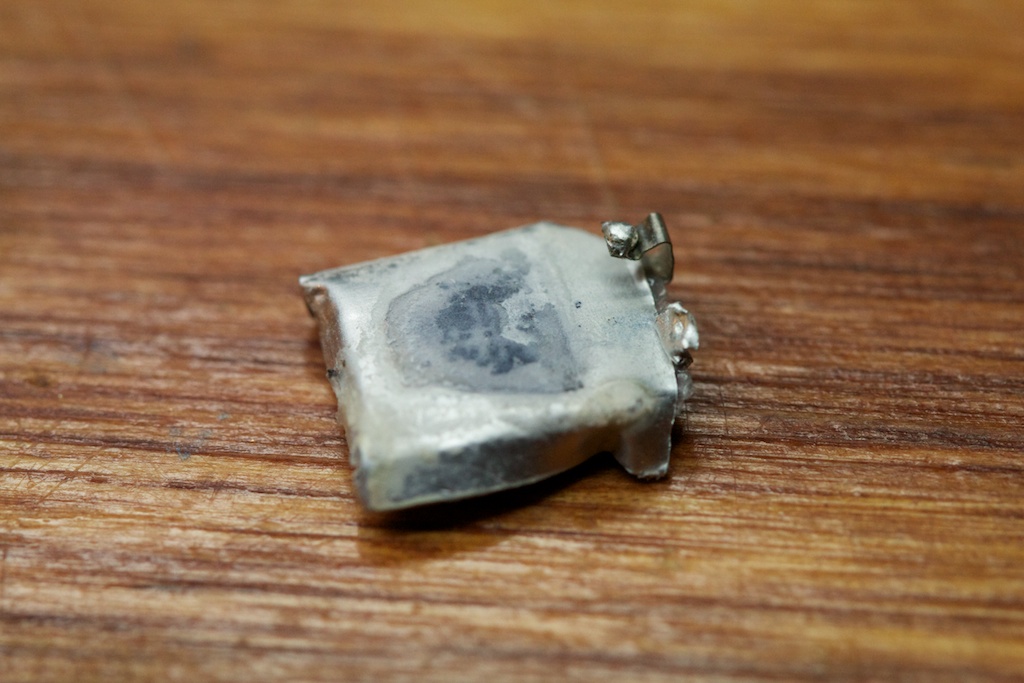
The circuits for these earrings have seen some serious shit.  By the time I was buttoning up the circuits for final delivery, I had wires breaking after being soldered and desoldered a dozen times.  Traces were starting to lift up off the PCB.  Solder-bridges everywhere.  Hell, one of my batteries even exploded in the process…

The short story is that they were ugly as sin, and I didn’t have enough time before the big holiday to fix them.

I explained to my sister that her gift may only be partially functional on Christmas day, and sure enough, the negative charging terminal on one of the earrings broke, so I was unable to charge it before giving it to her.

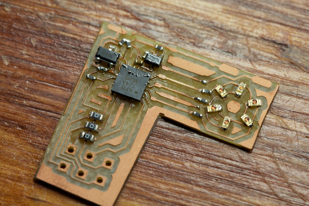
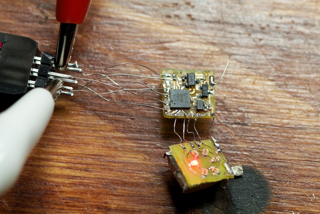
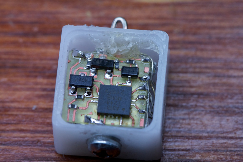
I took the earrings back and spent the last few weeks completely remaking their circuit boards until they looked like this:

I feel much better about giving them away in this state, and I’ll be mailing them out soon.

Conclusion

This turned into an insanely wordy post, and I really blazed through a lot of content here without much explanation.  I plan for the CNC machine to be a regular guest on the ch00ftech stage though, so expect a bunch of future posts with much more detail on how it works and what it can do.

In the mean time, I’m going to take a much-needed nap.


 Project files can be downloaded here.


4 thoughts on “CNC machine, Christmas gifts, and I’m a dope

  1. Pingback: Finally, party lights » Geko Geek

Leave a Reply to Steven Cancel reply

Your email address will not be published. Required fields are marked *