So today, I learned the importance of preventing things from bouncing.
The Problem
If you’ll recall with my windshield wiper project, I am using part of the windshield wiper motor to give me information on the wipers’ current location. Two of the five contacts that the motor provides connect to little metal brushes that run along a rotating metal disk. One of the brushes is in constant contact while the other passes over a small hole in the disk once per revolution.
The original purpose of this configuration is to allow the intermittent mode of wiper operation to work almost autonomously. The car will run current into one of these brushes and out the other to power the motor. When one brush reaches the hole, the motor will lose power and stop. This is what causes the wipers to stop at the end of a single wipe in intermittent mode.
Now, these brushes are designed for high current applications, not for precise position measurement. For example, if one of the brushes were to lose contact for 1ms or so, nobody would notice.
Recently, I’ve been trying to capture accurate information regarding how long it takes the wipers to complete a single cycle when setting them to various speed settings. I wrote a script that would try the wipers for one cycle at a speed setting, then change speed. My results look like this: (x axis is speed setting, y is time in seconds)
You get the general gist of what’s supposed to be going on by looking at the logarithmic slope you can see along the top. So what’s up with the rest of the data?
Well, I’m fairly certain that the brushes are “bouncing”. This is a common phenomenon with any kind of metal contact switch. When you smack two pieces of conducting material together, there is a very high probability that they will vibrate and have an intermittent connection for, say, a few hundred microseconds.
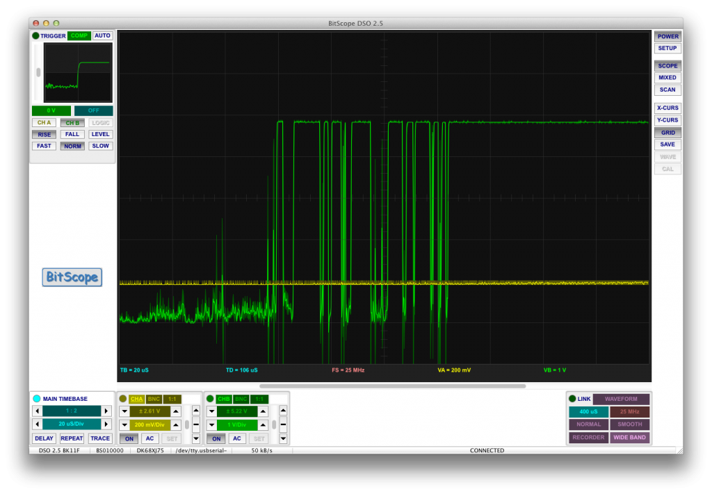
Here’s an example of one such vibration as the green signal passes from low to high (note the time scale is 20us per division):
This is an inconceivably small amount of time for a human, but it’s eons for a micro-controller. The micro might see a contact and separation happening a few microseconds apart and assume that the windshield wipers have made a full revolution in that time. It’s also possible that there are some bumps along my motor’s disk which is causing very brief disconnections in the middle of a cycle. I believe this is why there are so many quick measurements in the data I retrieved.
So, I needed to find a way to “de-bounce” my signal.
Solution
There are two potential solutions to this problem:
- Solve it in software
- Solve it in hardware
Software
De-bouncing is often solved in software by adding short delays after a correct reading. If you know the bouncing period is about 500us and the shortest time you should ever experience between switching on and off under normal use is on the order of 100ms, then you can have your code just ignore everything for 100ms after it receives a positive on or off.
This solution works very well with buttons (in fact, it’s probably what your keyboard is using right now), but it isn’t a perfect solution with my configuration because there’s a chance that the brushes will bounce at a random point in their cycle. Remember how they’re running along a disk? It’s possible that there are small bumps on this disk that could cause problems. By contrast, as a button is held down, nothing really changes.
Also, software is a pain. Hardware is where it’s at.
Hardware
What I really need here is a simple low pass filter. This will essentially smooth out my signal removing any extremely brief bumps.
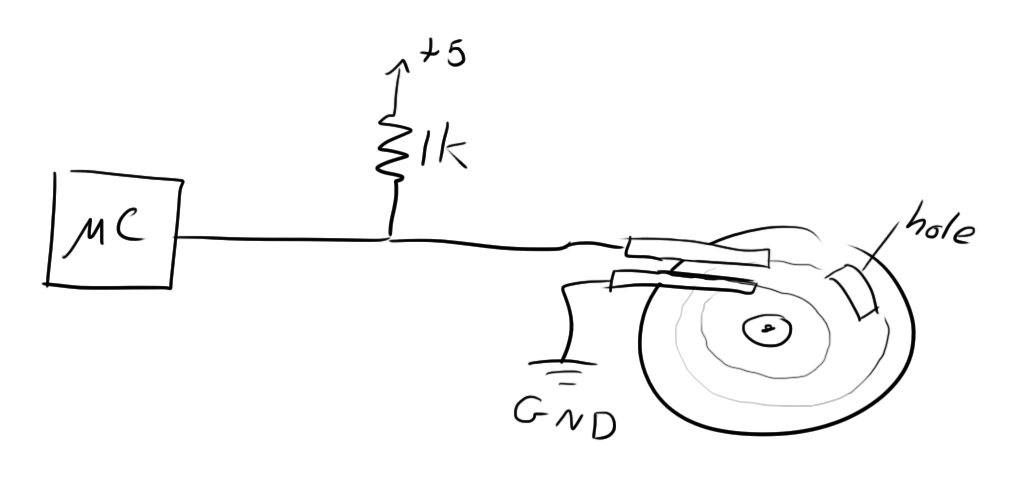
My original circuit looked something like this:
The idea is that as long as both brushes are touching the disk, the micro-controller input is grounded. As soon as the outer one goes over the hole, the input is pulled up to 5v by the 1k resistor.
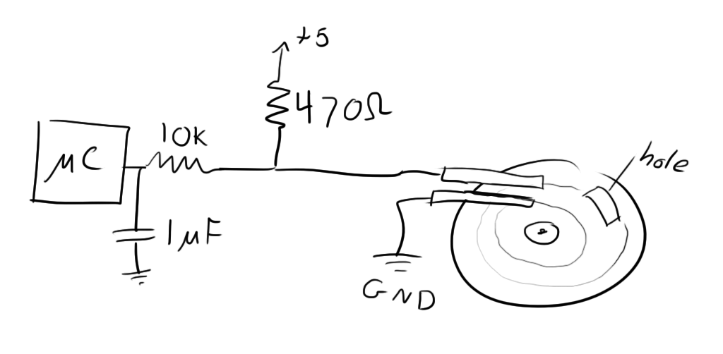
To implement a simple low pass filter, I added a resistor and capacitor as follows:
The 10k resistor and 1uF capacitor will have a time constant of (10,000*1E-6=) 10ms. This means that it will take about 50ms for the input to switch from high to low or low to high (about 5 time constants). I changed the 1k to a 470 because I wanted to make sure that the time constant was as close to equal for the pull up and pull down as possible. Keep in mind that for the pull up, you have to sum the 470 and 10k together when calculating the time constant. Ideally, I’d go as low as possible, but once you get down to the 100-200 ohm area, you start running into power dissipation issues because you’re dropping 5V across this resistor when the disk grounds the input.
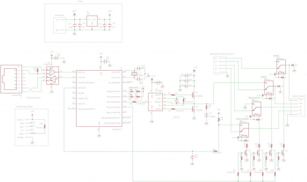
Luckily, these reworks were fairly easy to implement because of how my circuit was laid out. Here’s an updated schematic.
Results
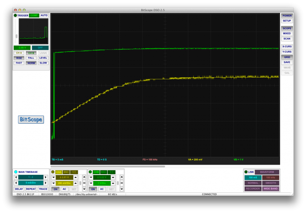
Though I haven’t had a chance to test it on my car, it definitely worked while testing indoors. Because I didn’t have the wiper motor to play with, I simulated the connections by touching a piece of wire to the ground plane or rubbing it along the ground plane. Here’s an example of the signal passing from low to high (disconnecting the wire from the ground plane):
The green signal is before the low pass filter and the yellow signal is after. As you can see, the green signal appears to bounce a little bit as it is lifted, but the yellow signal takes a while to rise. Here the time scale is 5ms per division, so the whole rise takes around 25-30ms. If this turns out to be too long, I can easily tweak it by swapping out the resistor for a smaller one.
And here’s a video demonstrating how well the fix worked:
I was being a little unfair towards the end of the first segment in how I was rubbing against the edge of the ground plane, but there are still a few incorrect messages towards the beginning where I’m rubbing on fairly smooth copper.
Anywho, the board is updated, and I’ll give it another go on the wipers as soon as I get a chance.
Continue this story here.


