After I posted the menorah yesterday where I said in passing that you’re not supposed to have circuit traces bend at right angles, I got a few questions from readers asking exactly why this is. The explanation is kind of complicated and involves some of Maxwell’s equations as well as multivariable calculus, but I’ll do my best to explain it in a way that doesn’t require any special knowledge of either of these topics. This is going to be a doozy, so read on if you dare.
Edit:
It has been pointed out to me that the information I present in this article is incorrect. While my explanation is theoretically correct, some sources have been presented to me that explain how the issues presented in this post don’t arise in practice. Here is one such source.
90 degree trace bends are still a bad idea for a number of other reasons, and this article is still an informative read if you would like to learn a little bit about basic EM theory.
Terminology
Flux
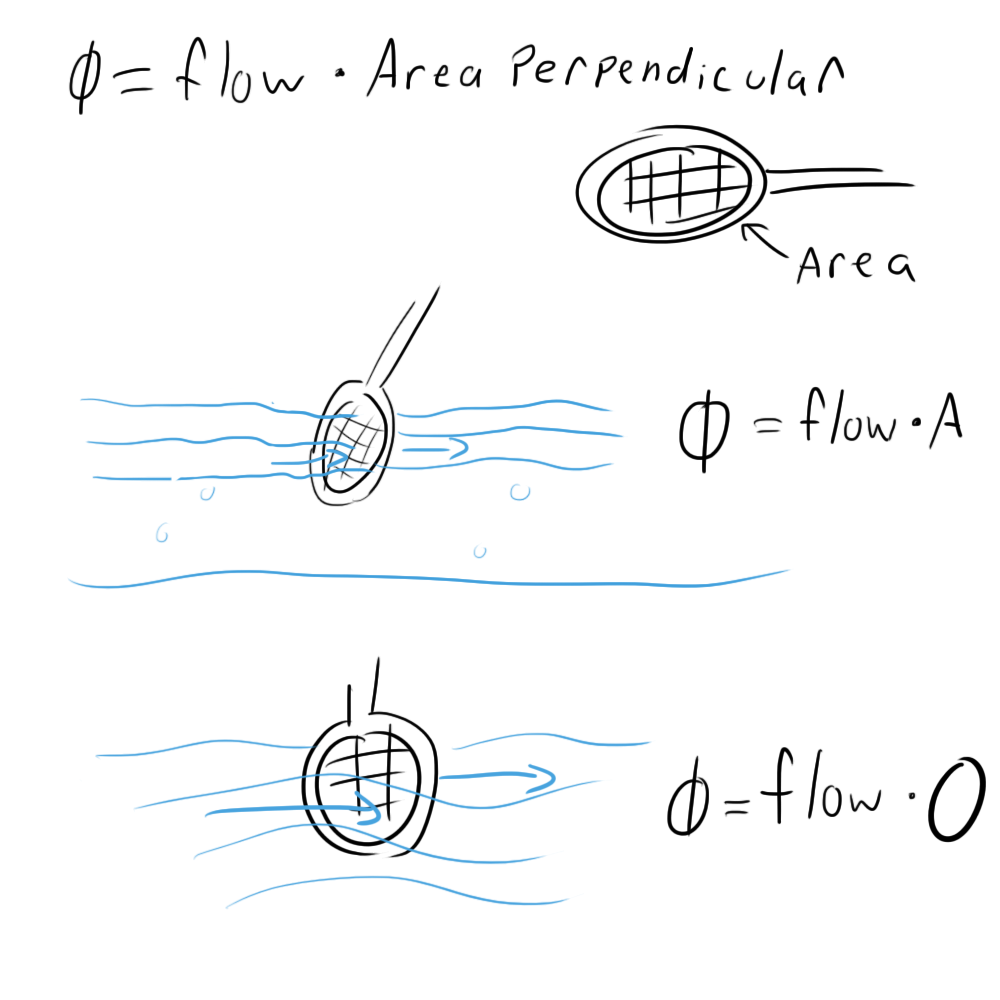
Flux (Φ) is a term that is used when dealing with vector fields. In this article’s context, it sort of describes the amount of electric field that is passing through a surface. Think of it this way: let’s say you have a river flowing by you and you dip a tennis racket into it. If you were to multiply the area of the tennis racket by the rate of water flow, that would be the flux of the water through the surface described by the rim of the racket. Increasing the size of the racket would increase the flux as would increasing the flow rate of the water.
If you were to turn the racket sideways so that the water runs along either side without passing through, the flux would be zero. Basically, flux is only concerned with the component of the water’s motion that is perpendicular to the area of the racket. If the water runs parallel to its surface, there is no flux.
Electric Field
Electric fields are vector fields that originate in positive charges and end in negative charges (we’re using conventional charge here by the way). A positively charged particle, when placed in an electric field, will feel a force in the direction of the field proportional the the strength of the field and the charge of the particle. If left to move freely, the charge will move in the direction of this force.
This is why electric fields must be zero inside conductors. If there was ever a non-zero electric field inside a conductor, the charges would be able to move along that field. Given enough time, all of the charges would find their final resting places and all of the electric fields would cancel out to zero. This all happens at roughly the speed of light, so it’s pretty safe to say that there is never an electric field inside a conductor.
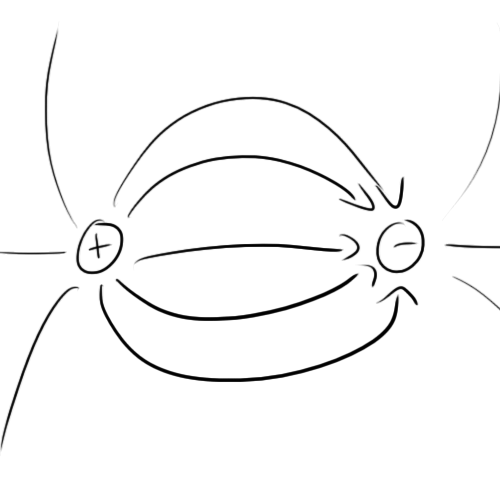
Electric fields are typically represented as curved lines with arrows pointing towards negative charges. The spacing between the lines represents field strength with closer lines representing stronger fields.
Electric fields can take on a number of shapes given the geometry of the charges. A single charge’s electric field might look like this:
When placed near a negative charge, it might look like this:
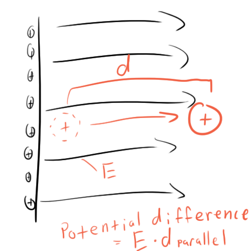
One configuration that is actually quite common (though it might not seem like it should be) is an infinitely large charged conducting plane. The following is a cross-section of such an arrangement. Notice that the charges line up on the surface. This is because they’re trying to get as far away from each other as possible (like charges repel).
Note that the fields are parallel to each other. This can only really be true in an infinite sheet. Think about it this way: if the plane goes on forever in every direction, what reason would the field lines have to arbitrarily go in any particular direction? That’s a pretty weak proof, but it’s easy, and it happens to lead you to the right conclusion.
In reality of course, there are no infinite planes of charge, but on a small enough scale, you can think of any plane as an infinite plane and get fairly accurate results.
Electric potential
Electric potential describes the energy that charges store when they are placed into an electric field. Remember what I said earlier about charges moving along an electric field? The movement of charge in such a manner is the conversion of potential energy to kinetic energy. Potential is usually thought of as a difference in potential between two points and is measured as the energy that would be released if a charge were allowed to travel between these two points:
Note that it is only concerned with the distance travelled parallel to the electric field. If you were standing on an infinite plane of charge and moved a free charge to the left a foot, you would not be changing its potential at all because its motion (left) was not in the direction of electric field (up).
An easy way to think of this is to draw “equipotential” lines which represent….well…points that are at equal potential. When we moved that hypothetical charge to the left a foot, we were moving it along an equipotential line.
If you want to measure the potential between two points, you just need to count how many equipotential lines you cross when going from point A to point B.
Measuring potential would be rather confusing if you had to constantly specify where your starting point was every time. Because of this, engineers typically use “ground” as a reference point. Although the ground potential in my wristwatch’s circuit is not the same as the ground point in your laptop, for all the components in a single circuit, the ground is the same.
So that’s enough for vocabulary. On to the nitty gritty.
Gauss’s Law
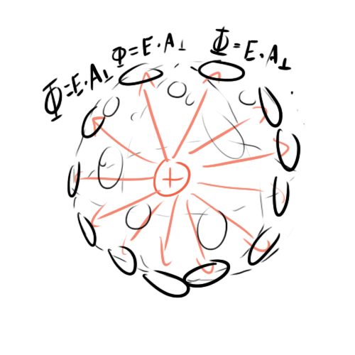
Gauss’s Law is one of Maxwell’s equations. It describes the relationship between the electric flux through the surfaces of a 3d shape and the charges contained within that shape. All you need to know is that the more flux you have, the more charge you have. Here’s an example:
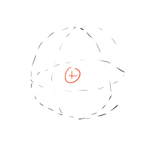
This is a single charge inside an imaginary sphere that we will consider our “Gaussian Surface”. To measure the flux, think of the surface of that sphere as being made up of tons of tiny little tennis rackets from our metaphor, then measure the electric field passing through each of them.
Note that A-perpendicular is just A in this case because the geometry dictates that the electric field lines will always be perpendicular to the sphere’s surface. This is why we don’t use a cube in this example.
The sum of all of these little fluxes will equal the total flux generated by this charge and will be proportional to the charge.
You might be wondering how this can be. What prevents us from changing the size of the sphere without altering the charge at all. After all, it’s an imaginary sphere, we can do whatever we want to it without touching the charge. Wouldn’t changing the Gaussian surface change the flux?
The answer is: No.
Notice that the electric field lines spread out as they get farther away from the charge. As I said before, the density of the electric field lines represents the field’s strength. As it turns out, the farther away you get from a charge, the weaker the electric field.
So, let’s say you use tennis rackets of the same size to make a larger Gaussian surface. You would probably need a lot more tennis rackets. Each of these rackets would have a weaker electric field passing through it, and after adding them all together, you would end up with exactly the same amount of total electric flux and therefore the same amount of charge.
Gauss’s Law on an Infinite Conducting Plane
Let’s return to our concept of an infinite conducting plane. Does Gauss’s law work here? Yes!
Here is a drawing of a Gaussian cube measuring the charge on the surface of an infinite plane:
That’s a little confusing to deal with, so let’s drop down to a two-dimensional cross section. Once you understand it in 2d, it should be pretty easy to jump back to 3d.
Applying Gauss’s law is quite easy. All of the cube’s surface that exists inside the conductor can be ignored because the electric field inside a conductor is zero. Likewise, all of the sides of the cube can be ignored because their tennis rackets run parallel to the electric field. That means that the area of the top of the cube is proportional to the charge inside it.
This makes sense when you think about it. The only way to increase the flux is to increase the area of the top. Making the cube taller or shorter will have no bearing on the flux. The perpendicular area and electric field strength are unchanged.
So how does this all relate to bent traces?
On a small enough scale, you can think of a trace in your circuit as its own little infinite plane (it’s a stretch, I know, but it works, trust me).
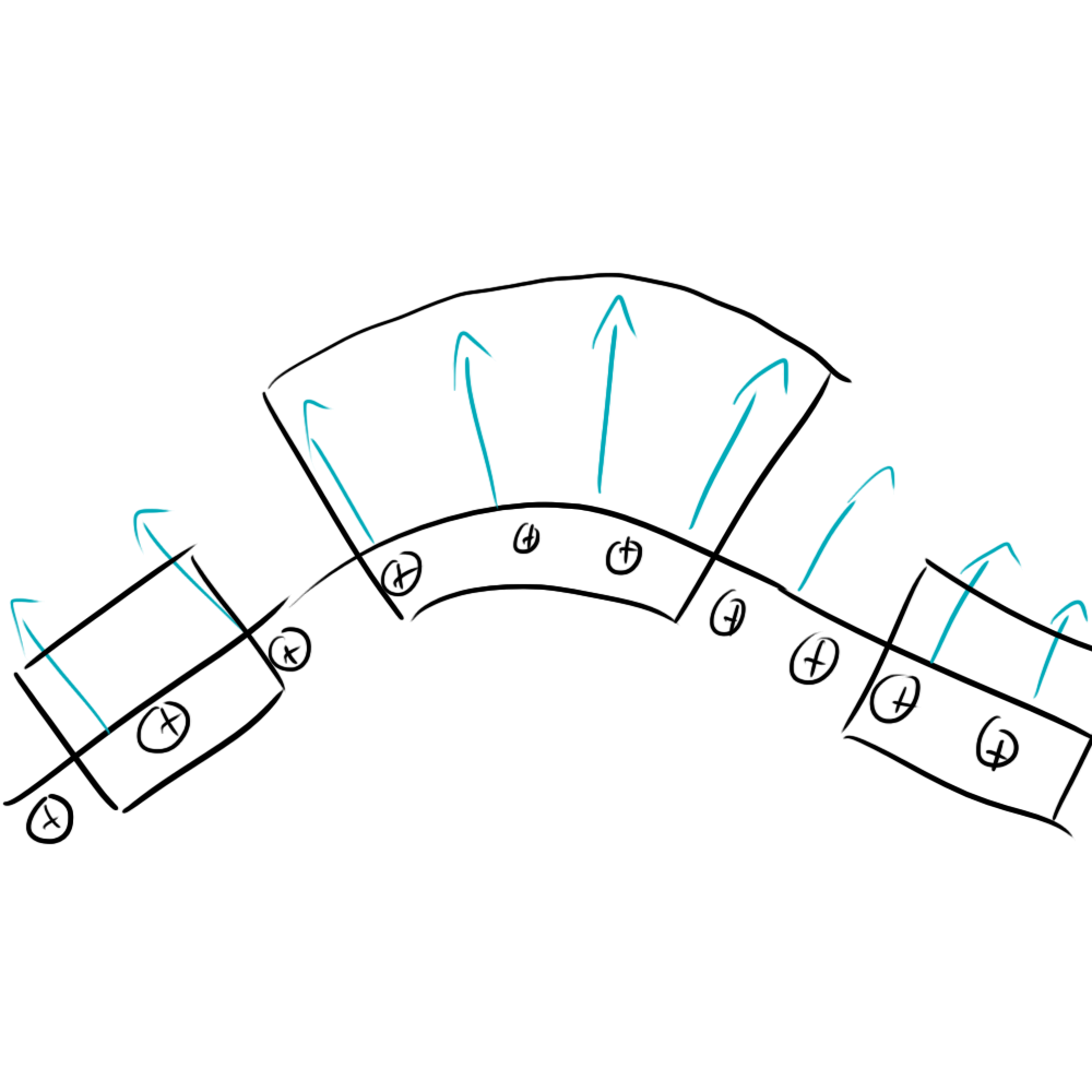
Let’s try applying this Gauss’s law technique to a slightly bent infinite plane:
For the Gaussian shapes on the right and left, nothing has changed, but for the one in the middle, a lot has. Remember how we could make the cube as tall or short as we wanted before without changing anything? With the geometry of the bent edge, making it taller will increase the area of the top surface. Because the charge inside the surface isn’t changing, this means that the electric field must be getting weaker so that the flux remains the same.
This is kind of like our sphere problem from before. More tennis rackets means weaker electric field. You could also have figured this out by just looking at how the electric field lines in the drawing get farther apart as you move away from the plane, but who wants to trust a doodle?
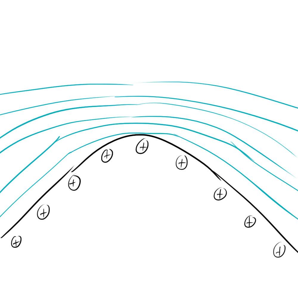
So what’s the big deal? Why can’t you let your electric fields get weaker? The real issue is not them getting weaker, but them getting stronger. With the case of the infinite plane, you could get infinitely close to the conducting plane without altering the electric field at all. Now, as you get closer, your relevant Gaussian surface shrinks in size. Because the surface is shrinking, the electric field must be growing the compensate. Take a look at what this does to your equipotential lines.
As you can see, the equipotential lines are packed closer together because the electric field strength is higher, closer to the plane.
Now eventually, with this configuration, you’ll reach some kind of maximum potential when your Gaussian surface crashes into the surface of your conducting plane. What about in the case of an infinitely pointy plane?
No matter how close you zoom in, you can still draw the same gaussian surface that encompasses the same charge. That means that as your tennis racket gets infinitely small, your electric fields must be getting infinitely large! Of course, this doesn’t happen in real life, but it gives you an idea of the trend you can observe when your conductor gets pointier and pointier.
Okay, so we’ve got a lot of equipotential lines crammed together and a lot of electric field. Who cares?
If you have a sharply pointed charged conductor, you will have a strong electric field around that conductor. So smooth it out a bit. 45 degrees is as sharp as you should get.
Basically, when you boil it down, having a pointy trace will increase the likelihood of your circuit acting strangely. For example, high frequency signals passing over these traces will generate large, rapidly fluctuating electric fields which could cause your circuit to give off some unwanted EM radiation.
Also, pointy traces can also be prime targets for electrostatic discharge as the large electric field will suck charges out of charged bodies that get near them. In fact, a lot of circuit builders will often intentionally place a pointy ground trace and a pointy signal trace very close to each other to draw any ESD on that signal trace (say, if it goes to an external port that the user might touch) safely to ground and away from any sensitive components.
In fact, a lot of people have been using this technique on a larger scale. Lightning rods are usually made to be very pointy so that will literally suck charge out of the sky and direct it safely to the ground out of the way of any sensitive structures or people.
Conclusion
I hope that sums it up for you. I actually had to do a little review from an old textbook to write all of this, so it was definitely a worthwhile refresher. I hope you enjoyed reading it as much as I enjoyed writing!







That was awesOme
You made it EASY to understand
You should consider a book or TV/webcast explaining EE
Very nice. As a physics student, Maxwell’s equations are well known to me, but it’s nice to know about their practical consequences as well. You explain things very clearly.
The old 90-degree-angles-are-bad myth.
Read this:
http://www.sigcon.com/Pubs/edn/bigbadbend.htm
It’s from Howard Johnson. If there is an expert on signal integrity, it’s him.
He was a guest von the “Amp Hour” podcast some time ago:
http://www.theamphour.com/2012/01/10/the-amp-hour-77-winsome-waveform-wizardry/
You present the general consensus that I got from a number of commenters and it seems that you’re right. Either way, there are a number of reasons why 90 degree traces are a bad idea, and since my post outlines a few tenets of EM physics, I’m going to leave it up.