Were you expecting an armoire?
Background and motivation
One of the best parts about living on the west coast is that you always wake up to interesting news from your family back east who have already been up and about for a few hours. Back in August, I opened my eyes to an email from my Aunt to the entire family:
Subject: Very sad day for this federal government worker…
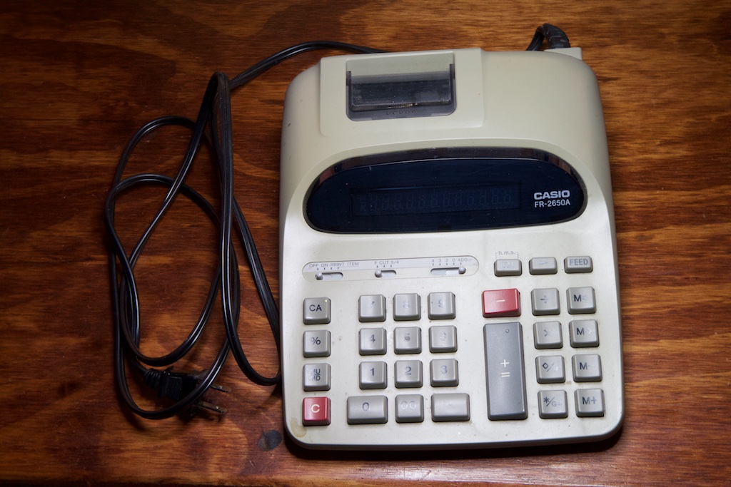
After 42 years working in the federal government my electric calculator died. Why is this so sad for me… because the calculator I have used my entire government career is actually the same one my dad used. When dad retired he gave his calculator to me. So god only knows how old the thing really was. The paper feeder stopped working years ago, but now you can’t see the numbers anymore. They became fainter and fainter. I babied it as long as I could.
So today I went and took the calculator out of my retired bosses office to use. So I will continue my government service using another retirees calculator. Its not the same as using dad’s, but at least the tradition of using a retiree’s calculator continues (until I retire and leave it to someone else).
Just thought you all would enjoy my story about me and my dad!
Love, Saundra
In my half-asleep state, I grabbed my phone and fired off a rather confident and dramatic text:

I didn’t know exactly what was wrong with the calculator, but I figured I’d at least get a decent blog post out of it and at best end up with a great Christmas gift for my aunt!
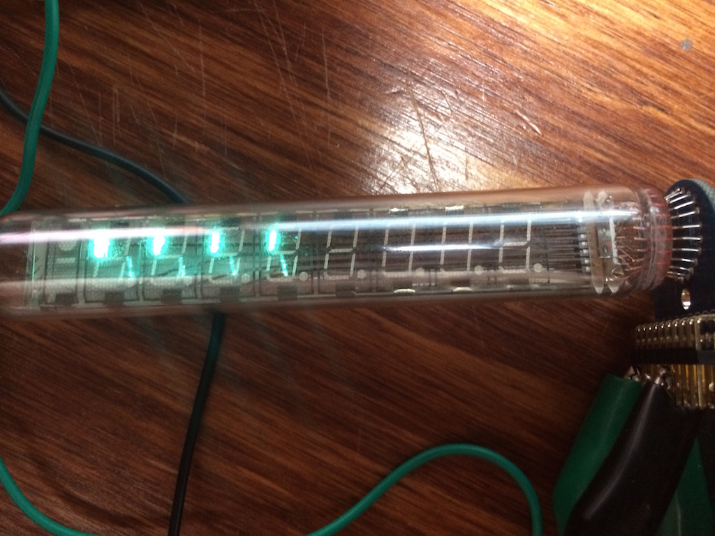
I wasn’t going into this blind however. Knowing the age of the calculator, I figured that it used vacuum fluorescent display technology. Though I haven’t built anything with VFDs, I did purchase one to play with a few months ago and managed to get it to at least light up:
So over Thanksgiving, I nabbed the patient and got to work.
VFDs
Up until LEDs got cheap and bright enough, vacuum fluorescent displays were the state of the art. VFDs are evacuated tubes that manipulate electrons with electric fields in order to illuminate an anode coated with a phosphorescent material.
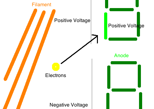
The basic principle goes like this:
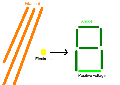
A thin filament or grid of specially coated wires in front of the display is heated. Due to “thermionic emission,” when these wires are heated, they emit electrons into the vacuum. Electrons are attracted to positive potentials, so a positive potential is connected to various anode segments of a seven segment digit in order to attract them. When they eventually strike the anode, they react with its phosphorescent coating and emit light.
A practical problem arises when you have a multiple digit display though. If each segment of each digit requires its own electrical connection, you end up needing a lot of pins. My Aunt’s calculator supports 12 digits which would require 84 pins to drive not counting those pins required for decimal points or other symbols.
To reduce the number of connections, a separate anode grate is placed in front of each digit. When the anode is given a positive voltage with respect to the filament, it attracts electrons towards that digit. When it’s given a negative voltage, it repels them. This allows the designer to light up a single digit at a time. By lighting each of them up quickly in rapid succession, you can give the appearance of having all lit up at the same time.
As such, all 12 digits can have their segments wired up in parallel greatly reducing the number of pins required. A 12 digit calculator now only needs 7-9 pins (one for each segment, decimal, and whatever other bits) plus an additional pin for each digit.
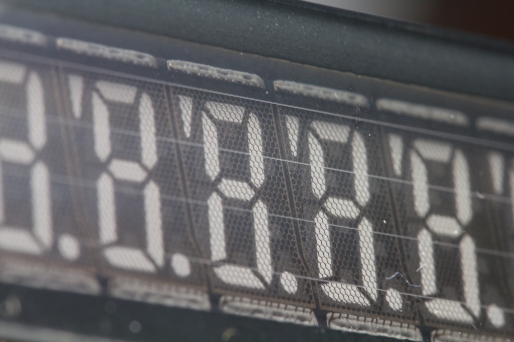
This is pretty obvious when you look at the display up close:
Knowing what I knew about VFDs, I set to work with the patient.
Disassembly and diagnosis
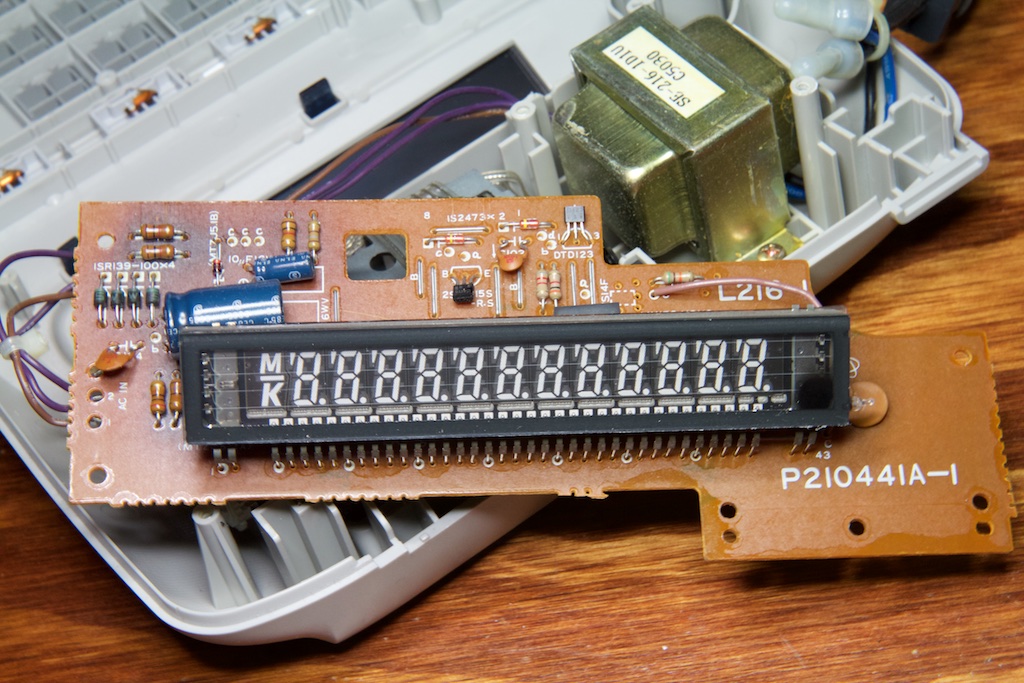
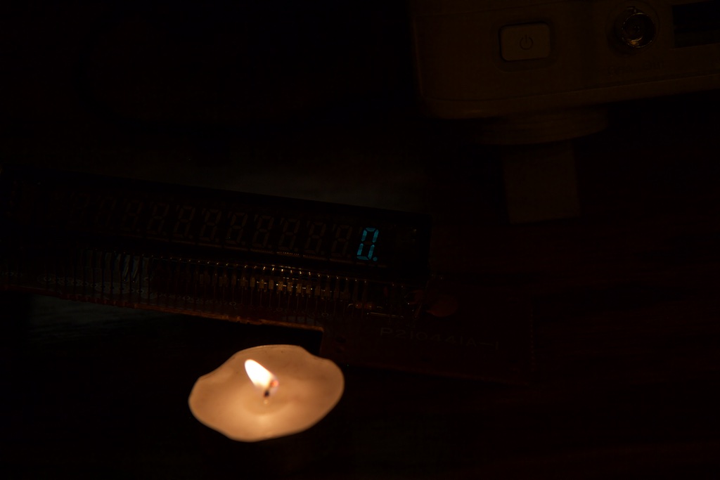
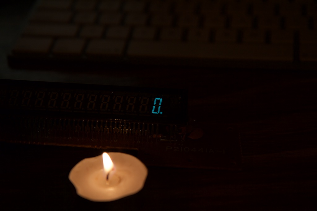
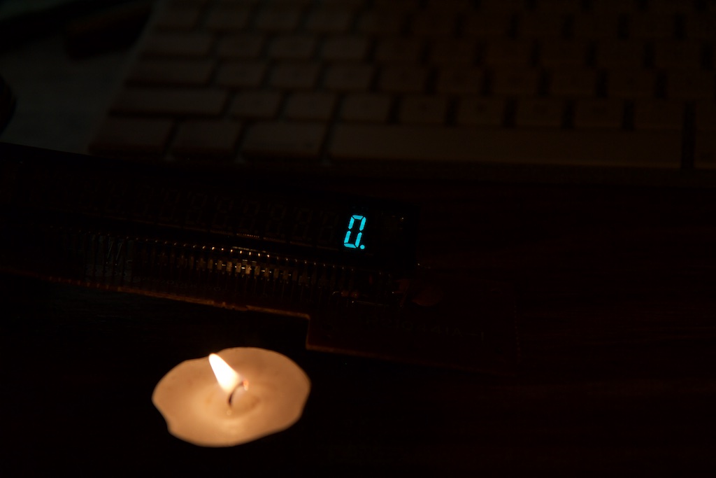
The calculator was in a pretty sorry state. While it was still mostly functional, the display was indeed so dark that it could hardly be read:
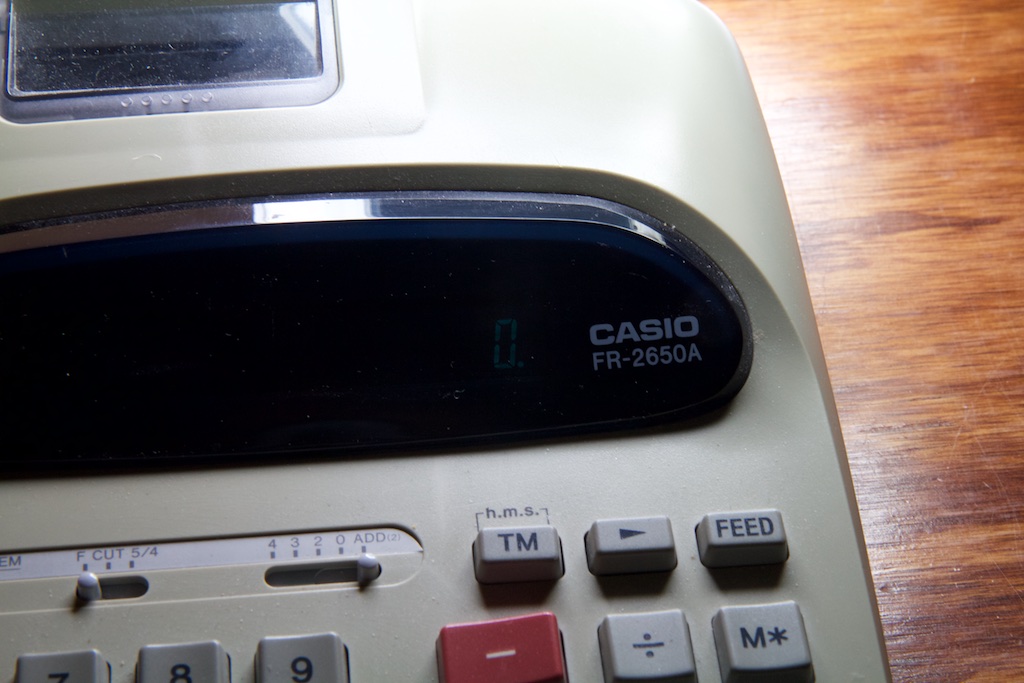
It’s hard to believe, but this thing is in fact turned on. In addition to being super dim, it also flickered quite a bit during operation.
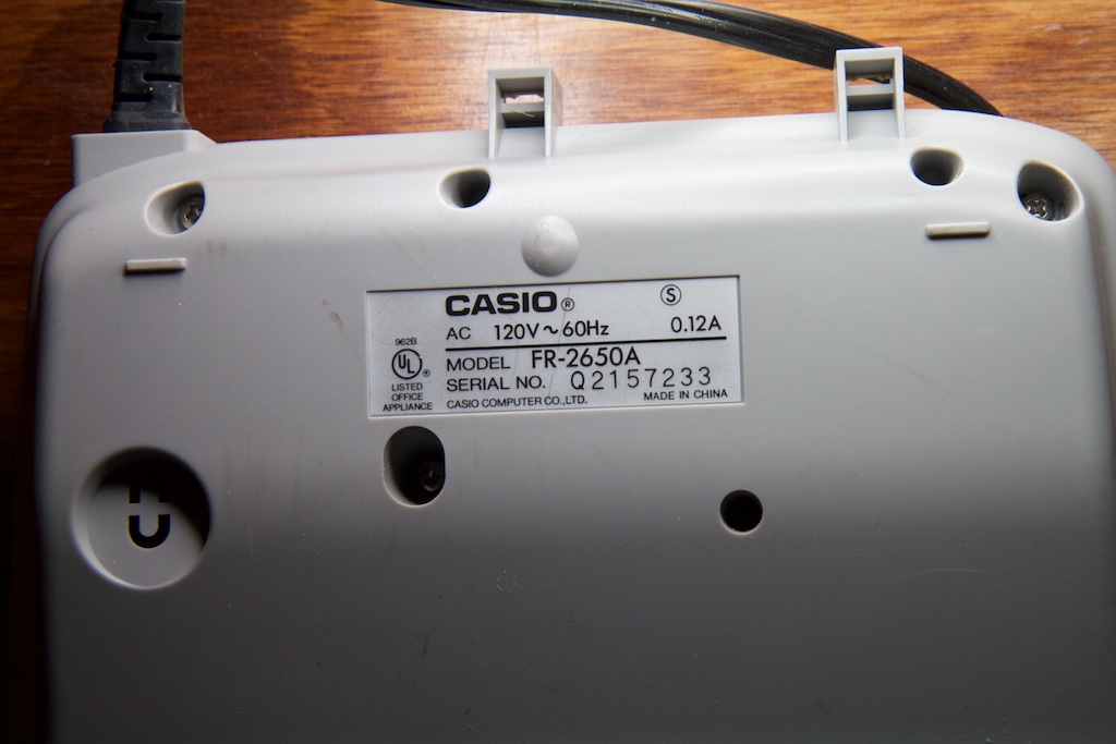
Step one was taking it apart. After removing a few screws on the bottom, the thing came apart pretty easily.
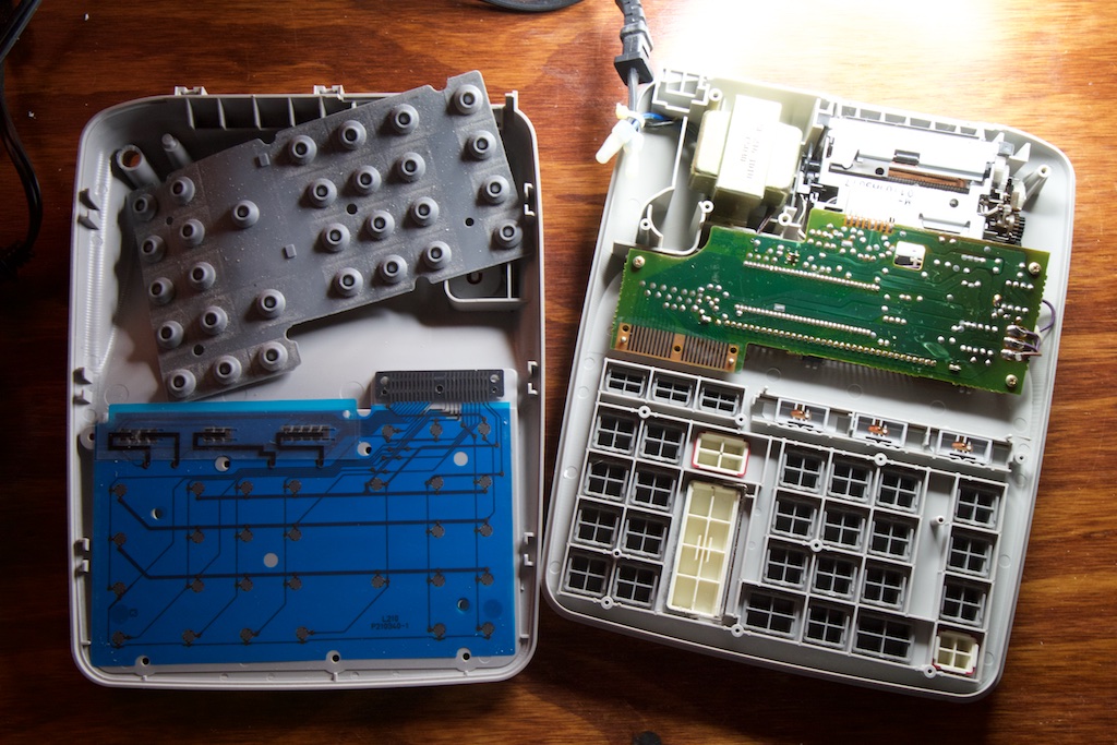
The keypad had a familiar construction of conductive rubber pills on the bottom of a rubber sheet that interfaced with conductive traces on the blue plastic sheet. When the user presses one of the plastic buttons, it presses down on the rubber sheet and shorts the two traces together. One thing I haven’t seen before was using a similar technique for the three slide switches.
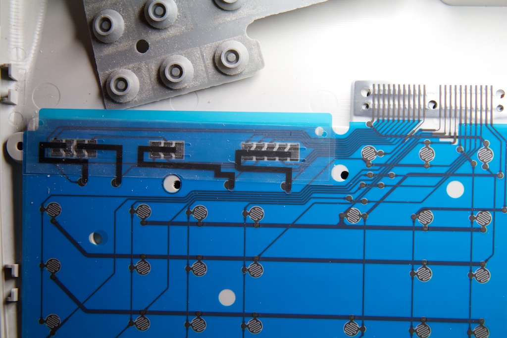
Though the switches never make electrical contact with the traces on the plastic sheet, they provide pressure to push two conductors together, so each switch location acts like a separate button.
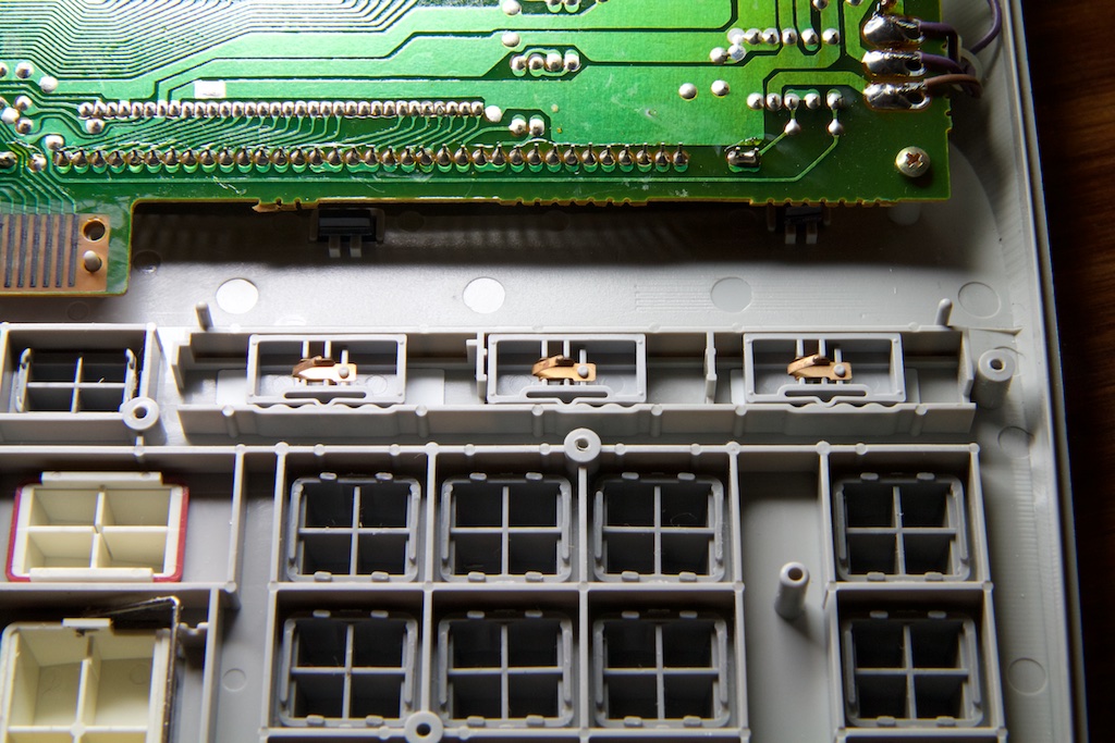
The other half of the device contained the display, power transformer, and main circuit board.
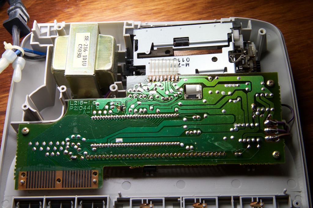
The entire calculator is driven by a single IC which I have to believe was custom built for exactly this application seeing how it manages all of the math as well as the keyboard, display, and printer.
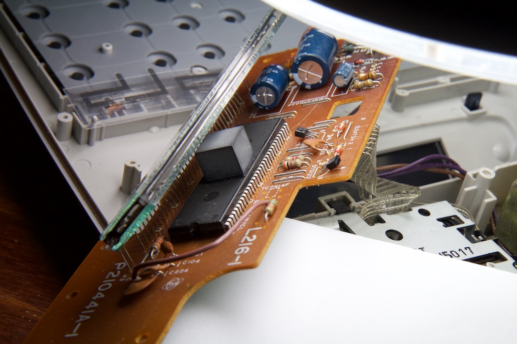
That’s a huge chip!
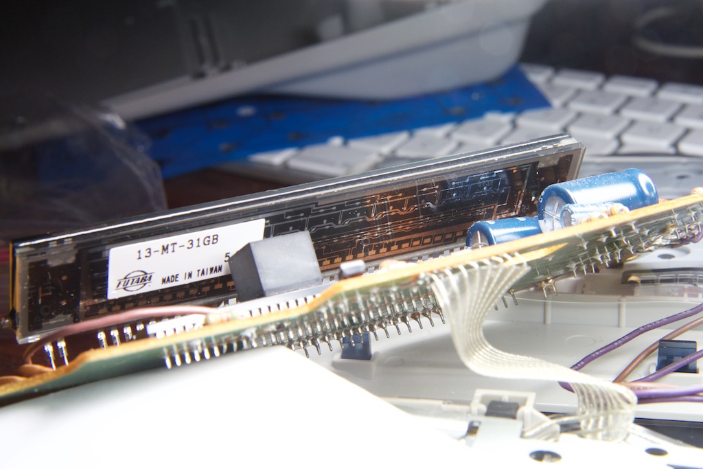
The display is made out of clear glass with some metal bits making up the traces and symbols. Some of the circuit is visible through its transparent back. If you look closely, you can see what I was talking about with each digit being wired together in parallel:
I was a little concerned about a black blemish I noticed to the bottom right of the display:
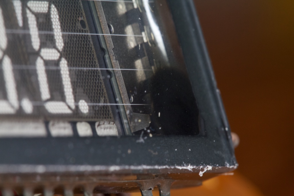
I’ve heard that VFDs “wear out” over time, and I wondered if this had something to do with it.
Update:
Reddit user madscientistEE pointed out to me that this blemish is actually a “getter flash” which consists of a chemical used to absorb any stray gasses that may have seeped into the tube. The fact that it’s still black is actually a sign of health.
Caps
With the calculator apart, I immediately started poking around. I found a few large electrolytic caps which I thought were a good place to start:
The largest cap was 2200
![\[\mu\]](https://ch00ftech.com/wp-content/ql-cache/quicklatex.com-bee17ce5c29d6fa9fa02b47a477d5c06_l3.png "Rendered by QuickLaTeX.com")
F and was sitting at a potential of about 7.5V.
The next cap was 220
F at 22V. I remembered reading that VFDs typically operate at 30V or so, so I figured that this warranted some more investigation.
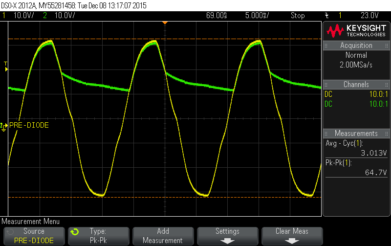
I captured this scope trace across the cap:
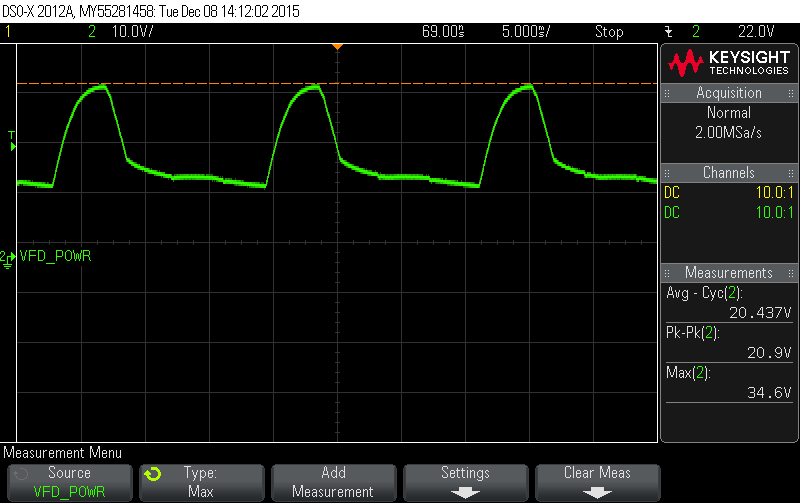
21V peak to peak?! That’s quite a bit of swing! I had good reason to believe that this supply was supposed to be used to drive the VFD especially after I tried probing one of the lines going to the display at the same time:
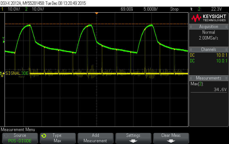
This could help explain the flickering I was seeing. The “SIGNAL” trace is switching digits on and off in sequence, but because the frequency is not the same as the ripple in the voltage rail, the same digit may fire up at a lower voltage some times and appear dimmer. This would happen at the “beat frequency” of the 60Hz ripple and whatever the refresh rate of the calculator is. Though these two frequencies are faster than what can be seen by the naked eye, the beat frequency is lower and is visible.
So how is this wiggly voltage rail made anyway?
Inspecting the PCB was pretty easy considering it was just a single layer. As far as I could tell, the schematic for this rail looked something like this:
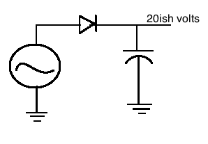
Pretty straight forward, right? One of the phases of the transformer was used to generate a high voltage sine wave which was then rectified into a DC rail. Due to the fairly small current draw of the VFD, a full-bridge rectifier wasn’t necessary.
Taking a scope trace on the non-capacitor side of that diode gave me this:
So it looks like the voltage on the output more or less tracks the input, but that capacitor wasn’t doing a good job of keeping the rail steady.
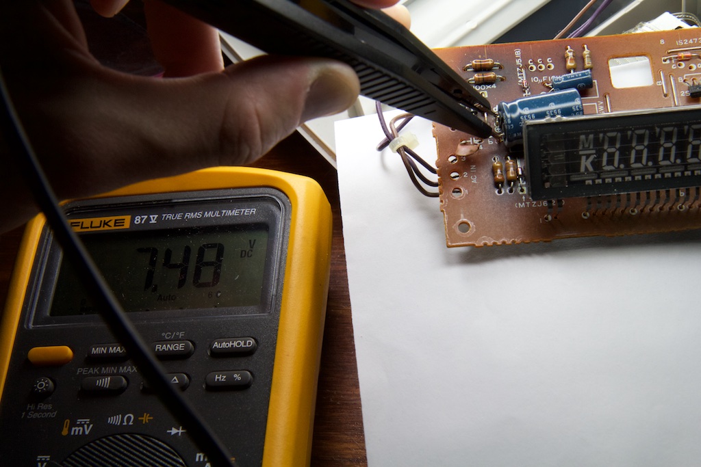
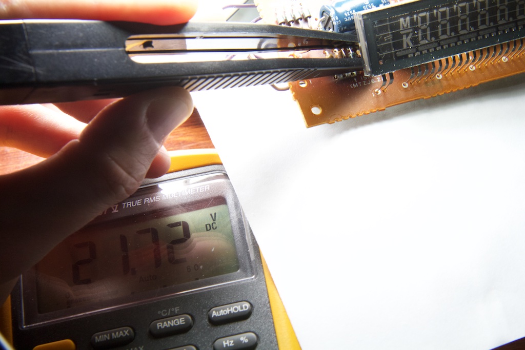
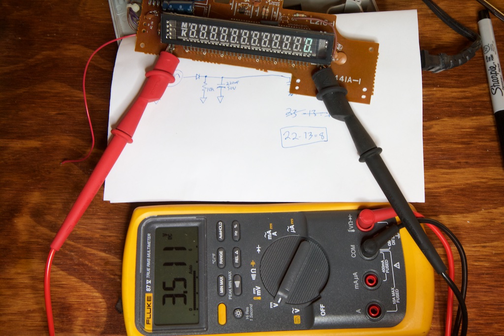
Although I’ve never seen one in person, I’ve heard that old electrolytic capacitors can “dry up” and lose capacitance over time. With this in mind, I removed the relevant cap and took a poke at it with my multimeter:
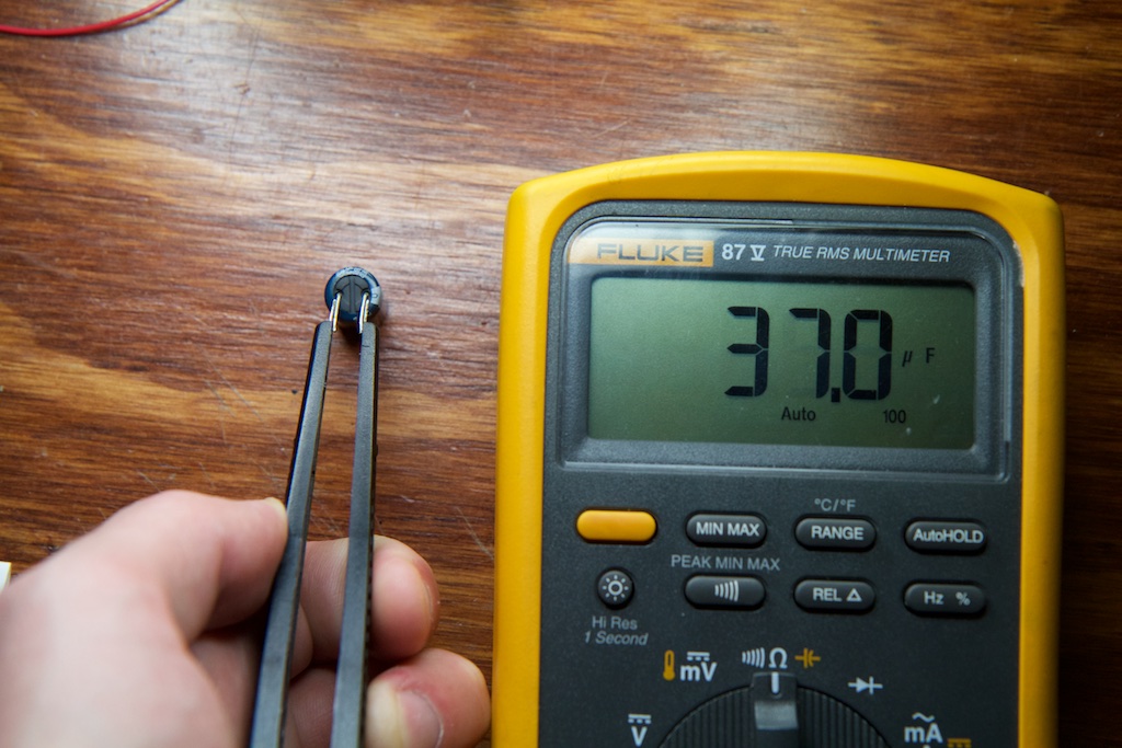
Yowza! 220
F had dropped to 37
F! I guess forty-some years will do that to a cap. I’m not sure how the performance of a cap changes as it dries up, but I wonder if I’d see an even bigger drop at a larger DC bias given how above a certain voltage, the waveform tracked the diode exactly.
On to find a replacement. Fortunately, electrolytic caps haven’t changed much in the past half-century, so it was just a matter of typing in the specs on Digikey:
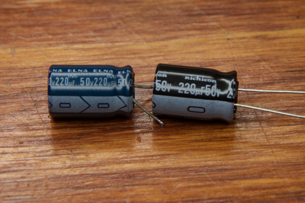
Couldn’t find it in blue…
With the new cap installed, the voltage rail instantly looked a lot better:
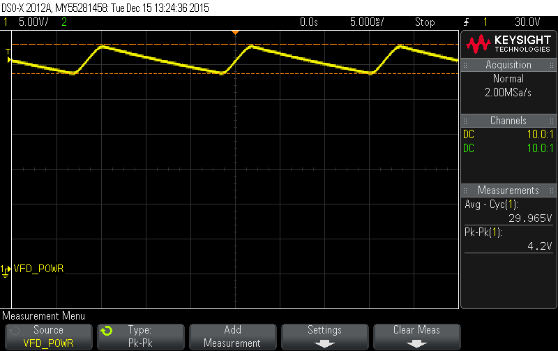
And indeed, the brightness of the display improved. Before:
And After:
And no more flickering to boot!
Just to be safe, I replaced the other two electrolytics as well. The 2200
F had dropped all the way to 1000
F!
Filaments
Phosphorescent materials (like those used in EL wire) emit light through chemical process, and these chemicals tend to lose their potency over time. As such, even with a perfect power supply, the display wasn’t as bright as it might have once been. In order to get its brightness back, I had to overdrive it a bit.
The filament is responsible for providing the electrons to the display. By increasing the power going to the filament, I hoped to increase the number of free electrons hitting the anodes and increase the brightness.
The filament is basically a giant resistor that is placed in series with two other resistors and powered off the 7.5V supply:
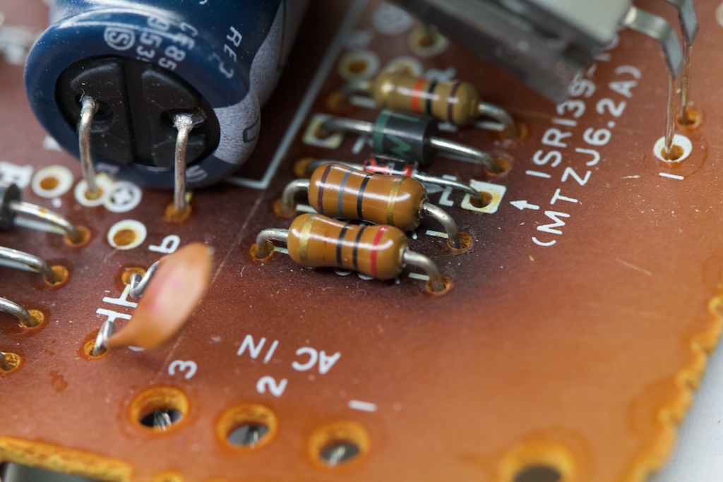
I’m not entirely sure why they chose to put a resistor on either end, but there was a 20
![\[\Omega\]](https://ch00ftech.com/wp-content/ql-cache/quicklatex.com-5060d7d946cd178c2e892e089190f3ff_l3.png "Rendered by QuickLaTeX.com")
resistor to the 7.5V supply side of the filament and a 17
resistor between it and ground. I suspect this made the filament more “neutral” which helped with directing the electrons around. When operating, the filament saw about 3.5V:
Which works out to about 94mA of current.
In order to increase the heat on the filament I opted to simply short out the 20
resistor. The results were very noticeable. Before (same as above):
After:
I don’t know what would have happened had I shorted out the low-side resistor instead. I was in a bit of a hurry at the time, so I didn’t perform too many experiments. I suspect that shorting the low-side resistor may have made it more difficult for the cathode grate to block lower potential electrons from hitting their 7-segment anodes, but that’s just a guess.
So a few adjustments, and the display was as good as new! I still had a few days left before the holidays though so I thought I’d take a stab at the printer.
Printer
The larger 2200
F capacitor was connected to some traces going to the printer module, so I wasn’t too surprised to find it functional once I reassembled the calculator. This calculator print head doesn’t work like a thermal printer. Instead, it has numbers and symbols printed on wheels which rotate and push ink onto a roll of paper like a typewriter. I’m not entirely certain if replacing the cap fixed the print head (I didn’t test it before), but it was definitely trying to print after.
The only problem was feeding paper. Trying to shove a roll of paper into the back of the printer while hitting the feed button didn’t do much. The paper only went in about a quarter inch, and often came out with what looked like a small bar of black ink soaked into it. I figured that maybe ink had gunked up the paper feeder over the years and needed to be cleaned out.
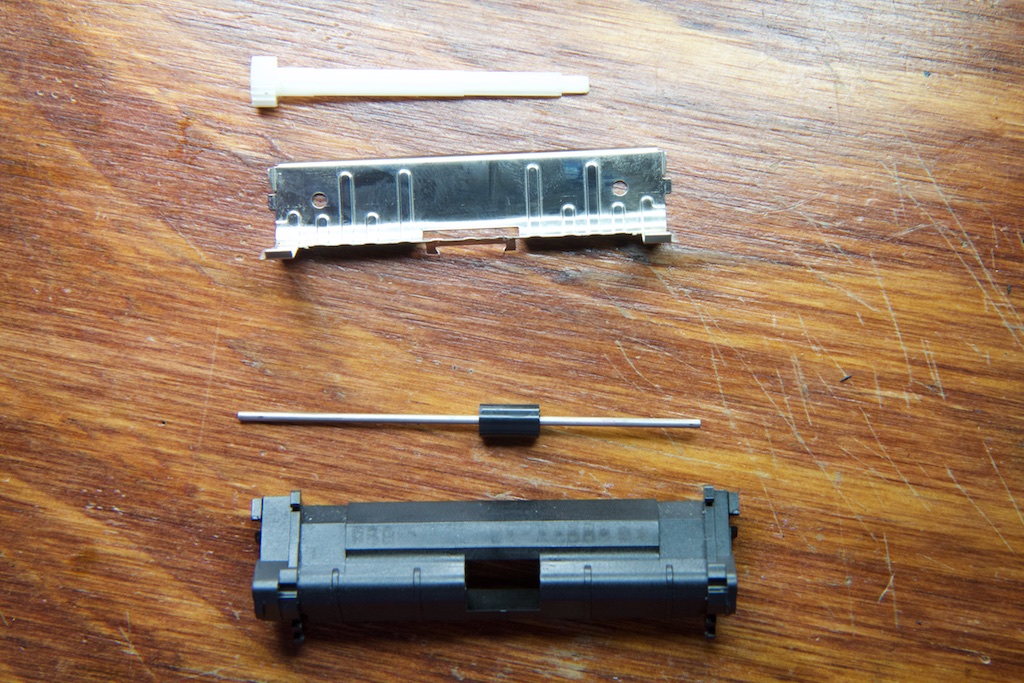
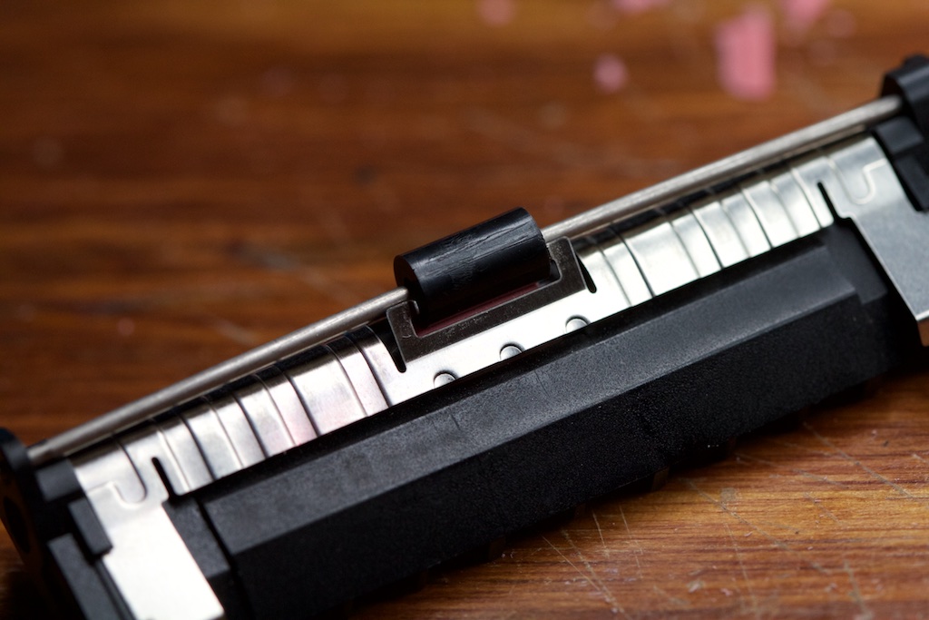
Taking the print-head apart, I found a two roller system with a soft-rubber roller driven by the motor and a hard plastic roller that was pushed up against it. It looked like the soft-rubber roller was stuck, so I tried to force it free with a pair of tweezers. The results weren’t great:
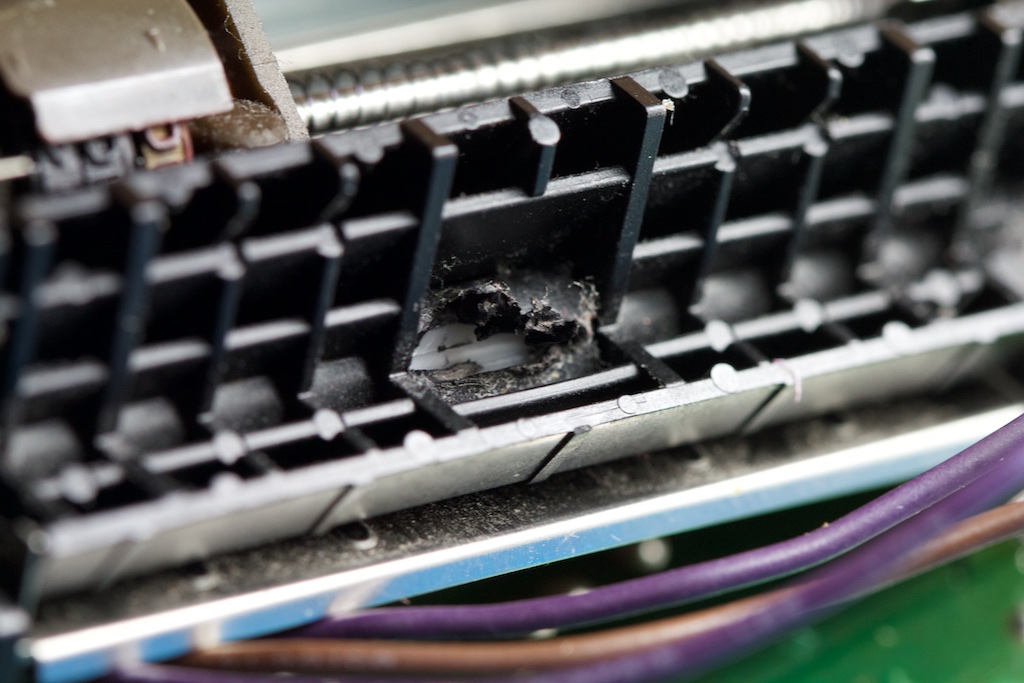
It may not be super obvious from this picture, but the roller was so old that the rubber had decayed into some kind of black goopy mush that instantly fell apart as soon as any pressure was applied to it. That black bar on the paper wasn’t ink, it was roller residue. What you see above was accomplished with some gentle prodding with a pair of tweezers. It looks like the spindle was still turning, but the roller had fused to the sides of the housing.
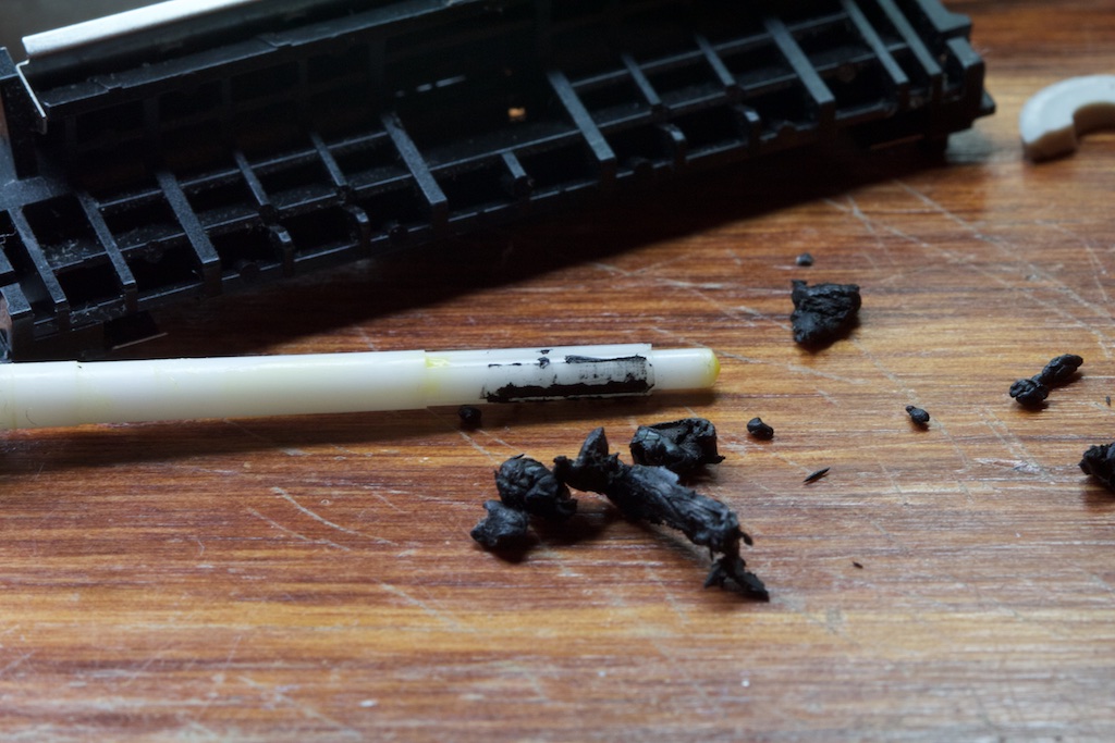
Obviously this roller had to go. I quickly set to work disassembling the printer (which mostly snapped together) and cleaning out all of the bits of black goopy residue:
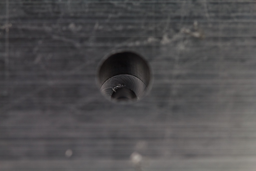
All I needed now was a roller. The spindle had some “teeth” on it for gripping the inside of the roller, so I figured I could try casting a new rubber roller around the spindle and all would be well. Step one was making a mold. Obviously the old roller was gone, so I made some approximations on what its dimensions might have once been and used my CNC mill to carve a hole into a piece of Delrin:
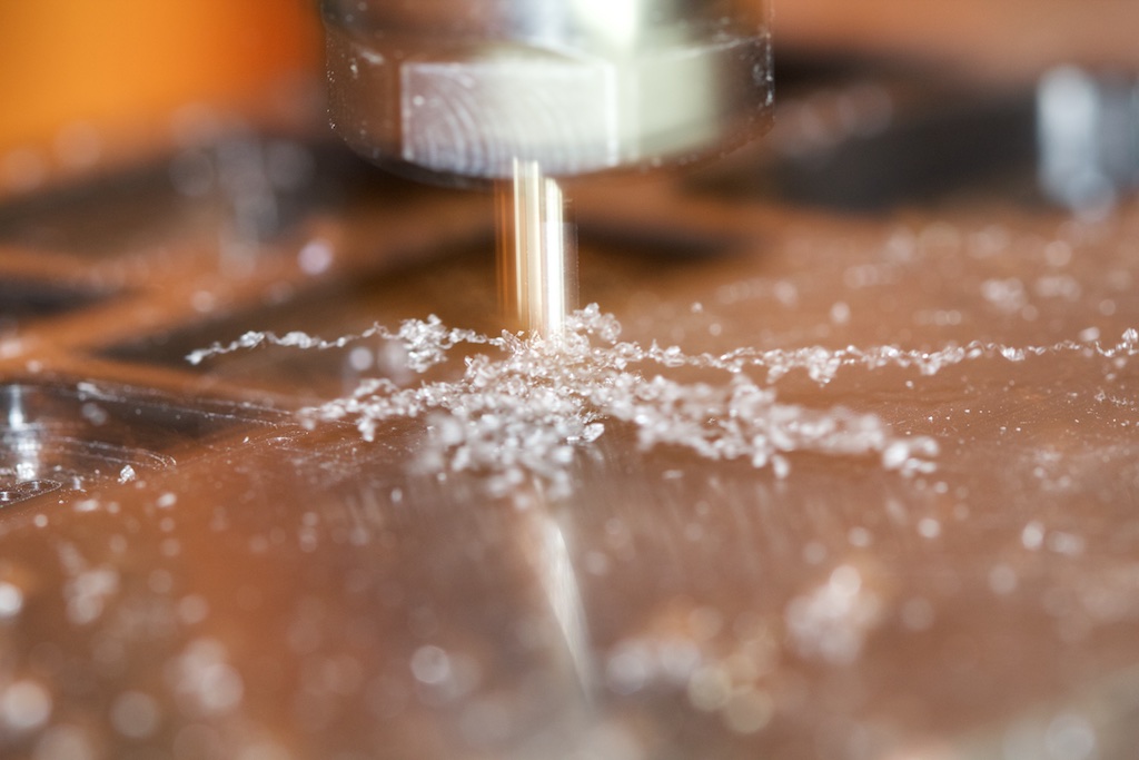
I added a smaller deeper hole in the middle for the part of the spindle that extends beyond the roller. My thought was to cast the rubber roller like you might make a popsicle in the freezer:
Next up was making a small mixture of some two-part silicone rubber:
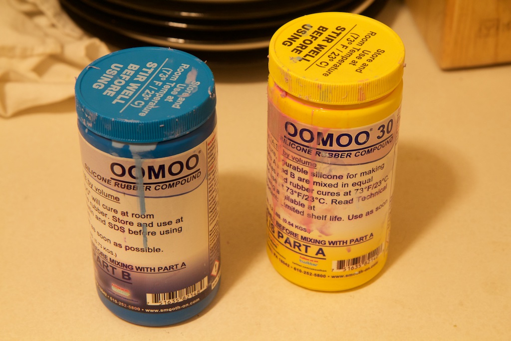
Equal parts pink and blue gives you a purple goo that solidifies in a few minutes. I’ve used it before for making molds for some electronics enclosures. Sadly, I haven’t used this stuff in probably over a year, and the pink goop had totally solidified in the jar.
Bummer.
With no time to order a replacement, I looked around my apartment for anything else I could use to replace a rubber roller…
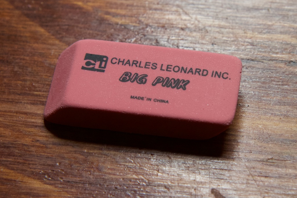
There’s no way this is going to work.
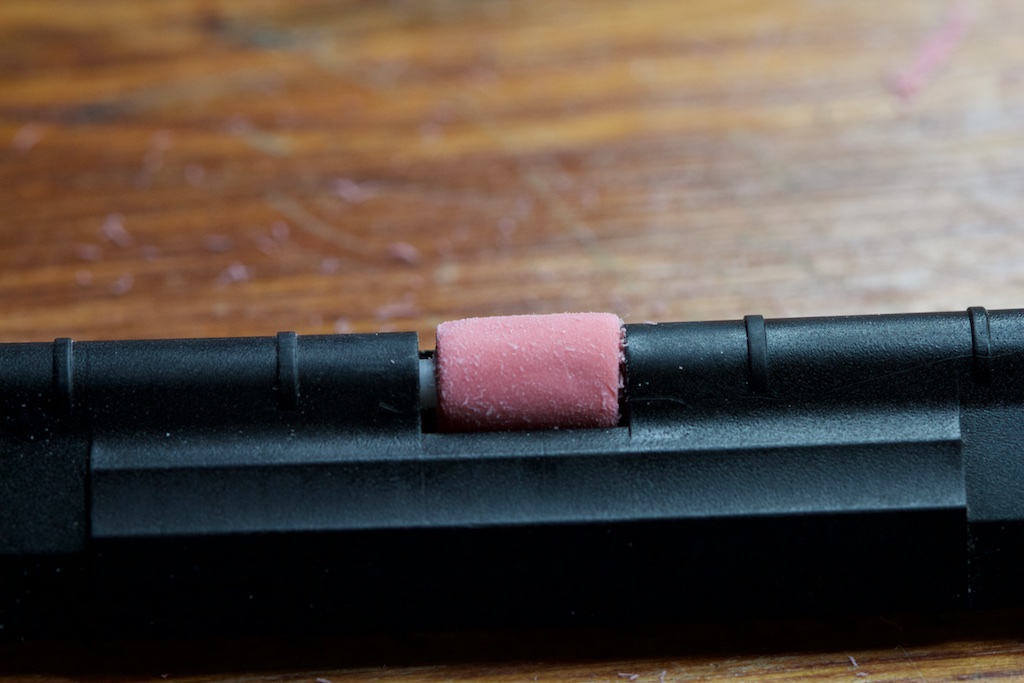
I had a few large rubber erasers left over from that time that I spilled a bunch of graphite powder on my kitchen counter and couldn’t think of a better way to wash it off. It actually worked for the most part:
I suspect that an eraser won’t be as durable as a silicone roller, but as long as my Aunt is careful not to tug on the paper, it could work. Besides, I don’t think she uses the printer function much anyway
So step one was cutting it down and drilling a hole:
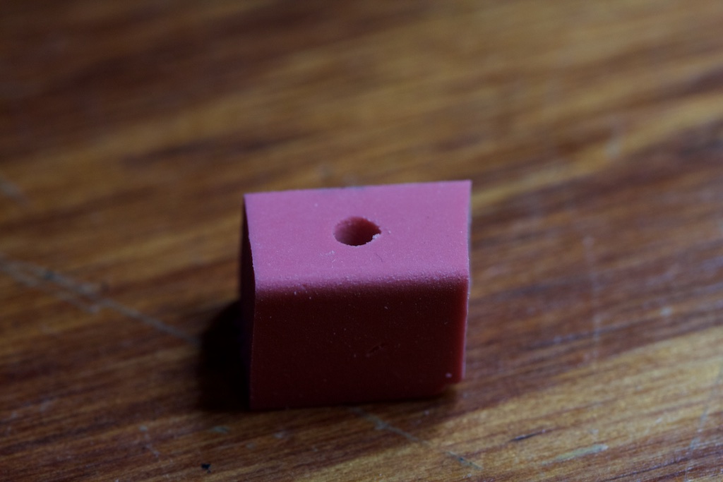
I drilled the hole to the inner diameter of the spindle. This means that the grippy teeth on the spindle would force their way into the rubber and hopefully find purchase.
Next up was shaving it down with a razor blade into something roughly cylindrical:
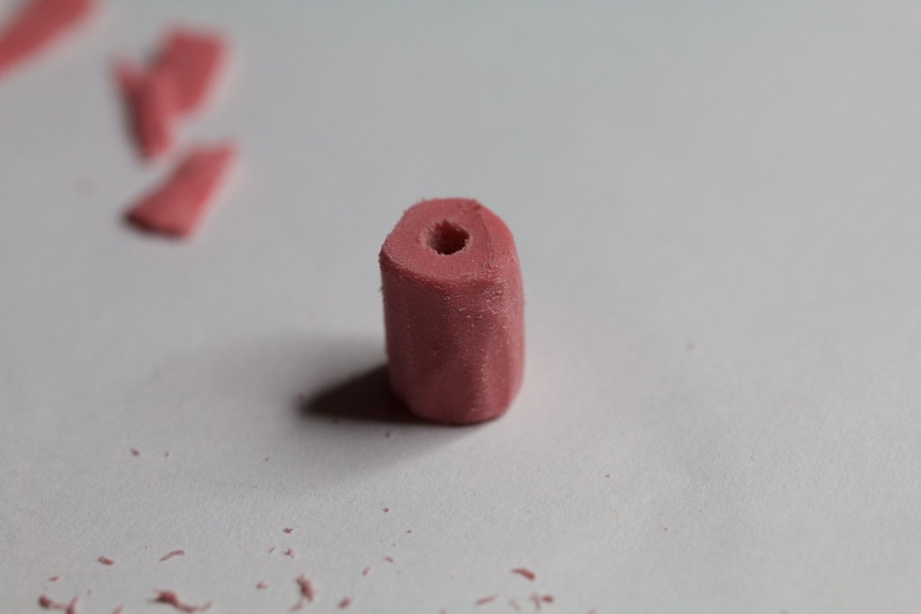
There is no way in hell this is going to work.
Once I got it small enough, I tried inserting it into the printer. This was a little risky since you can’t remove the spindle from the housing without also removing the roller. I wanted to avoid forcing the spindle into the roller too many times.
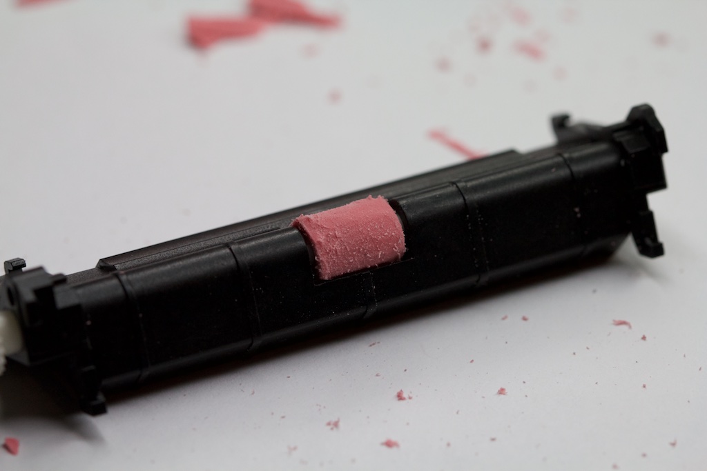
The roller was still way too big to rotate, but fortunately, you can sand down rubber erasers with normal paper!
I think my estimate for the roller’s size would have been far too big had I gotten the silicone rubber thing to work. I believe the roller was designed to sit more or less flush with the surrounding housing. With the roller sanded down to an appropriate size, it was time to snap everything back together:
And now to test it.
Testing and conclusion
It worked! There are very few times when I feel like I really live up to my blog’s slogan. Shaving down a rubber eraser to fix a forty year old calculator is now one of them.
I really love the way this thing sounds. In today’s electronics, making things faster often involves making them use less power so they don’t overheat. Back in the day, the solution was to just dump more and more current. That’s how you end up with this:
The motion and sound of the print head dancing around is almost violent in how quick and noisy it is. I can only imagine what an entire office full of these things would have sounded like.
And there is something to be said for how easy it was to repair. I recently busted an iPad that was scarcely four years old and had to resort to selling it on eBay for parts. Meanwhile, this ancient calculator just needed another few cents worth of capacitors.
That being said…
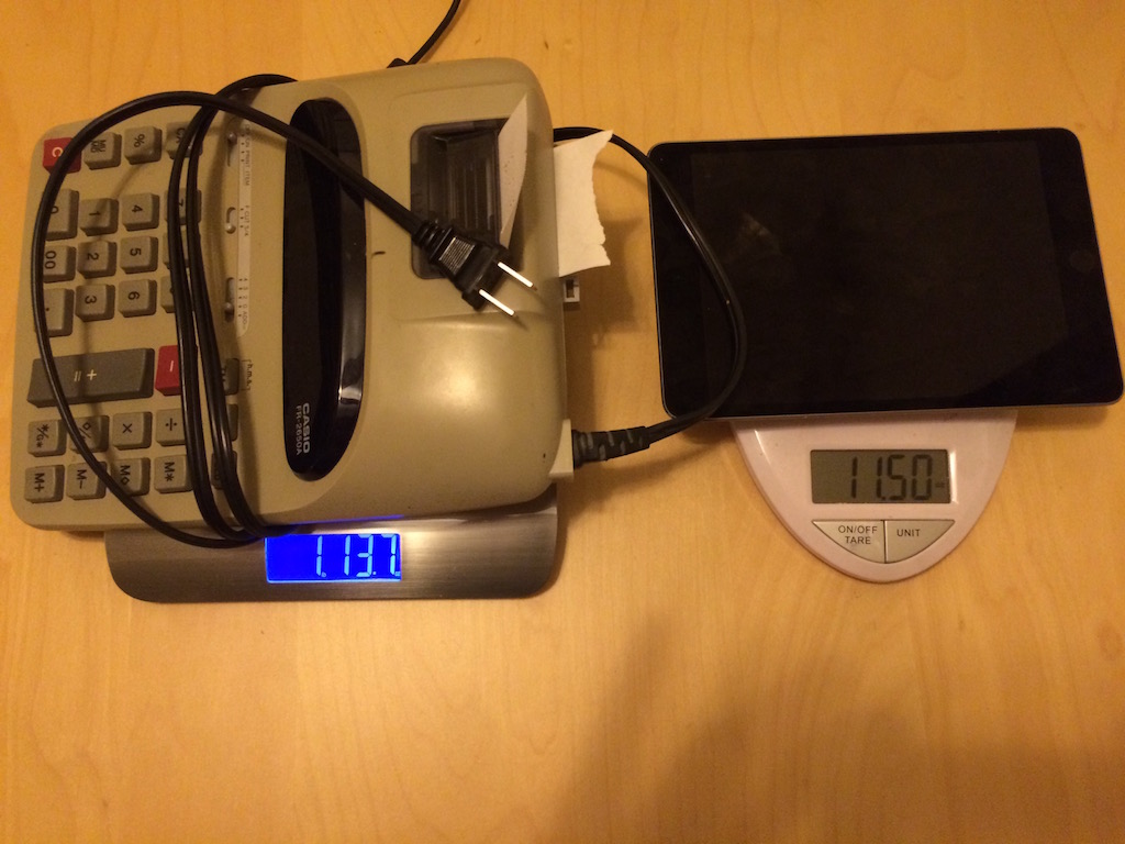
The future is pretty great.
Update
After returning home from my visit with the family, I woke up to another email from my aunt:
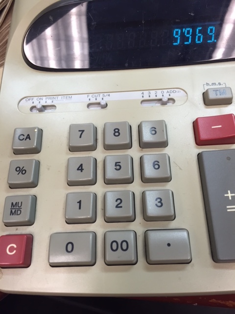
Subject: You are killing your old Aunt dude!
Do you notice anything funny about the key board??? You put the 9 on upside down so it looks like a six. Screwed me all up until I figured out what happened. I am too old…. it works fine and as long as I don’t look at the keyboard I’m cool, but if I look I get all kinds of confused.
Can I just pop it out and turn it around?
Thanks! Aunt Saundra
Whoops!
Pingback: 2 – Electrolytic capacitors and preserving a family heirloom
I got a kick out of how you chose to fashion a rubber feed roller out of a block pinky eraser. A quick run to the store might have saved you a bit more trouble. This was my solution to a similar crafting problem:
http://imgur.com/a/eD9cW
Nice post – I picked this up from reddit.
There’s something very satisfying about taking an old piece of electronics equipment and giving it a new lease of life. In this day and age it has become socially acceptable to simply throw things away and buy another one.
It’s worth hanging on to old retro kit like this. One day, it might be worth some money. You never know!
Regarding the bad capacitors, in addition to the drop in capacitance I imagine that the ESR will have significantly increased as well. They will have become very poor capacitors indeed. A capacitor with high ESR drops a lot more voltage, and hence the power supply no longer functions properly.
If you have a signal generator you can hook up a quick circuit with your ‘scope and measure the ESR. See this blog post for more information:
http://brianhoskins.uk/jvc-th-s5-diagnosis-and-repair/
Thanks again for the great post, I shall keep an eye on your blog in the future!
Cheers,
Brian
The board near your two filament resistors is heat damaged. Now that you have bypassed one of the resistors in series with the filament the other will be dissipating more power.
I’d suggest replacing your remaining 20-ohm resistor with a pair of 20-ohms in parallel and the jumper link with another pair of 20-ohm resistors in parallel. This will give you the same equivalent resistance as what you have now and it will spread the power dissipation over a much larger area, hopefully avoiding more board damage and (more importantly) fires.
I suspect the designers didn’t know exactly what resistance they would need in series with the filament when designing the board, or they expected to have to change it during production (eg the VFDs may have had a big variance between batches or different brands were used). Having a couple of spots to put resistors means you can get away with higher power dissipation in the resistors without needing to opt for (more expensive) larger ones.
I’m not sure why they chose the layout of one resistor on each end of the VFD. Perhaps the designer had style, perhaps it was convenient on the single-sided board.
Also: I hope Saundra is really happy with what you have done 🙂
None the less, as a government worker concerned for her calculator: please fix her fiery resistors. She may be happy to lose the house, but if the latest report _and_ the calculator go then everything is lost.
I noticed that too, but after running the display for a few minutes, those resistors weren’t even warm to the touch. I suspect heat was responsible for darkening the board, but it must have been a very small amount of heat over a very long career. I estimate about 320mW of heat dissipation across the remaining 17 ohm resistor, and I’m pretty sure it’s rated for half a watt based on its size.
Regardless, I’ll tell my Aunt to be on the lookout for any suspicious smells. Thanks for your concern.
Pingback: Ultrasonic parking sensor | ch00ftech Industries
Pingback: Repairing a 42-year-old Calculator « Adafruit Industries – Makers, hackers, artists, designers and engineers!
I repaired these sorts of calculators in the 70s and 80s. You did right.
The caps do age, and replacing them is the first thing. But the VFD is also aging, and will darken over time. Reducing the resistor values to increase the drive is a stopgap. The values were chosen carefully, be assured.
Casio used fairly conventional power supply designs, unlike some other makers. The heating on the PCB is the result of 40+ years use, fear not.
The eraser hack is cute, but not new. I used to force one on and chuck the shaft in a slow Drexel to spin it down to a good size. It will last for another 40 years maybe.
Good job!
Have you ever tried this sex game before? GIVE IT A TRY: http://inx.lv/GkWu?h=e1d820b904636d15015eb265e53ea770-
t5mfnc
Pingback: Smart ParkGuard: Developing an Ultrasonic Parking Sensor system
b4blo4
g2ptih
6j41mn
j6de69
06gpgl
o0xjez
7om887
krvi23
5xd7kf
s2iiww
ywjp62
x6ee9d
xyunow
lglz82
fwfmng
1lulzr
b0w2vd
ccb78d
of5s8b
77752m
0cjthk
lvll1w
jl1p8h
ep2edw
5zgr2t
uvxppy
r8ma6f
c3k0fw
cj2jwe
9w4aus
ukpy66
r63aot
yywty5
faz5da
h8xusz
kdln3b