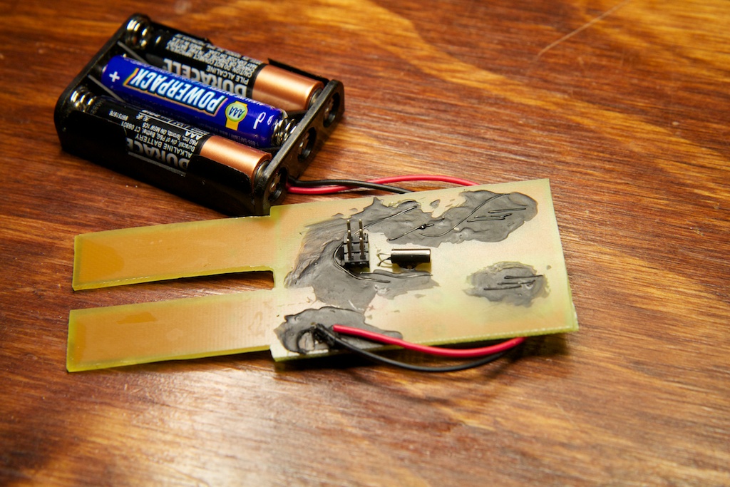
My friend has trouble keeping plants alive, so I made her this!
Motivation
In the June 2012 issue of Nuts & Volts, they did a spread about making a soil moisture sensor with an iPhone interface:
And when I heard my friend say that she has trouble remembering to water her plants, I put two and two together.
Most of the N&V article discussed the code required to interface with the iPhone, but the important part for me was that their soil moisture sensor was nothing more than a simple conductivity sensor. The more water in the soil, the lower its resistance.
Such a sensor doesn’t measure soil moisture in any kind of universal unit, but for a single sensor in a particular soil sample, the measured conductivity is repeatable and proportional to the moisture level. I call these conductivity units “AMU”s or “Arbitrary Moisture Units”.
Objective
So I wanted to create a device that reminds her to water her plant when it gets dry. Such a device needs a user interface where she can set her AMU threshold and an alarm to alert her when the plant slips below that. It also needs to read out the current moisture level so she can know where to set the threshold. Simply taking a measurement before and after watering should provide good basis for determining threshold.
Once set, the device needs to stay put; moving it in and out of the soil will make it very difficult to get the same AMU reading twice. Besides, if she could remember to insert the sensor on regular intervals, she wouldn’t have trouble watering the plant in the first place!
Leaving the sensor in place offers a interesting challenge. For the most part, this device doesn’t need to do anything. Soil moisture changes extremely slowly, and anything over a .1Hz sample rate is hardly necessary. Also, the device needs to stay on for months or even years at a time. Plugging it into a wall is inconvenient if there isn’t a wall outlet near the ideal plant spot, so the device needs to be battery powered. The question is, how do you get batteries to last for months or years?
Another sub-objective of this project was to make it happen entirely using parts that I already had on hand.
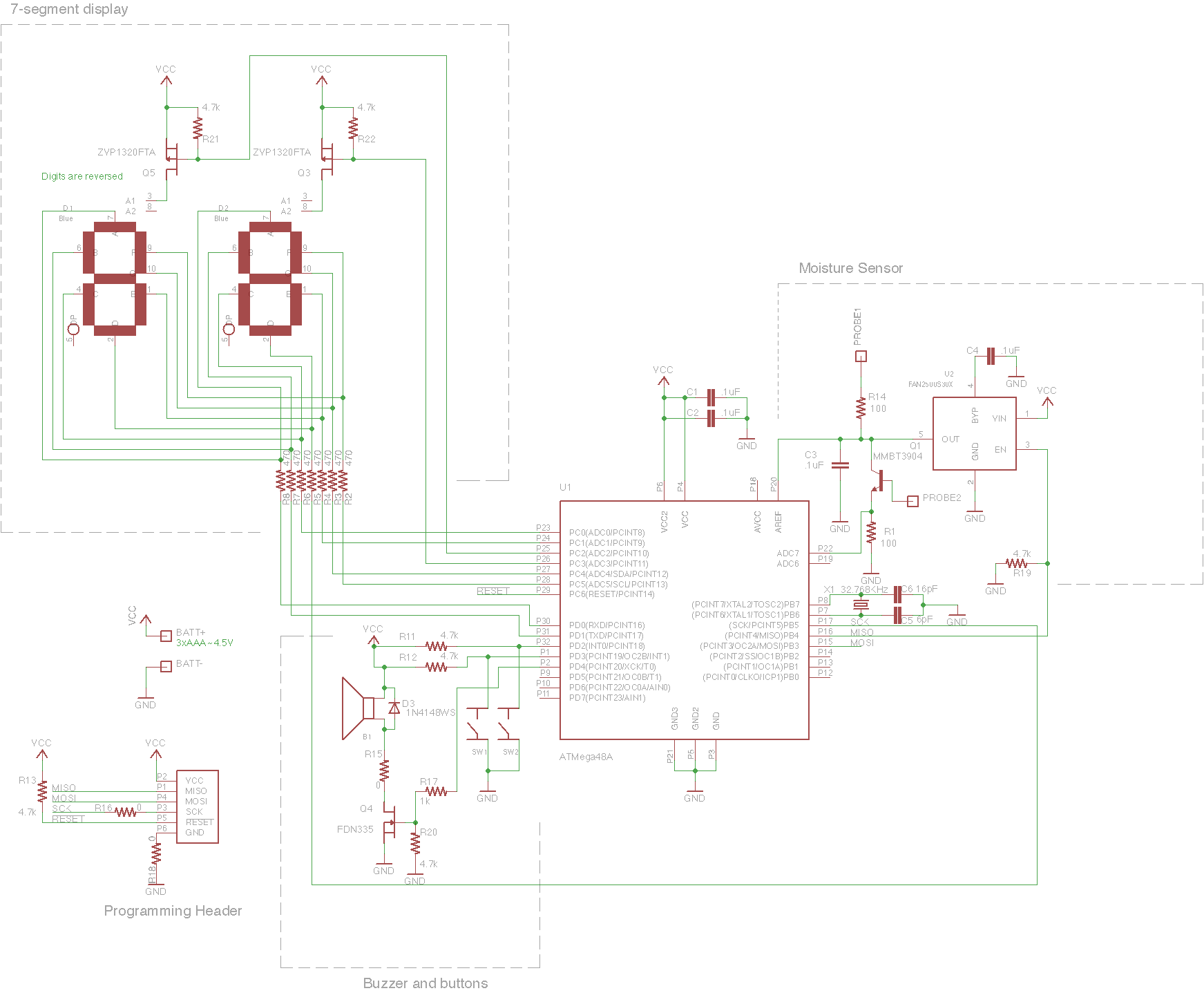
Schematic
Display
The display is a multiplexed pair of 7-segments LED modules. I had some left over 7-segment displays from a commissioned piece that ended up falling through. They’re from Mouser, and as beautiful and blue as they are, at  \mu$A of current when in shutdown mode which is small enough for my needs.
PCB
Because of the complexity of the displays, this circuit required a lot of vias. I decided to try out my new .0135″ drill bit which worked like a charm. To give you an idea of how small this thing is, here’s me picking Lincoln’s nose on a U.S. Penny:
This thing was so small that I could only thread the holes with a single fiber of copper from a stranded piece of wire.
I used the liquid electrical tape from the Strongerer Glasses to protect the fragile unshielded copper strands and keep them from shorting together.
This is also the first project where I’ve laid parts out at a 45 degree angle. It just turned out to be easier for this particular layout. Getting Eagle to do it is kind of tricky though. The program by default will only rotate a part in multiples of 90 degrees, so I had to manually type in the angle of 45 and then let it rotate at 90 degree intervals starting from there.
The two sensor prongs are just giant exposed copper planes. Ideally, I’d coat them in something that both won’t corrode and won’t poison the plants, but I don’t have anything like that on hand at the moment. Can you say proof of concept?!
Firmware
Many of the elements involved in writing this firmware are things that I’ve done before in other projects with a few exceptions.
User Interface
The device only has two buttons which are assigned to “up” and “down”. When initially powered up, the device displays the current AMU reading. Pressing the up or down button will temporarily display the threshold value and allow you to adjust it. This is the kind of interface I’ve seen used in some thermostats, so it seemed appropriate.
Leaving the buttons alone for about 1 second will cause the display to switch back to the AMU reading, and leaving them alone for 30 seconds will put the device to sleep where it will wake up periodically to take measurements and beep if the moisture is too low.
Pressing either button immediately wakes the device up and sets it back to the original mode.
Tone Generator
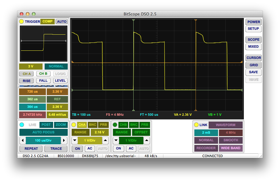
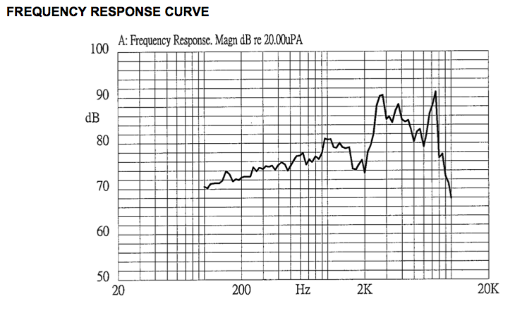
The buzzer component needs a square wave of frequency 2.73kHz. To generate such a tone, I used Timer1A configured as a CTC timer. This means that the timer increments until it reaches OCR1A and then resets while triggering an interrupt. This interrupt only toggles the output pin, so I actually had to generate twice the desired frequency (5.46kHz).
With a base clock of 8MHz and a 1/64 prescaler on Timer 1, I set OCR1A to 23. That works out to:
![]()
Which when divided by two gave me a square wave output of approximately 2.747kHz.
Not exactly 2.73kHz, but as you can see on the datasheet:
There’s a small flat zone around the optimal point, so I should be fine.
Power-Save Mode
Getting the power draw of this device down to as low as possible was the biggest challenge of this design. I’ve done a few experiments with sleep-mode devices before, but most of my projects are woken up by a user pressing a button. This device needs to wake itself up to take periodic measurements of the soil. I’ve only done this once before, and that was for a quick demo on a breadboard and was like a billion years ago.
With an external low-power 32kHz crystal, the ATMega48 can go into “Power-Save” mode where it shuts down just about everything except for Timer2 which counts in time with the external oscillator. Once this Timer2 overflows, the device wakes up to handle the interrupt and stays awake until it’s told to do otherwise.
Given that soil dries out on a time scale of the order hours instead of seconds (or milliseconds), the device needs to stay in Power-Save mode as much as possible. In order to extend this time, I configured Timer2 to interrupt on overflow (256) with a 1/1024 prescaler. This sets my sleep interval to:
![]()
So every 8 seconds, the device wakes up. I designed the software to immediately go back to sleep unless a certain number of 8 second intervals have already passed at which point it takes a measurement of the soil and beeps if it’s too dry.
I noticed an interesting bug during development where it seemed to ignore this programmed number of intervals and take a measurement earlier than it was supposed to. It was always earlier in multiples of 8 seconds, but always some arbitrary multiple.
I soon discovered that my device was actually waking up, updating its current count of 8 second intervals, and then going back to sleep all before the 32kHz clock ticked once! Because the 8MHz clock is so much faster than the 32kHz clock, it’s perfectly possible for the device to go back to sleep before the next 32kHz tick. The flag that wakes up the microcontroller is still set until that next tick, so just as it woke up the first time, the part will immediately wake up again as soon as it goes back to sleep.
Unfortunately, there’s no way to directly determine when the next clock tick happens. I could have my code wait in a delay loop for a specified amount of time, but as it’s burning battery every millisecond it’s awake, making this delay any longer absolutely necessary is inefficient.
To fix this, I found a neat tip on page 156 of the ATMega48a datasheet. The ASSR register is provided to deal with many of the features of an asynchronous clock (the 32kHz clock is asynchronous). There are a few bits of the register that indicate when changes to clock settings (TCCR2x, TNCT2, etc) go into effect. They always go into effect on the next clock edge, so by changing one of those registers and then waiting for the proper bit of the ASSR register to change, I can indirectly determine when the next clock edge has occurred and it’s safe to go back to sleep. Of course, the registers are already set where I want them, so I just had it redundantly set a register to its original value.
On the way to solving this issue, I also realized that leaving my ADC on causes the device to draw substantial power (.3mA) even while asleep. I thus changed my code to only enable the ADC while taking a measurement.
With all of these precautions in place, the device draws an incredibly low amount of power while in sleep mode:
Assuming the average AAA battery has about 1000mAh of capacity, that’s going to give you over 15 years of use. Now, the device does have to wake up every 8 seconds to do its thing, and it’ll draw even more power if it has to run the buzzer to let you know the plant is dying, but these operations take a very short period of time (a number of milliseconds at the slowest), so the user can at least expect a few years of use before having to replace the batteries.
Conclusion
So nothing terribly ground-breaking with this design, but it was a quick and fun refresher, and I learned a few more things about the different power down modes of the ATmega48.
It’s also a surprisingly practical device coming from me. I can’t wait to hear what she thinks of it once she puts it to use!
Project files can be found here: Soil Moisture Sensor v1.0


This is a really neat project, I really enjoyed this one because it’s a problem that I solved for myself and I’m always curious to see how different people approach the same problem!
I have one plant that’s inconvenient to reach, but I don’t have a problem remembering to check my plants periodically. I needed a device for one plant that would let me check on it from a distance.
I ended up with a very similar concept, but with fairly different execution:
– Instead of building probes into a PCB, I just have screw terminals and run wires to a pair of three-inch nails that are stuck into the soil.
– I used all through-hole components and cut down a piece of perfboard to the desired size, I’m not sophisticated enough to make my own boards yet.
– My UI for changing the amount of moisture before triggering consists of moving the probes closer together or further apart. Which is to say there is no real UI for this.
– My UI for checking on the device consists of two LEDs – the green one flashes every 10 seconds or so as a heartbeat and every second or so when the plant needs water. The red LED is used to indicate a low battery or an error condition.
– The microcontroller I used is an MSP430 from the LaunchPad kit – it’s perfectly happy to run from two AAA batteries without a regulator. I’m using the internal oscillator on the MSP430. I measured the current draw at 0.4uA when sleeping and about 1mA when taking a measurement – this is done when the heartbeat LED flashes, so this is the most power-intense piece of code.
I put a lot of thought into the probes. I was concerned that there would be the potential for corrosion, so my probes are connected as a voltage divider with the middle going to an ADC input and the other two ends going to output pins. In my sampling routine I run the current through it in both directions a few times and average them out. If two readings in quick succession don’t add up to close to 1024, that indicates that the probe is only passing current in one direction and triggers an error condition. I’m not sure where this would happen in the real world, but on the LaunchPad there is an LED connected to one of the pins I was using and this caused that situation. 😉
Wow – great job! Your surface mount component and PCB skills are far beyond mine.
Like MisterSnuggles, I also tackled this problem slightly differently. I used a pair of nails in Plaster of Paris – the gypsum only conducts electricity when wet. Also, I needed mine for outdoor use (I’m checking the moisture level of the lawn at different points to decide if I should turn on the irrigation system) so I needed a probe that could be connected over a long wire. For protection, I used an opto-isolated transistors to control the probes to avoid damage to my computer in the event of a power surge from a lightning strike (which happens more often than I like). Here are the details and pictures:
http://bithead942.wordpress.com/2011/05/24/automated-irrigation-system-take-1/
Hi,
nice project, but one thing bothers me. When you run DC current through soil and electrodes it will decompose this metal electrodes. And havy metal goes to soil and your platns. Hop you don’t eat them!
BR
You’re absolutely right. Even without the electrical current, one can expect copper to decay when exposed to moisture and water. This is definitely a proof of concept. If I wanted to make it last longer, I would need to plate the electrodes in something inert like gold.
Great project, always good to see how others do it. I was especially intrigued by your circuit around the probes.
Just out of curiosity I did some calculations around it and found you are more or less on the ball.
if the soil is wet enough, you would expect your highest reading of 3 volts. In order to get that on a 100 Ohm resister, a current must flow of 30mA.
As it is an emitter follower, the base must be able to deliver such a current, fractioned bu the Hfe.
The 3904 at 30mA Ic has an Hfe between 100 and 60, lets say 80. therefore the base must be able to supply 0.375mA.
provided that at a wet soil, the resistance is about 10k (true, depending on soil type and distance of probes).
In order to have 0.375mA flow through 10k (neglecting the two 100 ohm resistors), you would need a voltage of 3.75 volt ( neglecting the 0.7 volt Vbe), so truthfully 4.45 Volt.
As your probes are quite close together my 10k was probably a bit high, so I’d say you are right on the ball here, but peopel rebuilding this might want to be careful in putting the probes too far apart.
With regard to some people using gypsum probes… I have done that and had disappointing results. They easily dissolve after a while + they react kinda slow.
As far as the corrosion goes… I stayed away from copper but used galvanized nails and only switch on the current a few times a day. I experienced that they needed little correction of the level due to corrosion and I just clean them after a growing season.
As regard to someone warning for lightning strikes generating a spike in long wires that could damage the circuit.. that could very well be true. Long wires somehow can generate spikes anyay also with no noticeable lightning, but apparently even with thunderstorms building in the distance. Rather than an optocoupler I opted for a 5.1 V Zener at my uP ports.
I have built things like this with opamps (a 741), an attiny85 and an Atmega 328. As I use them to directly drive a pump, I needed power in the surrounding anyway so I didnt bother with solar or batteries as some people do.
Great project
hey,
Your project is great and your designing skills are awesome. Can you please publish the updations on the blog that you have done after the publication? It would be greatful.
Thank you