So I realized this morning that I’m not going to have quite enough I/O pins to drive all of these LEDs. If I set it up like this:
Then to get 132 LEDs (60 mins, 60 seconds, and 12 hours), I’ll need a 11×12 grid which will require 23 ports, much more than the ATmega48A has to offer.
Alternatively (and I’m not sure if this will work), seeing how LEDs only pass current in one direction, I could also arrange them like this:
This will double my LED capacity. With this setup, I would only need a 9×8 grid requiring just 17 I/O ports. The ATmega48A has this many ports, but a lot of them are tied up doing other things:
- PC4 – SDA (part of the I^2C interface)
- PC5 – SCL (part of the I^2C interface)
- PD2 – INT0 (external interrupt)
- PC0 – ADC0 (analog-digital converter required for reading the accelerometer)
- PB6 – TOSC1 (needed for RTC crystal)
- PB7 – TOSC2 (also needed for RTC crystal)
This leaves me only 16 ports. The last two might be optional though. If I get the external RTC unit working properly, then I will only need the I^2C interface to talk to it and I can free up TOSC1/2.
I shouldn’t be needing any more inputs as my Interrupt pin can be reconfigured upon waking as a simple input port to accept user button-presses (remember, only has one button).
So all in all, this is a tight squeeze, but assuming I didn’t forget anything, it should work.
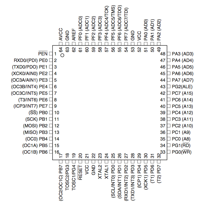
My fall-back plan is to upgrade to the ATmega128A:
This mofo has a metric butload of pins and is still only .6 inches to a side. I don’t really think this sets me behind though because this dude is surface-mount only and has similar features to the ATmega48A, so once I get my prototype code working, I can work on porting my code to the bigger chip.
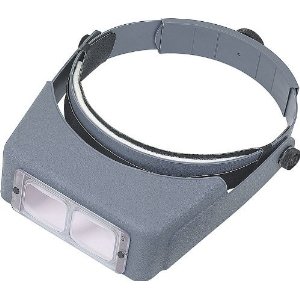
Also, I purchased a set of these last night:
I’m stoked.


