Good bearings

So, I finally figured out what the deal was with my accelerometer needing to be asked twice what the value was.

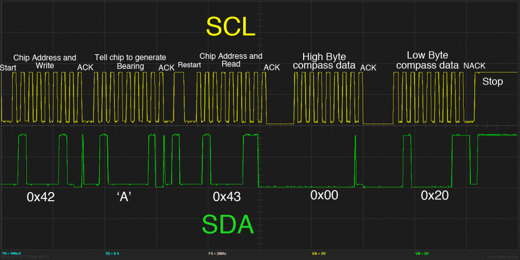
As it turns out, I wasn’t actually giving the chip time to reply. I thought the micro would automatically handle receiving the data value, so I all I had to do was send the ACK at the end. In fact, the command that sends the ACK actually tells the micro controller to wait until the entire data byte has been transmitted, and then transmits the ACK.

So, when I was storing the value before sending the ACK, I was storing the value that I originally had in the register (the address of the accelerometer chip) and then waiting for the data and finally sending the ACK. Now, I’ve changed it so that it waits for the data and sends the ACK before storing the data value in the register.

How did I figure all of this out? With an O-scope! I simply modified my code so that it would give me a voltage spike on one of the output pins while it was reading the data from the register. What I noticed was that it was spiking before it was supposed to. Here’s an example of what I mean:

 

Continue reading

Punctual, but Problematic

So, you haven’t seen an update out of me in a while. This is because I’ve been struggling over the past week with getting my clock to return accurate, or at least consistently inaccurate results.

My test method was to use a little program that I wrote that would give me a 10 second count down before starting a timer that increments the LEDs once per minute. The idea was to use the 10 seconds to synchronize the timer with a timer known to be accurate and then let it run for a few hours and see how far off the minute mark it was. Take the number of seconds it’s off, divide by total number of seconds elapsed, and multiply by 1 million to get the parts per million (ppm) accuracy.

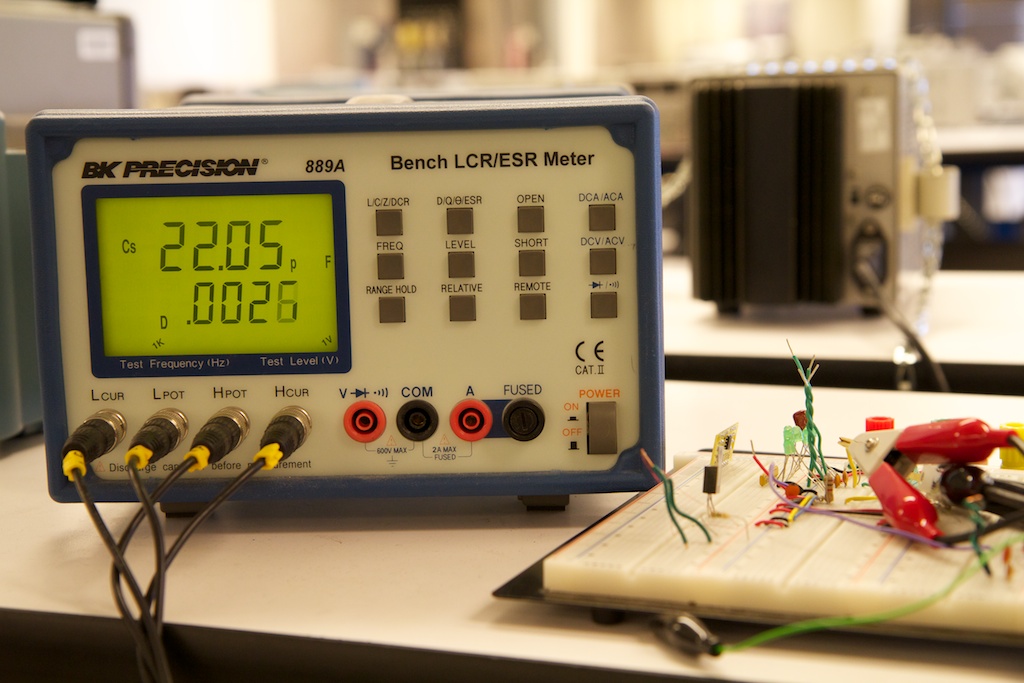
See, every crystal oscillator needs to be “tuned” with some Load Capacitors. I tried my best to match the Load Caps to the 22pF rating on the crystal’s spec sheet (even taking into account the parasitic capacitance on the breadboard), but I still couldn’t get good results.

Me and the Cap’n

So, it turns out that clock crystals need a “load capacitance” between each of their two pins and ground. I’m not entirely certain what these capacitors even do, but I do know that they are critical to keeping good time.

That nixie tube clock that I made originally had a clock crystal in it that had no load capacitors. This resulted in it being inaccurate.

Tik Tok

I have a clock!

So last night/today, I worked on getting the clock part of my AVR working. Here’s the basic rundown.

The ATmega48A has what’s called an asynchronous timer. A timer usually works by simply incrementing a number on a fixed interval of time and doing something special when that number reaches a certain value. Most of the time, the timer will just increment every time the processor’s clock ticks. An asynchronous timer is special in that it can clock along at an entirely different pace.

While the processor is chugging along at 8MHZ, my clock timer is clicking along at 32.768kHz. How do I know this? Because I have it connected to a 32,768Hz clock crystal. Why such an odd number? Lemme explain.

Dearly Departed

So today was something of a downer.

I received my LGA-16 breakout board from proto-advantage.com yesterday, and decided to give reflow soldering another shot with my digital accelerometer, the LIS33DE.
The LIS33DE is the first 3V chip I’ve used that cannot also run at 5V. Because of this, I decided to re-do my breadboard and get myself a 3V power supply. I found an old PC power supply that can output 3.3 volts which is close enough. I’ve got some mounting posts that I’m planning on bolting to the power supply to make it a little easier to manage, but for tonight, I just used some alligator clips to bring the 3.3V to my board.

Now, along this process, I did a very stupid thing. I left my micro controller and temperature probe connected to the board. I’ve always been a fan of hot-plugging in the face of adversity, but in this case, I was a little too reckless, and not only killed another micro controller, but also the temperature probe!

Luckily, I had backups of both, and while desoldering a SOIC part is tedious, it’s by no means impossible.

I think I’m thinking too hard

I’ve been pondering this current-limiting nonsense all day, and I think I’m overthinking.

The issue is this: If I want to get maximum brightness out of my LEDs, I’m going to want to overdrive them a bit because I can run them at a maximum of33.3% duty cycle (if I have three LEDs lighting up at the same time). LEDs that are rated for 20mA of constant current might be rated for up to 100mA of peak current. Apparently, nobody make a 40+mA constant-current LED driver that runs at 3V. Oh well. Continue reading

A greener watch

I’ve been thinking more about energy savings with my watch.

I’m already going to be using some kind of Real Time Clock chip so that it only draws a tiny bit of precious power from my battery when in standby, but what about when I power the thing on?

Well, LEDs aren’t current limiting. This means that unless you do something special, they’ll draw a ton of current (and if you supply them with enough current) blow themselves up or at least severely shorten their lifespan. Because of this, you always need to add a current-limiting resistor to protect them.

Here’s how it works: Continue reading