So, it turns out that clock crystals need a “load capacitance” between each of their two pins and ground. I’m not entirely certain what these capacitors even do, but I do know that they are critical to keeping good time.
That nixie tube clock that I made originally had a clock crystal in it that had no load capacitors. This resulted in it being inaccurate.
Well, it isn’t obvious from this video, but over the course of a day, it would lose 2 minutes of time or so. I ended up fixing the problem the lazy way and just used a “Crystal Oscillator” which is a three terminal device that takes Vcc and Gnd and gives you a pretty square wave. All of the load caps and everything are built in. Unfortunately, these guys are too big to fit in a watch, so I still have to figure out what the deal is with these load caps.
I’m getting a couple conflicting answers. Here’s what the AVR data sheet has to say:
In the table above, it lists Ci as 18pF on tosc1 and 8pF on tosc2. I read somewhere that you can typically expect stray capacitance to be around 5pF or so, and the clock crystal’s data sheet lists CL as 12.5. This makes the value of Ce around 0pF for tosc1 and 12pF for tosc2.
Hrm…
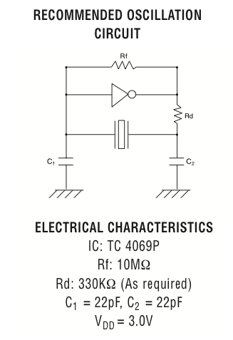
What does the crystal’s data sheet have to say?
Soo… I’m pretty sure I can ignore the Rd because it’s “as required” and my AVR data sheet makes no mention of a resistor like that.
So, this is a little ambiguous. I’m really not certain what to do. I think I might just follow the crystal’s data sheet because the math for the AVR’s data sheet is really weird. Besides, I’m fairly certain these capacitors won’t saturate, so using bigger caps (like the 22uF) can’t do too much damage, right?


