So, keeping up with my newly rekindled obsession with dimming my EL panel, I decided to try dimming with a TRIAC.
It didn’t work.
Introduction
Before talking about why it didn’t work, let’s talk about how it works.
TRIACs are TRiodes for Alternating Current which means that they’re electrically controllable switches for AC currents. I’ve used TRIACs before in my EL wire glasses where they turned EL wire on and off to the beat of an audio track.
In that case, I was switching them rather slowly compared to the frequency of the AC signal going to the wire. They acted as an “all or nothing” switch. They either supplied the AC waveform in its full glory, or they supplied nothing. If you’re clever though, it’s possible to get TRIACs to transmit a modified AC waveform, but to do that, you need to understand a little more about how TRIACs work.
Deets on the TRIAC
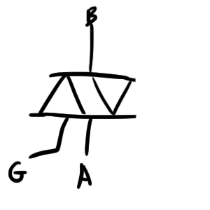
So, I’m not going to get into the inner workings of a TRIAC, but I will tell you how one behaves in a circuit. A TRIAC looks like this:
It has three terminals. The basic rundown is that when current is pulled out of or pushed into the gate (G), the TRIAC turns on and allows current to flow freely from A to B or from B to A. Given that, you might assume that the TRIAC will turn off as soon as you stop the current flow through G. You’d be wrong.
TRIACs are only really useful for AC because given a DC signal, they will not turn off no matter what you do to the gate. A TRIAC will only turn off once the current through it drops to zero (or below some threshold close to zero).
While this might seem like an annoying and arbitrary setback, it’s actually kind of convenient for attenuating an AC signal.
Attenuating AC
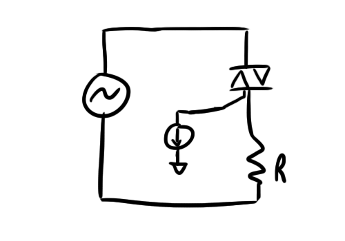
So let’s say you have your TRIAC set up in a circuit like this:
I’ve drawn the current source on the gate so that we can ignore the particulars of what kind of potential difference is required to generate this current.
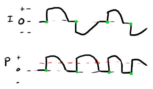
Assuming that current source is on, the TRIAC will be fully conducting and act like a wire. You can expect that a sinusoidal voltage waveform across the resistor will generate an in-phase sinusoidal current. The current and power waveforms for the resistor might look something like this:
Remembering that power
![]()
, the instantaneous power will look sort of like a sine wave that’s all positive. If you take the area under this curve, you have units of Power
![]()
Time which is Energy. Take the Energy and divide by time and that gives you average power which is represented here in dotted red.
So let’s say you build a really clever switch and put it between your TRIAC and your current sink:
This switch is clever because it keeps an eye on the zero crossings of the AC signal and only closes for a brief moment a fixed amount of time after a zero crossing.
Keep in mind that the switch is only closed for a very brief moment when you see a green dot. It stays open the rest of the time.
So every half cycle, the switch waits for the zero crossing. Once it sees a zero crossing, it starts a short timer, and when that timer runs out, it closes for an instant. The timer can be anywhere between zero and T/2 seconds long. If it’s any longer than T/2, it won’t have a chance to close before the next zero crossing.
So what does our resulting current and power waveform look like? Keep in mind that the TRIAC will not conduct current until it gets a gate pulse from the switch at which point it will conduct until the current through it is zero.
With this change, the area under the power waveform is reduced. This reduced area means a lower average power (indicated again in red). If you make the timer on the switch longer, you will get less power delivered to the load and if you make it shorter (or zero), you will get more.
So this is a pretty ugly waveform to feed to any kind of sophisticated equipment, but if all you’re worried about is power delivery to a purely resistive load (like a tungsten lightbulb), then this works just fine.
The other cool thing is that before the switch pulses, the TRIAC looks like an open circuit, and after it pulses it looks like a short. During both of these conditions, you get little or no power dissipation from the TRIAC. This means that you can dim your lights all you want without having to worry about losing efficiency or heat dissipation. Almost all of your power is being delivered to the load. This makes TRIAC dimmers suitable in dimming light switch applications.
My Implementation
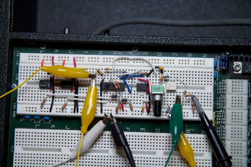
So I had an idea to try using a TRIAC with a “magic switch” on my 1200Hz, 120V EL power supply to control my EL panel’s brightness. This would be a great solution because if it worked, I would have little or no power dissipation in my circuit and a very high efficiency.
Unfortunately, it didn’t work. This wasn’t due to a fault with my circuit design, but rather a result of the peculiar load an EL panel presents to a circuit. With a purely resistive load (like a resistor or light bulb), my implementation works just fine. Because of this (and because I’ve never written about it before), I think it’s worth explaining exactly how my “magic switch” works.
Magic Switch
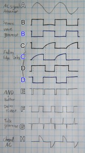
So I think it would be easiest to explain this circuit by first presenting a schematic and waveform and then talking about it step by step. I recommend clicking next two images and opening them on separate windows so you can follow along while you read:
AC ATTENUATOR
This section is fairly straightforward. None of the parts on my circuit are rated for 120V, so this simple 1/101 voltage divider gives me a nice voltage waveform that stays below 2V. Although there really isn’t a “positive” or “negative” terminal on an AC source, I included those indicators to make it clear how the AC supply is hooked up. This is the same supply shown again at the end of the circuit powering the load. It’s important that the (-) terminal be connected to ground in both cases.
The output of the divider is represented by A.
Square wave generator
The toned down waveform is quickly passed into two comparators. Because the AC waveform is centered around ground, these need to be dual-supply comparators that can handle a negative input voltage. I was lucky enough to have a negative voltage supply on my lab kit.
These comparators compare the waveform to 0V. The idea is that their output will be square waves that have edges at every zero crossing. Also, they will be opposites of each other because ground is hooked up to the inverting input of one and the non-inverting input of the other. The output is B. I used an LM311 which requires a pull-up resistor on the output. This is what R3 and R4 are for.
Because the signal is split in two during this section, I color coded the two paths in black and blue.
FALLING EDGE DELAY
My first idea was to simply AND these two signals together so that the output would go high for a split second every zero-crossing (i.e. after one had risen but before the other had time to fall). Unfortunately, the signals were too good and this overlap never occurred, so I had to force it to occur with a delay.
Every time there’s a rising edge on one of the inputs to the inverters (U2A and U2B), the (inverted) output will fall rapidly as the diodes D1 and D2 quickly pull current out of the capacitors (C1 and C2). When there is a falling edge however, the diodes block the inverter from dumping current into the capacitor. The capacitor gets its current from R5 and R6 which deliver it rather slowly.
Because of this, you can see on the the C waveforms that the voltage rises very slowly and falls very quickly. This slowly rising signal takes longer to reach the threshold for what is considered a “high” input signal causing a slight delay on every rising clock edge.
The signals are then passed through another set of inverters which buffer and invert the signal giving you D. There are numerous places in this schematic where buffers could take the place of inverters, but I didn’t have any buffers on hand, so here we are.
Speaking of part limitations, ideally, C1 and C2 would be smaller. You only want the signals to overlap very slightly. If they overlap too long, you’ll have problems triggering the delay timer later on. Unfortunately, I didn’t have any values smaller than .001uF that weren’t ridiculously small, so I had to make do.
AND + Buffer
Now that these two signals overlap slightly, they can be ANDed together. Whenever both signals are high (overlap), no current will flow through the diodes and R7 will raise the input to U5A. When one signal is low however, its diode will pull current through R7 and lower the input voltage to U5A.
When this signal is buffered and inverted, you get E and we’re back to a single signal.
TRIAC DELAY TIMER
Now we’re on to the clock that will determine how much power we deliver to our load. This clock takes the form of a monostable 555 timer that is activated by a low-going clock edge in E. The delay time is adjustable using the potentiometer R8. For more information on setting up a 555 in monostable mode, check out the Wikipedia article.
Ideally, you’d set up your timer so that your potentiometer will give you the widest range between 0 and T/2. This requires you to know what your T is ahead of time.
A 555 timer in monostable mode will have an output that stays high until the timer runs out where it goes low. Passing it through another inverter makes it shoot high at the critical moment. That’s where you get signal F.
Pulse Generator
You might think that you’ll be driving the TRIAC with the F signal because it goes high at the right moment to trigger it, but this actually won’t work. The problem is that you want a short positive pulse and not a long positive period. This period only ends right at the next zero crossing. This doesn’t provide enough time for the TRIAC to shut down. Because some current will still be flowing through its gate after this zero crossing, it will be triggered for the rest of the next half-cycle.
This is solved by a simple high-pass filter provided by C4 and R10. This turns the square wave F into a chain of high and low pulses (G). The low pulses don’t do anything, but the high pulses turn on Q1 briefly which triggers the TRIAC.
OPTO-ISOLATOR, TRIAC, AND LOAD
An opto-isolator is like an LED and a phototransistor. The idea is that it takes an electrical signal and turns it into an optical one so there is no path for electrons to move from one side to the other and cause damage. This is a pretty good idea, because the gate of the TRIAC can reach some really high voltages.
In my explanation above, I had a current source driving the gate to make it simpler. In reality, the gate needs to have a positive or negative potential applied to it with respect to the A terminal (or whichever side the gate is drawn on). A quick and easy source for a different potential is the B side of the TRIAC. That’s why the gate is tied to the top of the TRIAC through the opto-isolator.
So lastly, you can see the voltage across the load, H. With a resistive load, the current will look very similar to this. For my load, I just used a fairly high-value resistor. Here’s a scope reading of H passed through a voltage divider to protect my scope:
Yay! It looks like it’s working!
So Why Didn’t It Work?
So, I wasn’t really thinking this thing was going to work when I set out, but I figured it was worth trying. At the very least, I’d get a cool blog post out of it RIGHT?!
The real educational stuff is above. What follows is my speculation.
Capacitive load
The big problem with trying to drive an EL panel with a TRIAC is that an EL panel looks very much like a capacitor. Unlike a resistor, a capacitor takes current and voltage out of phase. If you look at the formula for current through a capacitor:
![]()
You’ll see that current will always lead voltage. I.e. if you start charging a capacitor up from 0V, you will see a huge spike in current (proportional to the rate of change of voltage) followed by the voltage gradually climbing (proportional to the integral of the current).
So this causes a problem with my circuit because now the zero voltage and zero current crossings don’t happen at the same time. The zero current crossing will happen before the zero voltage crossing. This is an issue because I’m turning the TRIAC on using the zero voltage points and it’s turning itself off at the zero current points. My suspicion is that it might not be turning off when it’s supposed to.
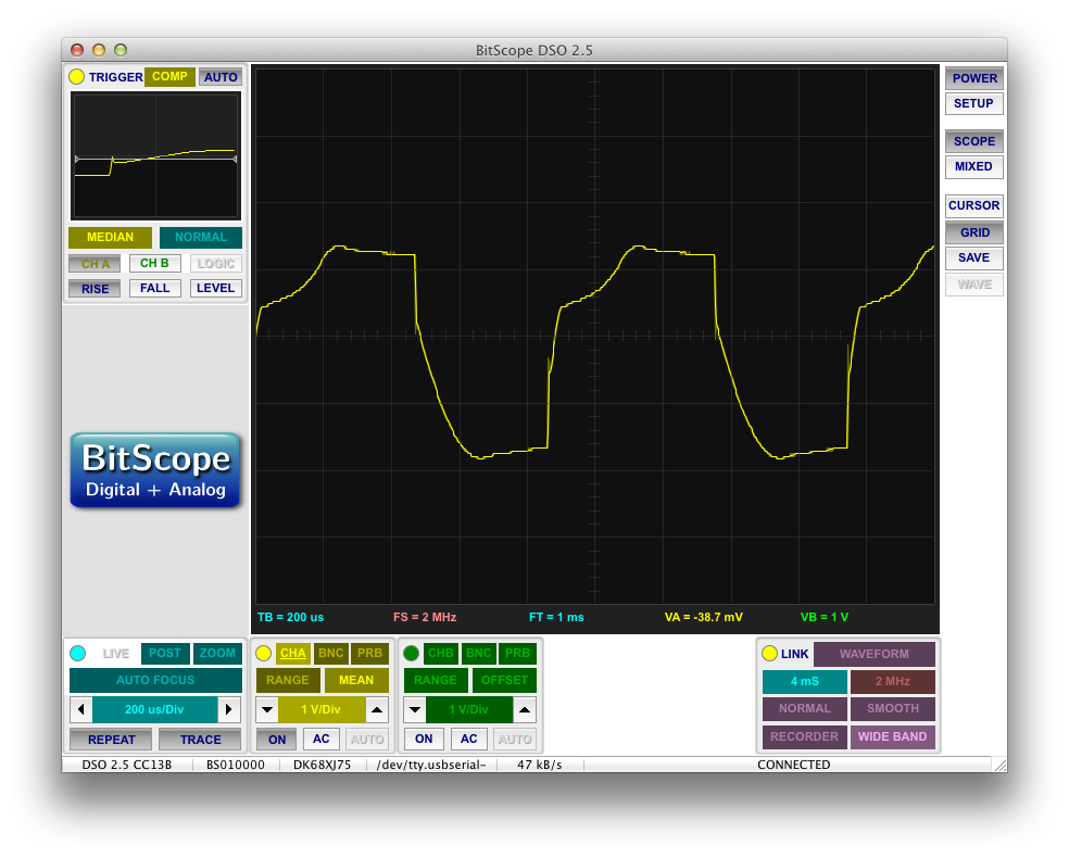
At least I think this is the problem. When I try driving my EL panel with my TRIAC, this is what I see:
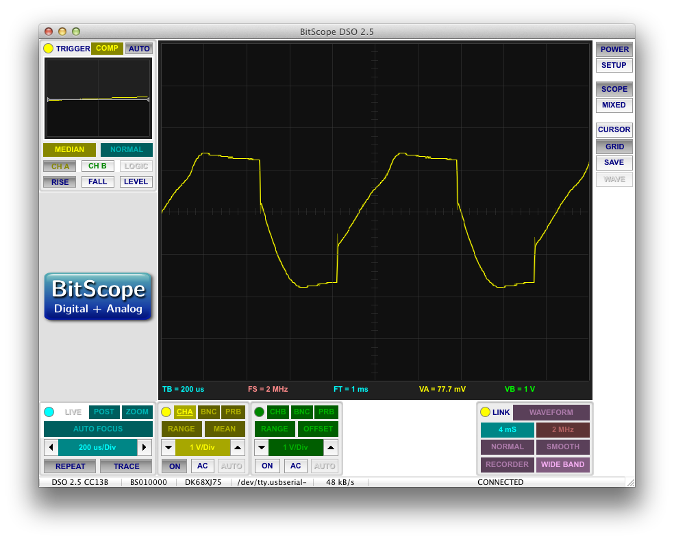
Adjusting the time delay on the TRIAC gives me a slightly warped version of the same waveform:
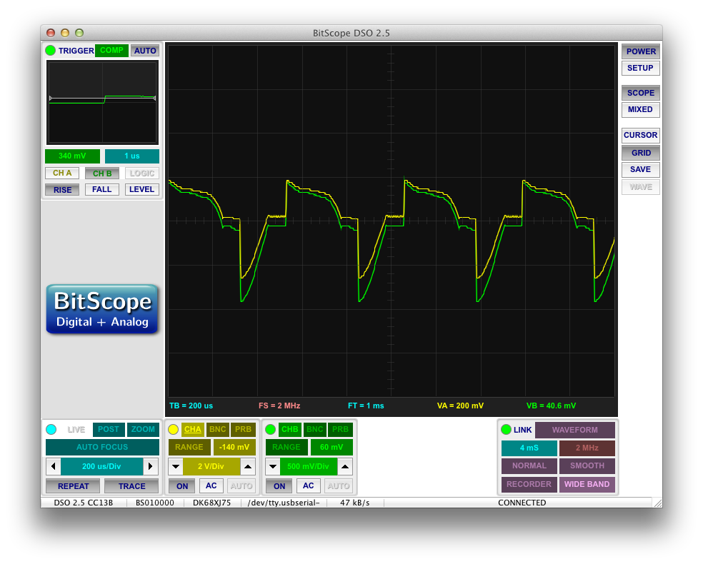
So it’s definitely not a typical TRIAC waveform. Although I can’t pinpoint exactly how this current-voltage disparity is contributing to the problem, I can demonstrate it. I reconfigured my circuit to drive a resistive load with a current-sense resistor between the TRIAC and ground. I measured the voltage across that resistor using the green trace:
As you can see, they’re synchronized. Now let’s look at the EL panel:
See what I mean? The current is leading the voltage by a ton. You get a huge spike of current right at the beginning of each half-cycle.
With the TRIAC, no matter what I do to dim it, I am delivering the same amount of power to the EL panel. So maybe TRIACs just aren’t made for dimming EL panels this way.
Crappy supply
The supply that I purchased for this experiment is probably a very simple blocking oscillator that is very poorly regulated (if you can say it’s regulated at all). It’s simply not the rock-steady 60Hz AC you get out of your wall that TRIAC dimmers are usually designed for. Playing around with the current draw in the middle of a cycle can have very negative impacts on the quality of the supply’s output.
For instance, I noticed even with the resistive load that changing the timing of the TRIAC actually slightly adjusted the frequency of the supply. I also noticed the shape of the supply’s output warp dramatically as I adjusted the TRIAC timer. That’s never a good sign.
ELECTROLUMINESCENCE
Before I tried all of this, I probably should have known that it wouldn’t work very well based on what I learned about EL panels in my previous research. What makes them light up is the rapid reversal of the potential across their leads. This causes the charges inside the panel to move around, and it’s this rapid motion that makes them light up.
Even if my TRIAC could produce the right kind of waveform, I don’t know that it would have worked very well because instead of going directly from positive to negative voltage, I would be stopping at zero for a moment each cycle.
Conclusion
So I guess I’ve failed yet again to dim an EL panel. It’s not a huge deal. I still got a great refresher of TRIAC dimmers which actually might come in handy in a future project I’ve got planned.
I do feel a little bit like Edison though: discovering 10,000 ways not to make a lightbulb.
Continue the story here.






Wow!
This is a great article! For a future project I read a bit about Triacs and how you modify the waveform to dim a load (in my case a heater device) but the texts left my slightly confused with the thought in mind “Well… maybe it comes all clear, when I eventually try it and blow it up” 😉
But now I’m confident do know what I’m doing when I’ll do it 😉
Thanks for that!
Regards TOM
PS: one half of that captcha is barely visible… and (for me being German?) I do not understand the spoken version
woo-hoo! I beat that captcha! Twice!
(at least I will have beaten that captcha, I you are able to read this second post! 😀 )
You’re the second person to complain about the captcha. I used an easier one before, but I found that some spambots were able to get through it. Maybe I’ll try a different one.
You could try cycle swallowing.
Your high voltage AC waveform has 1200 cycles per second. Mentally partition its waveform into “squads” where each squad is a sequence of 64 cycles.
Use a “magic synchronized high voltage AND gate” to output the first full and complete cycle in each squad, and to output nothing (ground) for the next 63 cycles
of the squad. That gives you a brightness level of (1/64), while at the same time presenting the EL wire with exactly the waveshape it expects.
If you output the first seven full and complete cycles of each squad, followed by nothing (ground) for the next 57 cycles, that gives you a brightness level of
(7/64). And so forth.
You could implement this with a pair of 6 bit digital counters and some glue logic. You’d use positive edge triggered clocking for the counters & logic, where the digital clock’s rising edge is aligned with the high voltage AC waveform’s positive-going zero crossing.
The “magic synchronized AND gate” is merely an opto isolated triac-driver WITH ZERO CROSSING TRIGGER. Like the MOC3063, made by many vendors and sold for $0.67 at Digikey. Check out its datasheet, it is just what you want.
Your digital logic says “Send the AC waveform to the EL wire beginning on the next cycle”. That logic signal drives the input (LED) end of the optoisolator. The zero crossing doodad inside the optoisolator then waits for the next zero crossing, and fires your existing triac. Voila, perfectly synchronized with the AC waveform. You get full and complete cycles of the AC waveform, from zero crossing to zero crossing.
Note to advanced readers: you may be able to achieve the same objective using fewer digital chips, if you jettison conventional counters and instead build a
6 bit Binary Rate Multiplier. See the TTL chip “SN7497” and/or the CMOS chip “CD4089” for more details. BRMs have the advantage of less flicker at medium and low brightness settings.
Dang! You spoiled it! I’m planning on trying exactly that, but I thought it would be worth it to write up my current approach before proceeding.
Since I’m still trying to make a sound-reactive t-shirt, I’ll be controlling the whole thing with a micro-controller anyway, so I can forgo all the glue logic and just do it in software. I’m not certain what kind of effect this will have on the power supply’s output though. I know that I’ll at least need to throw in some kind of dummy load along with the EL panel because the supply shuts down when you stop drawing power out of it.
I actually didn’t know about zero-crossing TRIAC triggers before. That’s awesome! That’s going to make things a lot easier.
Thanks for the tips!
Thanks for the writeup. I’m designing a variable-setting resistance heater for a certain type of kiln. I’ve been exploring TRIACs..rather than chopping the AC wave, I was going to do this but at 50/60Hz. 12.5% duty cycle would be one wave on, 7 off (or one half on, 3.5 waves off). And so on.
It expect it will buzz, but it’s quieter than the traditional mechanical relays turning on and off every minute. Best of luck!
Pingback: How not to dim EL panels, TRIACs! - Hack a Day
Pingback: Indagadores |Seguridad informatica |Seguridad en internet » ¿Cómo no para atenuar los paneles EL, triacs!
Pingback: Belgaum news | About Belgaum | Belgaum information | Belgaum district | Belgaum city | Belgaum Hotels | Belgaum People | Belgaum tourism | Belgaum entertainment | Belgaum students | Inside facebook | Hack | make use of | technical news | | How not to dim
Pingback: How not to dim EL panels, TRIACs!
Pingback: How not to dim EL panels, TRIACs! | Orange Claymore Red Slime
Pingback: How not to dim EL panels, TRIACs! « My Horizon Wireless
“What would you call a TRIAC with 2 pins?”
Were you ever able to borrow a Class-D amp from Bernie while under previous employ? Given all the steps you’ve taken thus far, would you have been able to garner any knowledge sooner?
Haha good times! Didn’t realize you were a reader.
I actually wasn’t able to borrow a Class-D, but I’ve got a new idea that will definitely work i.e. I blatantly copied it off a design I found online. Probably should have tried that first. The best engineer is a lazy one.
It’s good to hear from you.
A diac. Yes. They exist.
Inside joke.
Pingback: How Much Power Does an EL Panel Need? | ch00ftech Industries
On occasion. Something passed by my desk yesterday that reminded me of you and decided to see how you’ve been doing since you moved.
You have “the knack” and I want to see where it takes you.
Pingback: How TO dim EL wire: Current limiting the oscillator! - Hack a Day
Pingback: Sound Reactive EL Panel Dimmer (for real this time) | ch00ftech Industries
Magnificent website. Lots of useful info here. I’m sending it to several pals ans also sharing in delicious.
And naturally, thanks for your sweat!