I learned something valuable this week. Sometimes it’s best to “see how the other guys are doing it” before trying something yourself.
Introduction
For those of you just tuning in, almost three months ago, I attempted to build a dimming power supply for a large sheet of electroluminescent material. The tricky part is that EL materials need about 120V of alternating current to operate and dimming them involves changing the frequency of that current.
This project spawned the longest and most horrible post on this blog to date. Don’t get me wrong. The post has a lot of useful information for building a flyback boost converter from scratch, but it all gets mixed up in the number of post-publication edits I had to make as I discovered how wrong I was about everything. The main issue was with what I had assumed about my load.
The long story can be found here, but the short story is that I basically made the assumption that my EL panel looked like a 56k
![]()
load to my 120V power supply. Turns out that’s not the case. It was easy for me to make this mistake because I had never actually seen the panel lit up to full brightness before.
Realizing that my EL panel wasn’t a conventional load and behaved very differently at high voltages than at low voltages, I decided it might be a good idea to buy an off-the-shelf power supply to see how it performs. Measuring the electrical conditions of the panel when it’s being lit the “right way” would give me some hints as to what I was doing wrong.
How well are the other guys doing it?
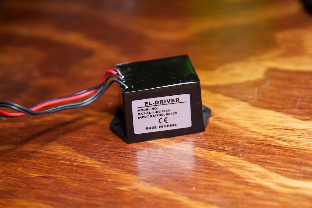
Looking around on Ebay, I found a cheap 12V EL panel power supply that is rated for A5 sized panels:
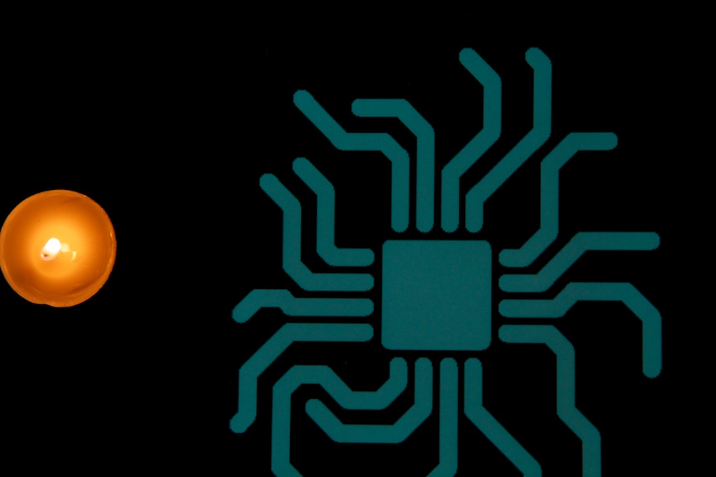
This little bad boy takes 12V in and does a pretty good job of lighting up my EL panel. Below, I have two images of my panel. The first is lit with my old power supply, and the second is with the off-the-shelf supply. The candle is included as brightness reference:
So you can clearly see that the second supply makes the panel much brighter. This probably has something to do with the fact that my power supply can’t maintain the 120V necessary to power the panel at full brightness, but it could also be a matter of differences in frequency (higher frequency is typically brighter).
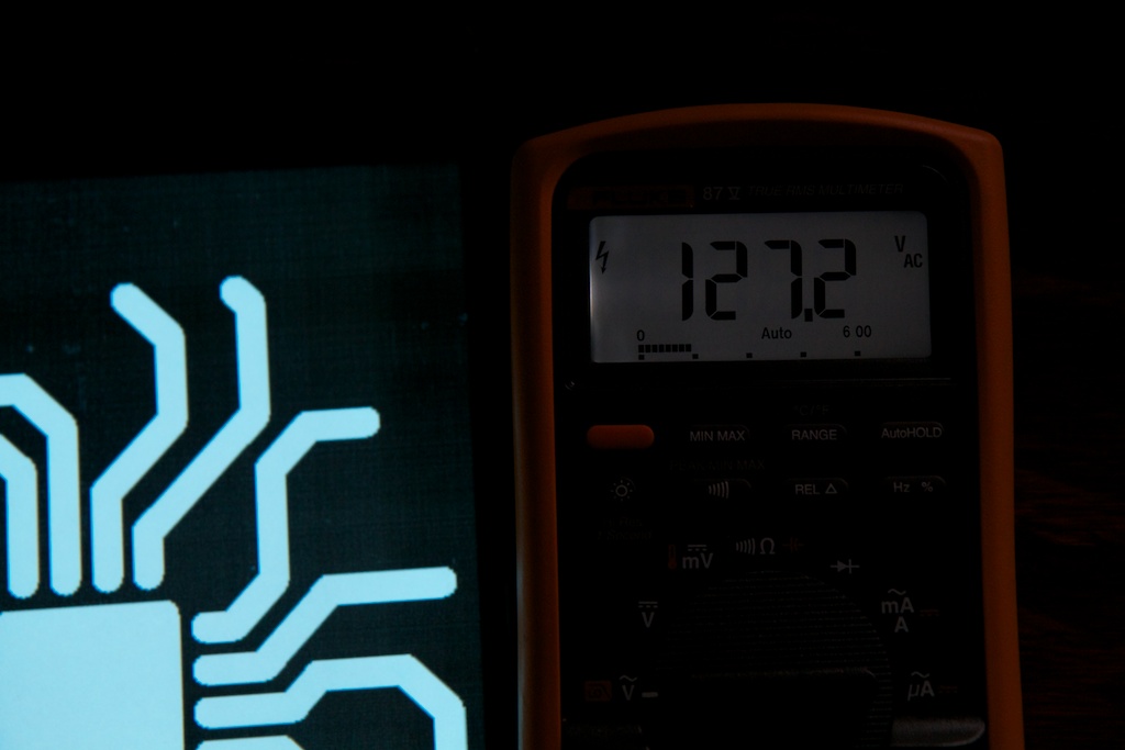
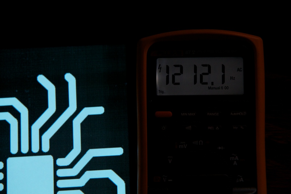
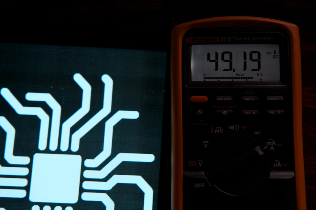
To measure exactly what this supply was delivering to the panel, I spliced up its output cable to let me do voltage and frequency measurements as well as in-series current measurements.
Here’s what I came up with:
So the voltage is 127V which is around the 120V I expected. The 1.2kHz requency is a little unexpectedly high though. The datasheet that I found for a similar EL panel said not to go over 1000Hz. Granted, that datasheet was not written for this EL panel, but either way the only danger of running at too high a frequency is a slight reduction in panel life. Not a huge deal.
What is immensely surprising about this test is the current draw from the EL panel. When I first started designing my power supply, I was making the assumption that my load looked like a 56K
![]()
resistor which at 120V would draw only 2.1mA, so I designed my power supply for a 5mA current draw. The panel is actually drawing 50mA or ten times that. 50mA is a substantial amount of current. Most bright LEDs can only take about 20mA, and that’s at maybe 2-3V. Here, I’m delivering 50mA at one hundred twenty volts.
Clearly my power supply was never going to work very well even if I did over-engineer it slightly for the load I thought I was dealing with.
Update:
I really need to start being more thorough with my investigations before I start blogging about them. I forgot to take into account reactive power, so while my output is apparently supplying 50mA at 120V, my input is only drawing 120mA at 12V. Details here.
So now what?
This does change a lot. Firstly, the flyback converter regulator chip that I used on my design has a maximum switch current of 1.6A which at 6V input is barely enough current to produce the 6 watts being drawn at my load at a reasonable duty cycle.
Even if my power supply could manage to maintain its 120V rail without sagging, my PFETs on the high side of my H-bridge are only rated for 35mA of current which is far under the 50mA the panel actually requires.
In short, this new information makes my previous design more or less worthless. Furthermore, I might have some difficulty finding more robust parts if I want to stick with the previous architecture in future designs.
I’m definitely not giving up now. Now that my conventional approach has been made much more difficult, I’m free to branch out into less conventional methods. I’ve got a few ideas bouncing around for how to make this whole thing work, and if one of them works, I might end up with a much better final product than I would have gotten with my original approach.
Still, it might have been nice to learn that my design wasn’t going to work before I started on it.
Continue the story here.



Pingback: Method #1,571 For Not Dimming An EL Panel: TRIAC | ch00ftech Industries
Pingback: Revisiting the EL Panel and the True Meaning of RMS | ch00ftech Industries
Pingback: Reactors to Full Power | ch00ftech Industries
Hey may i know the price of EL driver which you used? or the link from where i can buy it..i searched on e bay but couldn’t find it.
Here’s the one I bought:
http://www.ebay.com/itm/12V-electroluminescent-inverter-for-A5-size-EL-panel-sheet-back-light-strip-wire-/120850388247?ssPageName=ADME:L:OC:US:3160
Looks like around $14.
Pingback: Sound Reactive EL Panel Dimmer (for real this time) | ch00ftech Industries
my friend has purchase a el sign this has 10 letters in 2 rows at 5 inches high each letter.
the only wire comming out is a ribbon cable that has several wires and on with red. NO SCHMATIC,NO INSTRUCTION,NO POWER SUPPLY.
SO.
here is my studpid question. can i connect this sight directly to 120 vac
i noticed that the red wire jumpers, so i think this would be the common.
any help would be really appreciated.
thank you,
al
You can connect to 120VAC, but please be very careful.
How many wires are coming out of the panel? There is usually a single wire for each light-up section plus one common wire shared between them. Applying one side of your VAC to the common wire and the other side to one of the other lines should light up one section of your display.
There are plenty of panels and in power inverters for sale here
http://www.etsy.com/shop/lightkraft
wow so beautiful
I have EL night lights, which are meant to be plugged mains power (120v 60Hz). I happen to live outside the US, so my mains is actually 220v 50Hz.
The device itself consists of noting more than an EL panel and a plastic frame. The EL panel is connected directly to the mains power.
The EL panel size is approximately 4.5cm by 4.0cm (
I was wondering – Will the EL panel survive being connected to 220v? If 220v is too high, will connecting 2 panels in series allow me to power them with 220v without burning them?