I got EL wire to dim! And I made this:
Background
Ever since the travesty that I made back in May, I have been trying to find a good way to dim electroluminescent (EL) wire and EL materials in general. EL wire requires around 120V AC at about 1-2kHz to light up (you can read more about it here). My last good attempt at dimming EL involved building a 120V DC power supply and then switching the output to produce an AC square wave. This ended in disaster which I won’t bother to describe here.
A little while after that experiment, I decided that it might be a good idea to see how “the other guys” are doing it. I’ve since learned that it’s always a good idea to see how the other guys are doing it. As they say, the best engineer is a lazy one.
How Are The Other Guys Doing It?
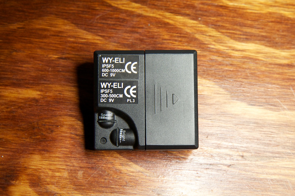
Looking around for dimming EL power supplies, all I came up with is this:
I hedged my bets and bought two: one from Ellumiglow and one from ebay. They turned out to be the exact same supply which leads me to believe that it’s the only supply out there that claims to dim. It runs off of a 9V battery and has two knobs and a button that changes its mode. One knob adjusts the rate of blinking when it’s in the blinking mode, and the other adjusts the general brightness of the output.
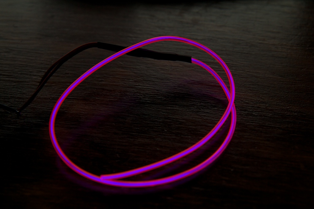
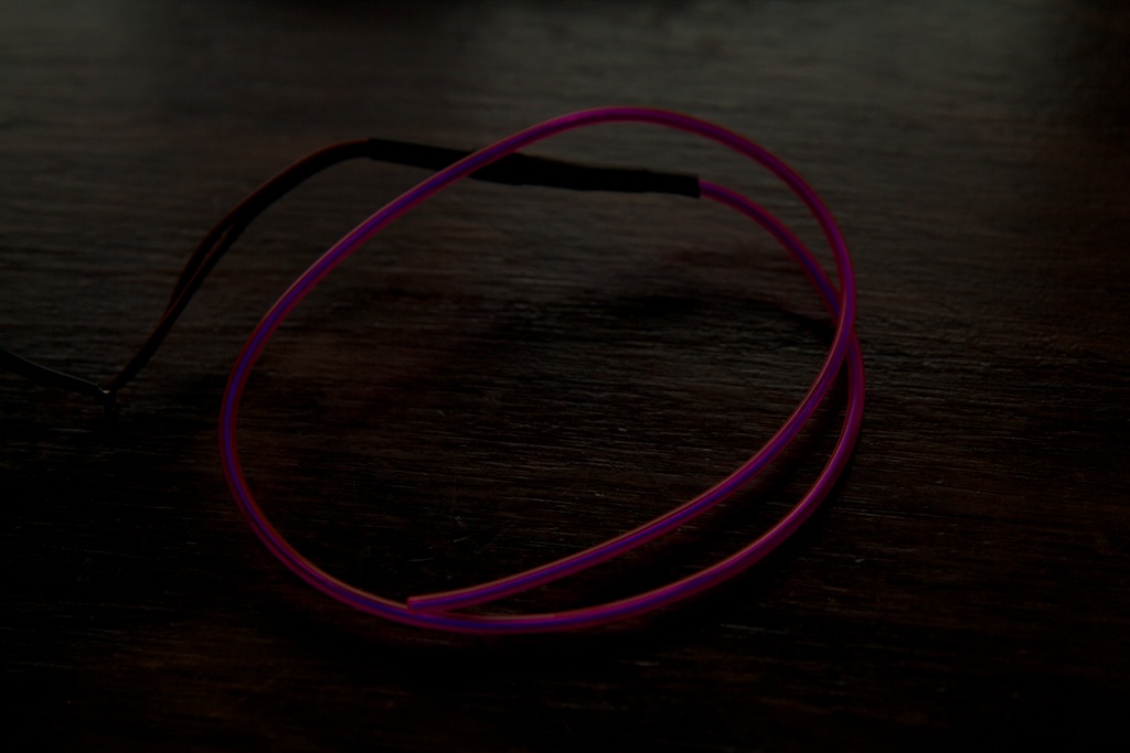
Of course, I could hardly wait to rip this thing apart to see how it worked, but before I did, I decided to rate its performance. I connected it to a good length of wire and took a picture with the knob in the brightest and dimmest positions.
 The supply had a surprisingly large range for brightness output with the dimmest setting identical to having the wire disconnected entirely. I then tried doing the same with a shorter piece of wire:
It might be hard to see in the images, but the wire was still partially illuminated even at the dimmest setting of the supply. Whatever the supply was doing, it couldn’t maintain its performance under a light load.
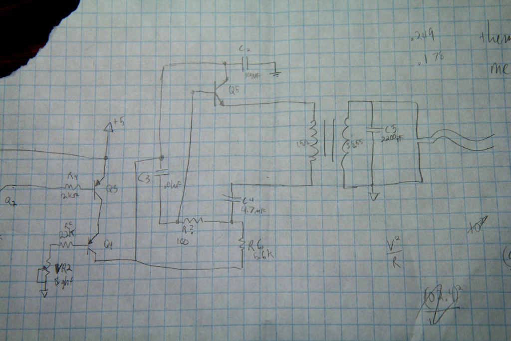
Taking the supply apart and doodling out the schematic, I produced this:
Note: I drew the transformer here incorrectly. The primary winding is a center-tapped coil like the transformers I’ve seen before. Unlike the other transformers, the bottom top half of the primary winding is tied to the ground VCC pin so that there are only 4 pins (instead of 5). Because of this, I forgot to draw the second half of the primary winding. Details here.
Although the right side of the schematic is a little messy, you might recognize it as the blocking oscillator that I have seen so many times before (and wrote this about). On the left side of the circuit, I found two PNP transistors. Q3 was connected to the output of a small micro controller and was presumably to control the blinking functions of the power supply. That leaves Q4.
Q4’s base was connected to the potentiometer labeled “Brightness”, so I could assume that this had something to do with the dimming functionality. It looked like Q4 was simply acting as a current limiter into the blocking oscillator. By changing the value of the brightness pot, the user is modifying the current flow out of the base of Q4 which in turn limits the current flow out of the collector of Q4 and to the rest of the circuit. Less current into the oscillator means less brightness out.
SO IT REALLY IS THAT SIMPLE
In my defense, I thought of such a solution before but dismissed it for my purposes (reacting to music) as I feared that adjusting the input current too rapidly would cause issues with the performance of the resonant supply. For example, what would happen if I oscillated the input current at a rate that neared the resonant frequency? Would it still work? How high of a frequency can it handle?
Another disadvantage is that this design requires your supply to crap out eventually to get to minimum brightness. With a small enough load, the resonant supply will likely still be able to perform at very low settings. This explains why the short piece of EL wire never went completely dark. For smaller dimming applications, it might be a good idea to use a smaller transformer that will “crap out” with a smaller load.
My Turn
Unlike the store-bought supply, I wanted to make something that had an electronically controlled brightness (no knob that needed to be turned). Rather than jumping straight into making a sound-reactive supply, I wanted to try something simpler where I could vary the brightness more gradually to avoid any of the issues mentioned above.
A friend of mine has developed a sleeping disorder that has been plaguing her for months. I thought it would be a nice gesture to make her a dreamcatcher to “help”. Rather than making a boring conventional dreamcatcher, I wanted hers to double as a night-light using EL wire webbing.
As far as the dimming aspect, I stole an idea straight out of the Apple playbook (don’t sue me!). If you ever look at an Apple notebook sleeping, you’ll notice that the power indicator LED slowly brightens and dims. This happens at a rate of approximately 12 times per minute. Apparently Apple did some research to determine that the breathing rate of the average sleeping person is approximately 12 times per minute and thought it appropriate that their laptops do the same.
So the goal was to build a dimming EL wire dream catcher that gradually pulses brighter and dimmer about 12 times per minute (.2 Hz).
Dream Catcher
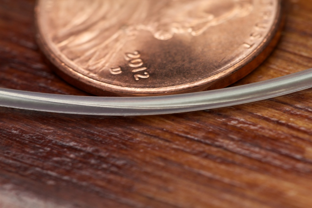
The dream catcher aspect of this project was very simple. I searched for the thinnest and most flexible EL wire available. I came up with this stuff from Ellumiglow. The wire only comes in blue-green, and it’s 1.4mm in diameter.
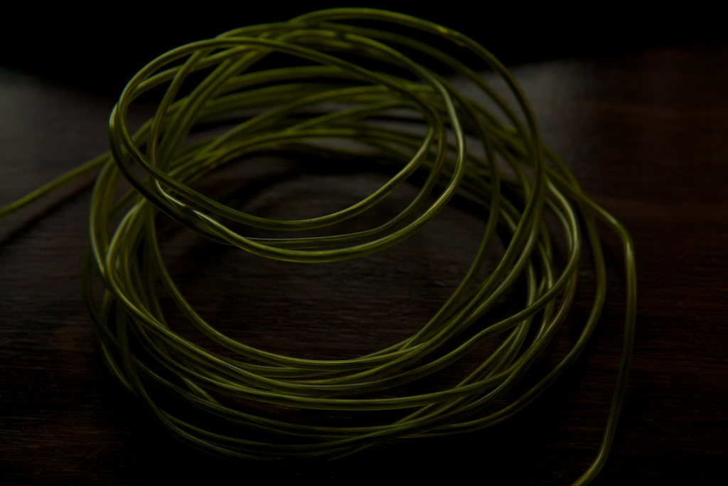
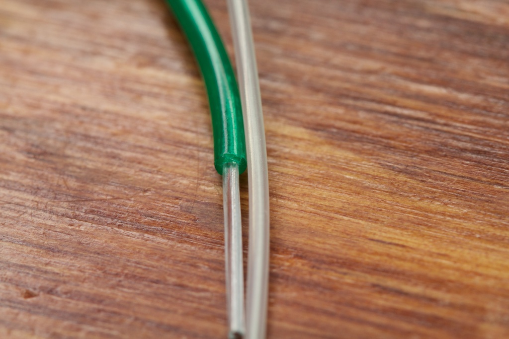
It’s pretty thin stuff. Unlike most EL wire, it has no second colored shell. This probably explains why it only comes in one color. Strangely, it looks like it’s slightly thicker than the core of normal EL wire:
Along with the wire, I purchased a simple make-your-own dreamcatcher kit from Amazon. The kit came with instructions and almost everything you need to make your very own dreamcatcher:
If you get one of these, be warned. Blue leather dust gets EVERYWHERE.
I assembled the kit once to determine approximately how much thread I needed so I knew how much EL wire to order. Once the EL wire came in, I removed the thread and added the wire instead:
The wire wasn’t nearly as flexible as the thread, so there are visible loops at the junctions. While this isn’t ideal, it still looks very cool in its own way.
If you’re only interested in making a light-up dream catcher, you can stop here. Wiring this thing up to any standard EL wire power supply will give you what you want. If you want to make it pulse though, keep reading.
Power Supply
So the goal here was to create an EL wire power supply that would slowly pulse the EL wire brighter and dimmer about 12 times per minute. Also, EL wire has a limited lifetime (it will “wear out” if you keep it lit for too many hours), so I wanted to build in some kind of automatic time-out that would turn the circuit off after some period of time.
I came up with this:
Resonant Driver
This part is probably the simplest, so I’ll talk about it first. This is the standard resonant EL wire driver supply I’ve talked about before. Terminals EL1 and EL2 connect directly to the EL wire. I got the transformer out of one of the many cheap EL drivers I’ve dissected.
Note: It’s come to my attention after shipping the dreamcatcher that it may not be operating at peak brightness. I never measured the output voltage, but it’s possible that it will never reach the typical 120V value. The value for R2 was taken from an EL supply with a larger transformer and was likely tuned for that transformer. For smaller transformers, a value of 1k should be used. I’m not too worried because this is a night light, not a spot light, and if anything, it will prolong the life of the wire.
Dimmer
The purpose of this section is to fluctuate the current passing through Q6 going to the EL supply. Q6 is a PNP transistor. I’m sure a number of PNP transistors would work, but I chose the MMSS8550 because it is the same model I found in the store-bought supplies (I’m shameless, I know).
The 555 timer is configured as an astable oscillator with a frequency of about .2-ish Hz. Due to the large tolerance of the capacitor I used, I ended up having to tweak R4 and R17 a bit to get the performance I wanted. R4 is smaller than R17 so that the duty cycle of the output will be closer to 50%.
Now I’m doing something a little tricky with the 555 timer. This 555 timer keeps time by charging and discharging C5. It will charge C5 to about 2/3 of the rail voltage and then discharge it to about 1/3 of rail voltage. If you were to look at the voltage across C5 over time, it would look something like a triangle wave (though the function is exponential, it looks linear over this range).
U1 simply buffers this triangle wave and passes it to the base of Q6. As the triangle wave ramps up, the voltage drop across the emitter and base of Q6 and across R3 will become smaller and less current will flow into the resonant supply. This will dim the EL panel. As the voltage ramps down, the opposite happens and the panel becomes brighter.
The output voltage will never get high enough to shut off Q6 entirely, and the output will not be the sinusoidal output that you are used to seeing on MacBooks. This was by far the simplest solution though, and it’s good enough for a proof-of-concept.
Time Out
Looking at this section of the schematic, you’ll note that the DC barrel jack J1 is not connected directly to +5V (note that R10 is “DNS” or “Do Not Stuff” meaning that it should only be installed for debugging purposes and should be removed before “production”). Instead, the current is routed to +5V through Q7 which controls the “on” state of the circuit.
The rest of the parts here make up a simple flip-flop.
When the device is first plugged in, nothing happens. When the user temporarily closes SW1, current flows from the DC jack through the base of Q4 and to ground. Q4’s collector pulls current out of the base of Q7, and this turns Q7 (and the rest of the circuit) on. Even after SW1 is released, Q7 will provide current to Q4 and keep itself going.
U3 is a binary counter that is taking the output of the 555 timer as an input. Every time the 555 timer oscillates, it adds one to the binary output of U3’s pins (specifically on the high-to-low transition). This turns U3 into a frequency divider. Every binary place holder represents a division by two of the frequency. For example, if the input to U3 is 100Hz, the output of Q0 is 50 Hz and the output of Q1 is 25 Hz.
By the time you get to Q9, you’re looking at a division by 2048. If the input is about .2 Hz, the output of Q9 will be 0.00009765625 Hz. This means that while the input oscillates once every 5 seconds, Q9 will oscillate every 10240 seconds or once every 2.8 hours.
The output Q9 will never make it to a full oscillation though. As soon as it goes high (after 1.4 hours), it will turn on Q3 which will then turn off Q4 and Q7 in turn. In this way, it acts as a simple kill switch timer that prevents the device from running needlessly all night.
Because 1.4 hours is a long time to wait, I added some DNS resistors to other pins which I could temporarily stuff in lieu of R11 to make the shut off occur after a number of seconds.
As another note, Q3 used to be a normal NPN BJT, but I had to switch to a FET because it turns out that U3 doesn’t do a very good job of holding its outputs low. With an NPN, a small amount of current would leak through its base and turn the circuit off unexpectedly.
PCB
The PCB etch process came out extremely clean this time. Recently, I’ve decided to ditch the old toner-transfer method for the photo-etching method (I’ll be writing up a how-to at some point). This time around, I decided to do it all in a nearly pitch-black room to preserve the photosensitive resist material. Given how well it all turned out, I think I’ll be doing that again in the future.
After the etch process was done, however, it seems like I messed up everything.
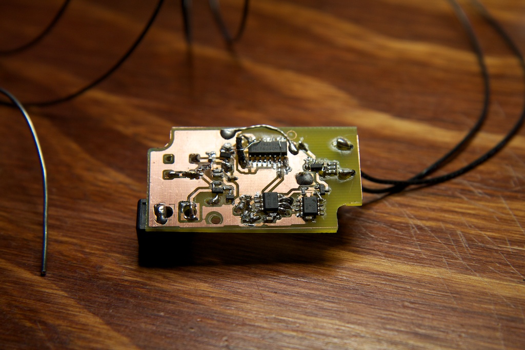
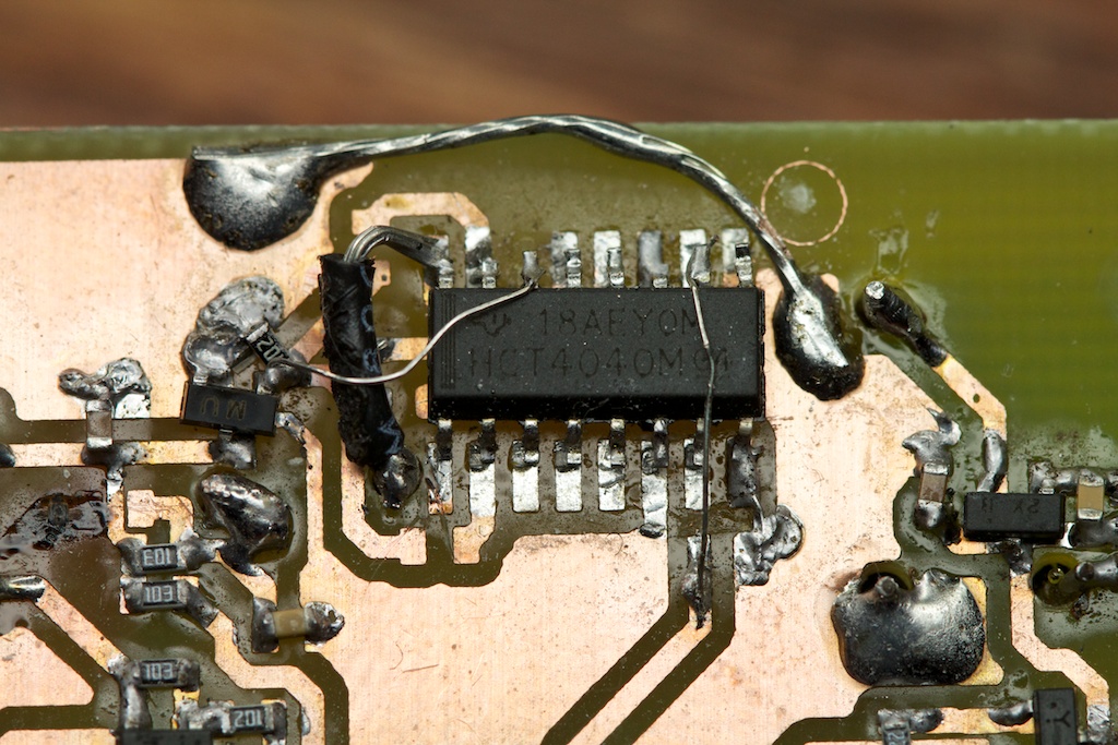
I had forgotten while ordering parts that I broke my 1/32″ drill bit a few weeks ago, so I had to drill all of my holes with a 1/16″ bit which completely destroyed all the copper pads for those holes.
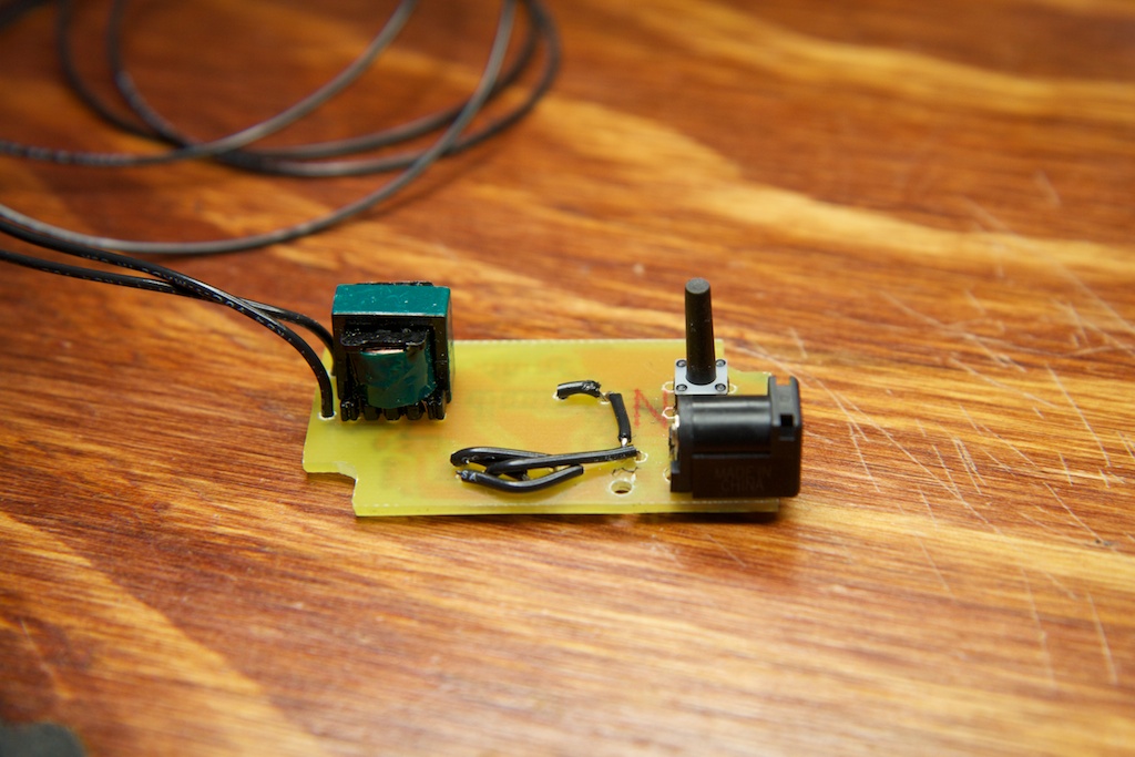
Also, in addition to leaving out a few minor traces, I completely messed up the foot print for U3, the binary counter. Luckily, I only needed to connect to a few of the pins, so I managed to improvise with some air wires:
I will be coating this thing with hot glue before I mail it out…
Once installed in an enclosure though, the whole thing doesn’t look too bad:
Not…too bad…
Performance
All things considered, I am extremely pleased with the result. The dream catcher pulsates in a soothing and somewhat creepy manner. See for yourself!
Also, the time-out kill switch works exactly as expected. A quick tap of the power button turns it on, and it glows softly for over an hour before shutting itself off.
Conclusion
I’m really excited that I finally got EL wire to dim. I’m also kind of glad that things turned out like they did. Though I definitely took the scenic route to a solution, I learned a lot along the way.
Seeing how simple it is to dim EL wire, I can see future applications of this technique that include very small dimmer supplies and even possibly multiple dimmers per circuit.
Regardless, it remains to be seen if this method can be used to dim EL wire at the frequencies required to keep up with audio input without interfering with the operation of the resonant supply.
Continue the story here.
Project files can be found here: Dreamcatcher package v1.0






Pingback: Reactors to Full Power | ch00ftech Industries
Pingback: Dimming an EL panel is harder than it looks | ch00ftech Industries
Please print the Visubal Basic commands for this thank you. I think you forogeotten them to print.
What are you talking about?
Pingback: How TO dim EL wire: Current limiting the oscillator! - Hack a Day
Pingback: Belgaum news | About Belgaum | Belgaum information | Belgaum district | Belgaum city | Belgaum Hotels | Belgaum People | Belgaum tourism | Belgaum entertainment | Belgaum students | Inside facebook | Hack | make use of | technical news | | How TO dim EL w
If you made this into a kit to purchase, even if you just sold the pulse box, I would buy it in an instant!
Thanks for taking the time to share this.
I like the way you attack things too.
Rombauer
Good job man! And thanks for taking the time to document it well.
From the video it looks really good in my opinion.
That is awesome man. That. Is. Freaking. Awesome. Man! I’ve been looking for something like this to make an awesome TRON costume (or Daft Punk) . I didn’t want just full brightness nor did I want to control the dimming on my own. Great show!
Pingback: Strongerer Glasses (with digital EL sequencer) | ch00ftech Industries
Pingback: Sound Reactive EL Panel Dimmer (pretty much done) | ch00ftech Industries
Do you know how to hook this up so it would be an alarm clock, like a sunrise clock, gradually getting brighter, rather than blinking?
Wouldn’t be too difficult. Firstly, remember that EL wire doesn’t get too bright, so if you’re planning on using it alone to wake you up, you will need to be a very light sleeper 🙂
If you want it to light up gradually, say over the course of a few minutes, you simply need to work out the proper RC time constant for the 555 timer. In this case, the timer will be configured in a “one-shot” or “monostable” mode. See page 6 of this data sheet. In this mode, the capacitor voltage will rise once and then fall to zero. You can use the plot on page 7 to help you determine your desired RC time constant. If you need more than 100 seconds of ramp time, you will just have to continue the plot off the edge and extrapolate the right number.
If you want the EL wire to stay bright at the end of the ramp-up period instead of shutting down, you’ll have to work out some logic with the output pin.
Very well done. Do you think that would be possible to use your solution to control el wire (or panel) brightness by a microcontroller? I confess that I did not fully understand your explanation due to my rather sloppy knowledge of analog electronic.
You absolutely could! You just need a micro-controller with an analog output to replace the microphone pre-amp stage.
I’m also an analog newb thinking about controlling EL with a Microcontroller (FEZ Panda II).
Would I connect my analog out straight to the base of Q6, or should I leave U1A in the circuit too?
Thanks for the write-up!!!
Assuming your analog out is reasonably powerful, you don’t need U1A to buffer it, but make sure you don’t forget R3. Q6 is current controlled, and R3 will change that voltage signal to a current signal.
Wow. While the analog stuff went right over my head, this helps me out quite a bit. Thanks for posting this!
If you have a microcontroller, you could also (maybe) use a digital potentiometer. There may be some frequency component, and you’ll (usually–model dependant) need to keep the voltage between its Vcc and ground, however.
Hi! You nailed it! congrats!…Now, can you connect a potentiometer to control the EL Wire Brightness? I have done it before with LEDs but I have never worked with EL Wire. Also, i’ll connect the EL Wire to a standart USB port which resistors do I need? or the 250 KOhms Resistance on the potentiometer will be enough? (A linear Potentiometer or a Single Turn?
If you look at the original power supply I borrowed my design from, they’re actually using a potentiometer. A 250k might be too much though. If you replace R3 with a potentimeter (or rather a rheostat or adjustable resistor) connecting the base of Q6 to ground, you should have an adjustable brightness. The smaller that resistance, the more current through Q6 and the brighter the wire. I’m not sure on linear vs. log pot, but I think linear will give you the best results.
Also, the whole circuit draws a fairly small amount of current, so USB should work fine.
Great post! I’m doing El project my own and trying to dim my El wire. This really helps me out.
Hi. What is the simplest way to fade in on power on and fade out on power off?
That should be pretty easy!
All you need to do is place your power switch and a low-pass filter before U1A. As the capacitor of this filter charges up, U1A will pass a rising voltage to the resonant driver and will slowly brighten the EL wire. The opposite will happen when you switch it off.
I didn’t get a thing from your project because I’m not an electronic person!
My question is:
Is a simple LED dimmer capable to dim el wire?
If yes, where i can i put it?
After the 12V supply and before this black box that came with the el wire, or after the black box and before the el wire itself?
I just need to reduce the brightness of the light in the car. It is disturbing me at night!
If you have any suggestions for any kind of dimmer that it would do what i need, please advise me what and where can i buy it.
Please reply.
Sorry for the disturb!