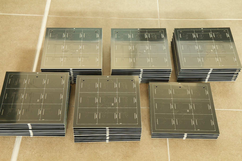
So I got the populated QR clock PCBs in:
And they look fantastic!
Objective
As you probably already know, I recently held a fundraiser to help bring my new and improved QR clock to market. The fundraising goal was 50 preorders, and although I only got 45 within the allotted time, I decided to proceed anyway figuring I’d sell the remainder after the fundraiser was over.
The original prototype took about an hour and a half to assemble, and since I don’t feel like quitting my day job to take up a career in burning my fingers, I decided it might be a good idea to look at some other options for assembly.
This post outlines my experiences of ordering PCBs pre-assembled. I decided to go into a lot of detail with this post because while the ordering process was fairly straight forward, there were some slightly confusing parts to it, and if there’s one thing you don’t want to be when you’re dropping a few hundred/thousand dollars on PCBs, it’s unsure. I figure this will be a rich resource for anyone planning on placing a similar order.
For anyone else, it’ll be pretty boring, so sorry about that.
As a caveat, I am not writing this at the time of my original order, so there’s a chance I left some details out as I didn’t feel like ordering another 50-some PCBs just for the sake of getting a few screenshots and forgotten details of the process.
To LED or not to LED
The clocks are a single PCB with a bunch of through hole LED matrix modules on the front and a bunch of surface mount components on the back. Originally, I was planning to have the entire clock assembled by a third party, but when I realized how long the lead time was on the LED modules, I thought it might not be a good idea to do it myself. Otherwise, I’d have to stack the lead time for the LED modules onto the lead time for the PCBs.
Besides, considering how important aesthetics are for this design, I thought it might be prudent to handle that myself. I was concerned that a 3rd party might make all the appropriate electrical connections but solder the displays unevenly which would severely lower the value of the clock.
When assembling the prototype, soldering the LED modules and ambient light sensor only took about 10 minutes. I can probably cut that down even more if I develop some kind of system. That means that all the clocks might take me around 8-10 hours or a busy Saturday.
So maybe the title to this post isn’t 100% accurate, but by following a similar process, similar devices could be made without any soldering.
Quoting
Starting out, I knew I had 45 guaranteed sales. I’ll go into specifics in a later article, but suffice it to say, once you cover setup fees additional units aren’t that expensive. I figured it would be a good idea to order some extras (since they weren’t that much extra cost) and sell them at a later time.
So 55 clocks.
I ordered the original PCBs from Myro. They’re a quality PCB manufacturer, and they also offer a PCB assembly option. Their website isn’t the greatest though, so it took me a few tries to place my order. I often found myself getting trapped in holes and having to re-enter the URL and start over.
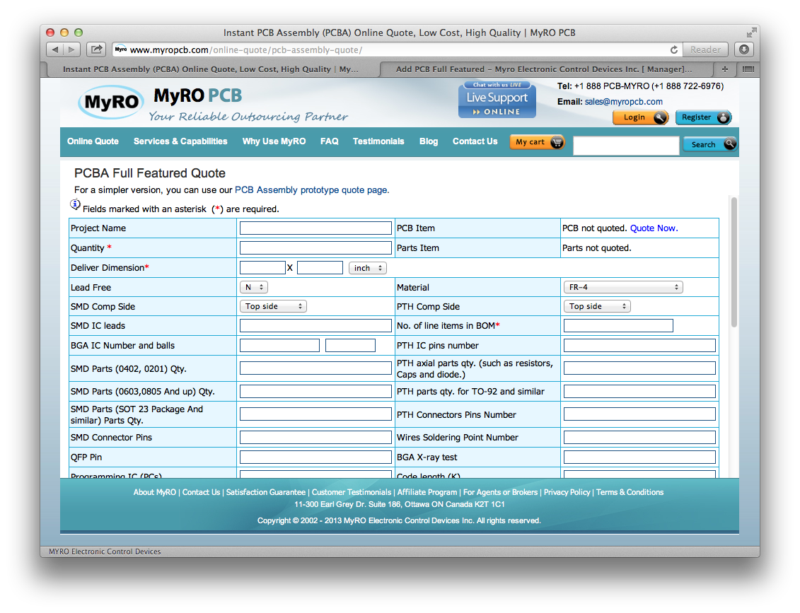
I started out by clicking the PCB Assembly link on the home page. This brought me to a window where they ask to fill in a bunch of details on the board to help them produce a quote.
They ask for a lot of numbers such as number of SMD parts, number of Through Hole connectors, etc. The bottom line is that this information doesn’t have to be 100% accurate or 100% filled in, but it will help them give you your quote faster and more accurately. They reserve the right to charge you more after inspecting your project files if assembly is significantly more expensive than what you specified on this form.
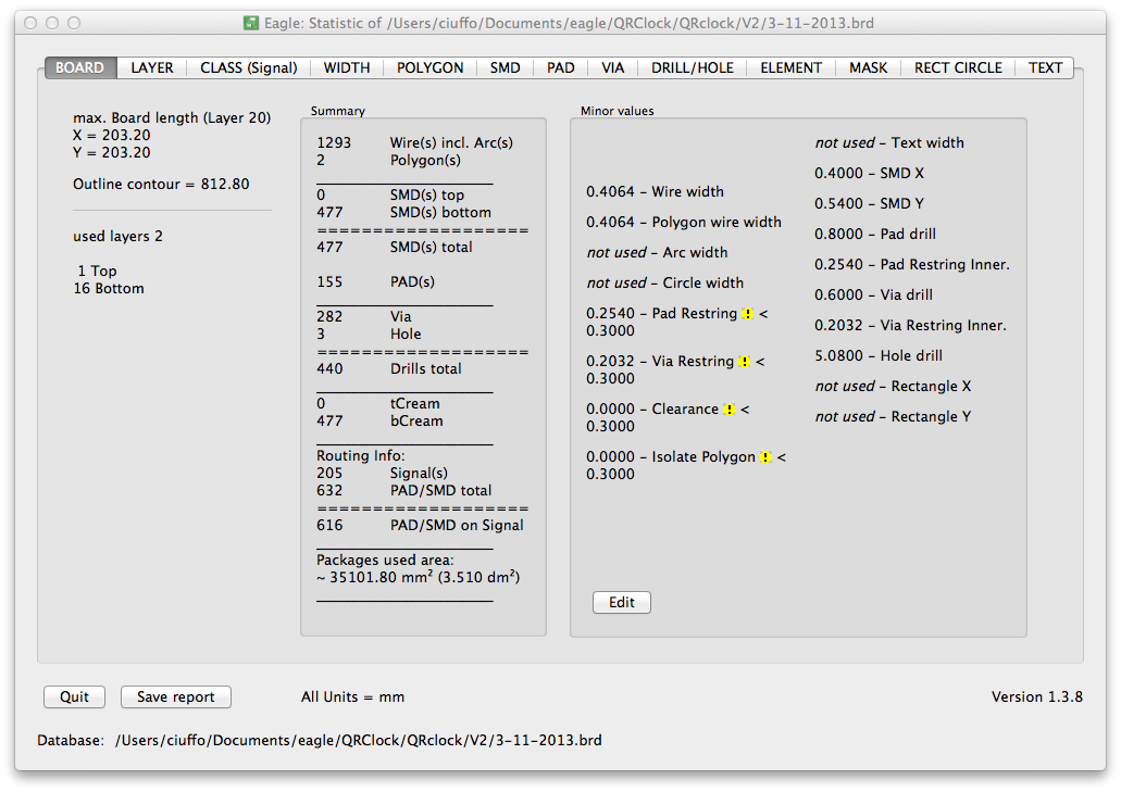
Running the “statistic-brd” ULP inside Eagle’s PCB editor will bring up a window that can help you fill out some of these:
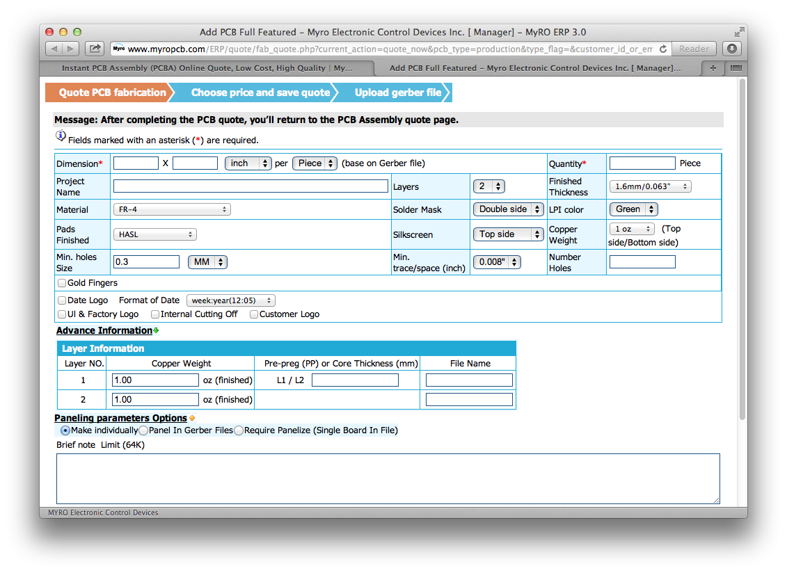
Now this quote is only for the process of assembling the PCB (soldering on components). This doesn’t include the parts to be soldered or the actual PCBs themselves. To add a PCB to the order, I clicked the “Quote Now” button in the top right of the assembly order window.
This brought me to a familiar window:
Which I had used before when ordering my prototype PCBs. Once I finished filling out this page, I clicked the “Quote Now” button which brought me to a page reviewing the information I input and allowing me to select a lead time. In general, the longer the lead time, the cheaper the process, though the savings have to bottom out at some point or they’d be giving you stuff for free. Because I was in no particular hurry to get these boards made (since I was waiting for the LED modules anyway), I figured that I would select the longest lead time possible that still provided me a cost savings.
They provide radio buttons for lead times up to 10 days, but I found that the cost savings leveled out at 12 days which I input into the “Other Lead Time” box. After clicking “Save Quote”, I was brought back to the assembly page.
Before finishing up the assembly quote, I made sure to select the check box “Partial or all parts to be supplied by Myro”. This is important as for some reason, you cannot modify this selection later. Myro has the capability to place part orders for you from Digikey. You just have to pay for them.
Now this whole quoting business is kind of strange. Myro treats the printing of the PCBs and the assembly of the parts to be two totally separate things. Each asks for a quantity. Presumably, you can order more PCBs than you assemble, but I’m guessing they’d throw some kind of error if you ordered more assemblies than PCBs.
It’s especially weird because in the quote review page, they show your “Qty.” as being the sum of your PCBs and assemblies as if they’re two different things. Suddenly, I found myself ordering 110 of something.
With all of the assembly information input, I clicked “Save Quote” where I was brought to another page where I could select lead time. This lead time was for the assembly process though and was to be added to my PCB printing lead time to produce the total production time. Clicking “Save Quote” again brought me to a page where I could review my quotes and choose which to order.
Design Files
In order to start ordering, I needed to add some design files (y’know, because it’s hard to print a PCB when you’re only told how big it is). Clicking on my quote brought me to a review page. My quote was split into two parts, 1(fab) and 2(assemble). The titles are pretty self explanatory.
The window for 1(fab) brought me to a page where I could upload my design files. Just like most other fab houses, Myro accepts their PCB design files as Gerber files in a .zip folder.
I laid out my PCB just like I always do, but this time making sure that my part labels were extremely orderly. When I’m assembling a PCB myself, I can always look at my Eagle file if I’m unsure where to place a part, but Myro won’t have that luxury. Some fab houses require a “pick and place” file to tell them where to put parts, but fortunately Myro only needs good labels. There’s a  100-200, I could have gotten that trimmed down, but again, considering I was waiting on the LEDs anyway, it was a great deal.
I have to say that ordering these PCBs was one of the most stressful things I’ve done in recent history. PCBs are pricey, and it isn’t easy to give $2k to someone in China and hope that they don’t mess anything up.
But considering it saved me…I dunno…about 85 hours of work, I’d have to say that it’s definitely worth it!
Stay tuned for more updates on the QR clock’s production.


Interesting post – I find it fascinating to follow your experiences with things like this, and appreciate the level of detail you include in your post.
If/when I’m ever in a position where I want to get multiple PCBs made and assembled, I know where to go for ideas 😉
Hi you may for same price make it assembled in america (canada)
and mormally i have 7 day leadtime…
we also able to supply blank pcb whit near same price as myro to
you may try price qoute here
http://www.alphatronique.com/?page_id=150
Best regard
Thanks for the tip!
I’ll consider you for my future projects.
Hi just think about that
you may try past in hole for the led ,bottom was assembler normally
then on top stencil put past on led hole ,then put led and reflow ..
surface tnesion will hold part in place and led will
solderd straig since gravity will hold it
that may need some try for got right hole to pin ration but normally it work good
it amasing how mutch past may go back into hole even if pin push it out 😉
Best regard
This was a great post! The details and specifics are amazing. Great to read, thanks for posting!
Ordering circuit boards in bulk for a project must be a rush – a bit of risk and excitement! This guide is so useful for people looking to upgrade from prototyping to small run manufacturing PCBs.
Pingback: PCB advice and fabrication | Electronics and Education
Pingback: Vendor Bender | ch00ftech Industries
Pingback: Page not found | ch00ftech Industries