So, I finally figured out what the deal was with my accelerometer needing to be asked twice what the value was.
As it turns out, I wasn’t actually giving the chip time to reply. I thought the micro would automatically handle receiving the data value, so I all I had to do was send the ACK at the end. In fact, the command that sends the ACK actually tells the micro controller to wait until the entire data byte has been transmitted, and then transmits the ACK.
So, when I was storing the value before sending the ACK, I was storing the value that I originally had in the register (the address of the accelerometer chip) and then waiting for the data and finally sending the ACK. Now, I’ve changed it so that it waits for the data and sends the ACK before storing the data value in the register.
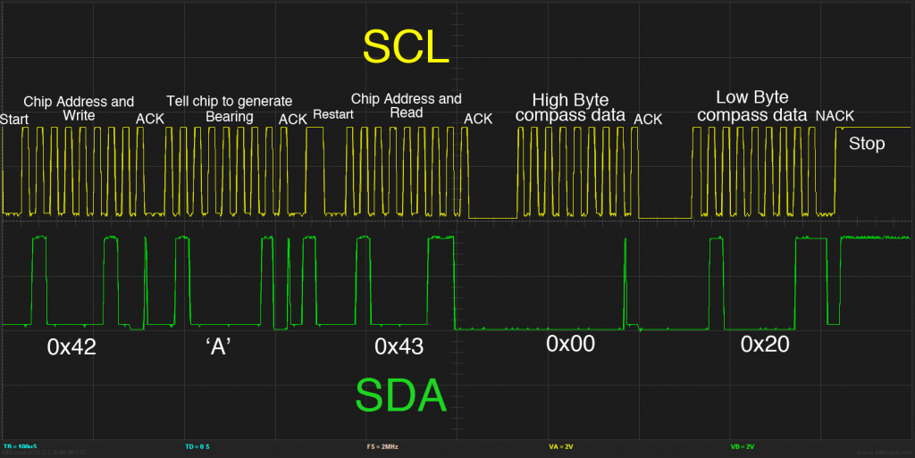
How did I figure all of this out? With an O-scope! I simply modified my code so that it would give me a voltage spike on one of the output pins while it was reading the data from the register. What I noticed was that it was spiking before it was supposed to. Here’s an example of what I mean:
Here’s a plot of the two I2C lines while talking to the compass chip. The spike I was noticing was right after the “Chip Address and Read” segment, but before the “High Byte” that means that I never gave it time to actually read back the data!
Oh, what’s that? You didn’t know that I got the compass working too? Did you even read the title to this post?
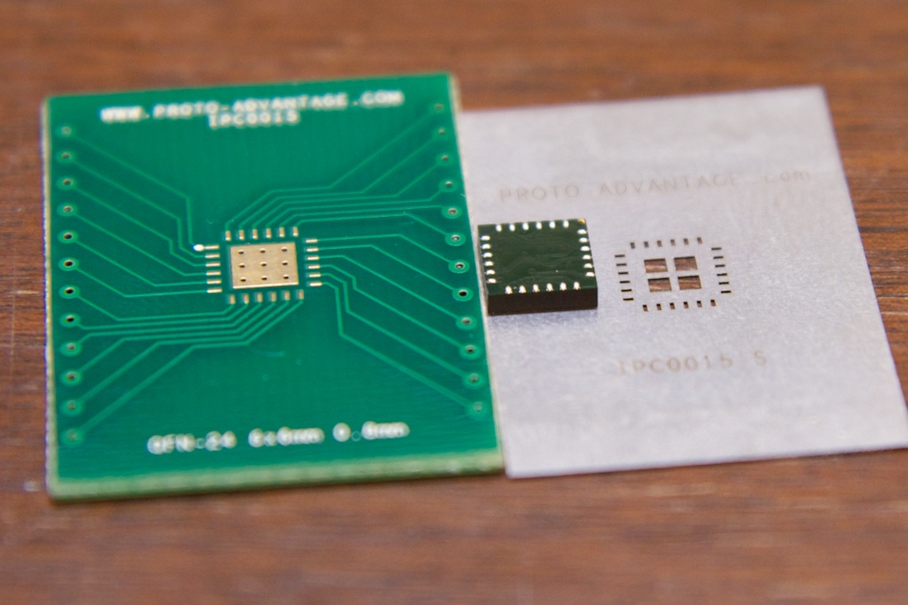
Yep, it’s working. Doing the reflow soldering was a little tricky because the compass doesn’t really have QFN-24 footprint (I don’t think it’s a standardized footprint). The main difference is that the compass doesn’t have the huge ground plate that QFN-24 provides. As seen here:

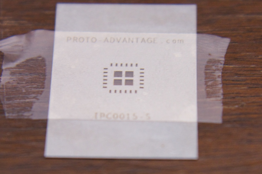
My solution was to simply cover the stencil with tape:

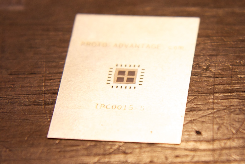
and carefully cut around the center holes:

Ta Da!
So, the compass works! It did need a little calibration. There’s a routine that it can run wherein you’re supposed to slowly spin it around while it collects data. When you tell the routine to stop (it recommends anywhere from 6 seconds to 3 minutes long), it does some math and figures out what magnetic fields are local to it (inherent in the circuit it’s on) and what magnetic fields are due to the Earth. I didn’t know I was going to need a calibration function, so I’ll have to work that into the final design somehow.
The compass reports bearing as 1/10 a degree per digit. Here, you can see it displaying the top 4 bits of the compass bearing. Notice how dramatically it changes as the compass passes magnetic north.

