When I was at the rock gym last week, one of the staff members had some gloves with blinking LEDs in the finger tips and was dancing around like an idiot. A friend of mine was jealous and said in passing “you should invent something for me to swing around so I can go to a rave.”

So the goal was to make something cool (cooler than just generic blinking LEDs) that one could swing around during a rave.
Here are my design requirements:
- Cooler than blinking LEDs
- A nice user-friendly polished finish
- Made with stuff that I have lying around my apartment (time constraint)
I settled on making a Persistence of Vision toy. Persistence of vision is what allows these clocks to work:
Basically, they operate on the principle that your eyes react very slowly to changing inputs. If you have a row of LEDs moving very quickly, their light will hit different parts of your retina as they move. If you move fast enough, you will still be able to see the light coming from their first position as they move into their final position. This lets you “paint” images or text in the air.
To make a steady image, you need to map the LED blinking to a specific location in space. Presumably, the clock above has some kind of position encoder for the LED wand that flicks back and forth.
I didn’t want to go too crazy with my design, so I figured that I would just have the LEDs blink at their own pace and just make sure that the patterns are simple enough to be seen with a single pass.
I had some red LED bar graph displays lying around and an old ATMega48A. The schematic is pretty simple. Each LED is connected to a data pin of the ATMega in series with a 100 ohm resistor making sure that the micro-controller pins were sinking instead of sourcing the current (most micros can sink more than they source). Because the voltage drop across red LEDs is typically about 2v, this gives you a 1v drop across your 100 ohm resistor or about 10mA of current.
Concerning the current draw on the pins, the datasheet had this to say:
- Although each I/O port can sink more than the test conditions (20mA at VCC = 5V, 10mA at VCC = 3V) under steady stateconditions (non-transient), the following must be observed:
ATmega48/88/168:
1] The sum of all IOL, for ports C0 – C5, ADC7, ADC6 should not exceed 100mA.
2] The sum of all IOL, for ports B0 – B5, D5 – D7, XTAL1, XTAL2 should not exceed 100mA.
3] The sum of all IOL, for ports D0 – D4, RESET should not exceed 100mA.
I’m probably okay here. 8 pins (per port) with 10mA each is still under 100mA.
Here’s my schematic:
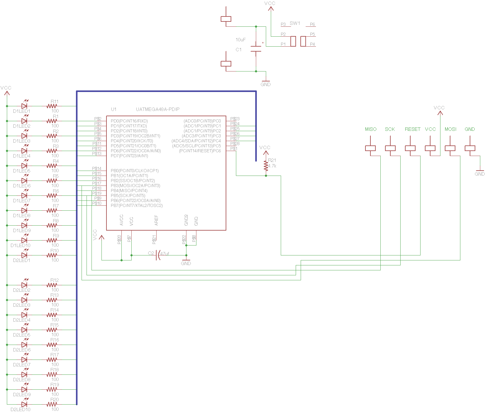
Though it’s really not much to look at because the bus makes it hard to determine LED mappings. This is actually kind of irrelevant because the LEDs can be mapped in whatever way is convenient when laying out the PCB itself. Here’s my PCB:
I actually set out to etch this PCB (note how it’s mostly one-layer), but I ran into some problems. I’ve had this bottle of Radio Shack brand PCB etchant that totally sucks and has ruined a number of boards. That’s just as well, because I realized after the fact that I made a few mistakes. I fixed them on the schematic, but didn’t bother on the PCB (notice the airwires). I wasted about 2 hours trying to get this to work and eventually gave up and just used perf-board instead (I actually had to cut some old components off an old circuit because I was out of fresh board).
I didn’t get any pics of the assembly process, but you can find a bunch of info on un-clad perf-board prototyping online if you just Google it. The only new thing is that I decided to remove the power switch. Because the batteries will be easily accessible, it’s reasonable to just have the user take one out when he/she doesn’t want to use it (after all, it’s for a rave and glow sticks don’t have power switches).
The next major (and really only) challenge was making patterns for this thing. I ended up writing a python script using the Image library that accepted bitmap images and produced lookup tables for my AVR.
It took this:

And produced this:
{0x0,0x51,0xff,0x3c,0xff,0xff,0x3c,0xff,0xff,0x3c,0xff,0x3f,0x3c,0x7,0x1e,0x3c,0x1,0xce,0x3c,0x70,0xc7,0x38,0xfc,0xf3,0x30,0xff,0xf1,0x20,0xff,0xf9,0x24,0x1f,0xf9,0x4,0x13,0xfd,0xc,0x19,0xfd,0xc,0xfc,0xfd,0xc,0xfc,0xfd,0xc,0xfc,0xfd,0xc,0x19,0xf9,0x4,0x13,0xf9,0x24,0x1f,0xf1,0x20,0xff,0xf3,0x30,0xff,0xc7,0x38,0xfc,0xce,0x3c,0x70,0x1e,0x3c,0x1,0x3f,0x3c,0x7,0xff,0x3c,0xff,0xff,0x3c,0xff,0xff,0x3c,0xff}
This is a table of values to display on the LEDs. The first two values show in hex how many values are in the table, and the values after that are in groups of 3. They are the values to be displayed on PORTB, PORTC, and PORTD respectively.
What’s silly is that the part that took me the longest was remembering the syntax for accessing lookup tables. The most efficient way to store lookup tables is in program memory (because you have a lot of it). The syntax is as follows:
const uint8_t smile[83] PROGMEM = {0x0,0x51…
Where “smile” is the table name and [83] is the number of elements. To return the first value, you would do the following:
PORTB = pgm_read_byte(&smile[0]);
Note that you’re passing the address of smile to pgm_read_byte(), not the value itself. When I first wrote the program, I forgot the special pgm_read_byte() and just wrote:
PORTB = smile[0];
What’s silly is that this actually worked fine until I tried doing this operation in a loop. It’s just one of those weird compiler quirks. I don’t know what was going on internally, but all of the LEDs would flash on randomly if I tried running the lookup in a loop. You can imagine now why it took me 45 minutes to figure out I had the wrong syntax.
Because I wanted to support several patterns, I was going to need a way to write a generic pattern reading function and pass multiple patterns to it. I had never tried passing a look up table to a function before, so it took me a few tries to get it right, but here’s the syntax:
void print(uint8_t *pattern, uint8_t loops) {….
print (&smile, 200);
Where “loops” is the number of times to repeat the pattern.
Well, that’s about it for the software. Now back to the hardware!
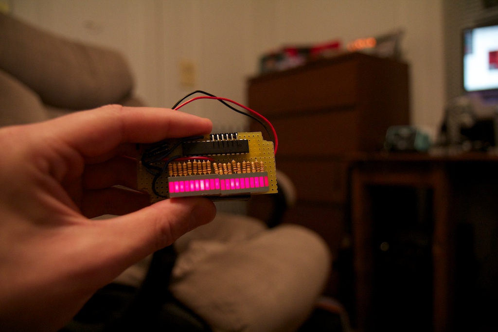
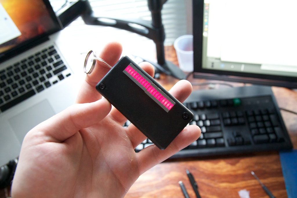
Here’s the finished board:
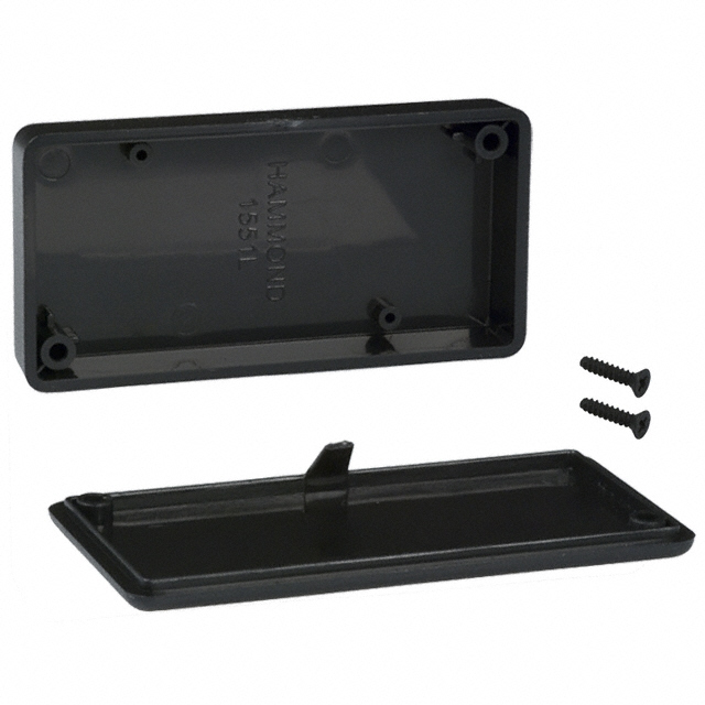
I had one of these cases lying around:
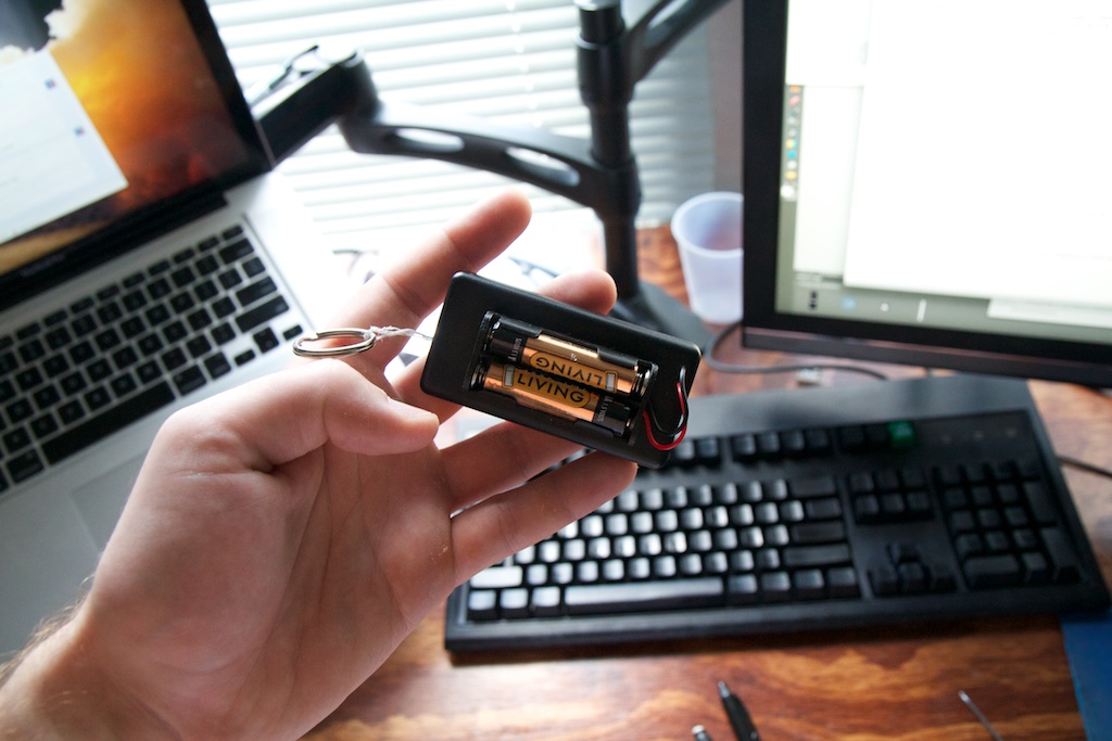
And milled it up using my hand-mill to cut a hole for the display. I mounted a battery clip onto the back using some super glue and a single nylon screw (I only had one):
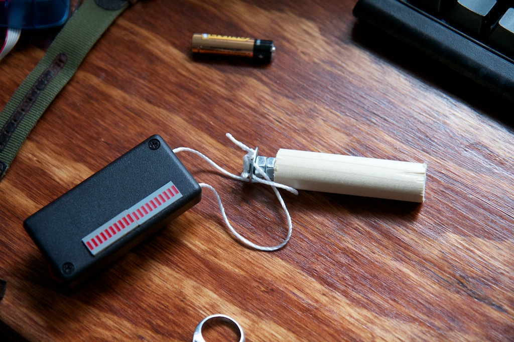
As you can see, there is a keyring attached with dental floss to one side (I said it had to be stuff in my apartment!). The idea was that you could spin this thing around on your finger. I found that this didn’t work for a number of reasons (namely, the dental floss would make its way through the keyring and the device would go flying across the room), so I made a quick trip to home depot and made this for the ultra low price of $2:
I cut two holes in a washer and tied a line through them. I then fitted the washer on to a bolt and threaded two nuts (to lock them in place) making sure to leave a gap between the nuts and the bolt head so that the washer could freely rotate. Finally, I glued the bolt into a piece of wooden dowel using wood glue. The end result worked really really well and was easy to hold. I was afraid that the device would tend to twist and turn its back on the viewer (making it impossible to see), but because I could space both lines apart like this, that wasn’t an issue.
And here’s a video of the end result! (there’s no audio)
As you can see, it automatically scrolls through a number of patterns. I actually had space on the device for about twice as many, but I couldn’t think of anything more to display, so I left it as is. Another thing to notice is that the text “DANCE!” is fairly difficult to read. For complex images and text, some method of reading position data and controlling the LEDs to hold the image steady is important. As long as the image is reasonably steady, the viewer’s brain should lock on and stabilize it the rest of the way. This way they can see the image for multiple passes and have more time to read it. I’ll have to keep this in mind for my future persistence of vision projects.
I am extremely impressed with how well this thing turned out. The entire project time was about 15 hours. I started it at 3pm on Saturday and gave it to my friend by 7pm the next day. She loved it!
P.S. The music note pattern is backwards. Fuck.
Project files can be found here: POV toy package v1.0


Pingback: Longboard Wheel Display | ch00ftech Industries
Years ago I saw stationary led persistence of vision light led sticks that would rely on people scanning their eyes to see an image. I would like to commission having some large led “sticks” made, perhaps 5′ + in height for use in a gorilla advertising campaign. The displays would need to use white less and a simple fixed text message. If this is a project you can accomplish please contact me. Thank you.
You might want to check out my FAQ page.
Pingback: Rolling Shutter Display | ch00ftech Industries
Pingback: Rolling Shutter Display » Geko Geek
Pingback: PrintSnap Instant Camera | ch00ftech Industries
I want to make oscillatory LED display not rotary
the point is i want to make the oscillatory magnetic engine that will be needed to vibrate or oscillate the LED bar for my LED display is any body can help for the Electronic Circuit and the Electric Magnetic coil
I already built the controller and driver for LED display
I hope to have any contact for help
my Skype: nshahbo
E-mail: nshahbo@yahoo.com
Nasser
how would you go about making it shift patterns based on a button press and counter variable?
say 4 patterns and cylce through?
also you explained this 100000 times better than other blogs and in a way less condescending tone. Thank you.
Thanks for the kind words!
I recommend checking out my posts on the “icebreaker 2.0” and skateboard wheel display. I think they do exactly what you’re looking for.