If you were alive in the late 90s, you probably remember this iconic commercial for the Jetta:
My goal for this next project is to make that happen in real life. Well…just the windshield wiper part.
After a whole slew of hurried projects, I decided to take a step back and make something a little more complicated that I can blog as I design.
Concept
So the goal here is to replace the typical power source of my windshield wiper motor with something with more fine control of wiper speed. There will be two circuits involved here: One will stay under the hood of the car and deal with all of the actual motor control while the other will sit inside the passenger compartment and offer controls to the driver. These two will be connected over RS422 for communication.
The user will be able to set the desired windshield wiper tempo and it will try its best to match. I might also throw in some audio processing to attempt to automatically detect song tempo though this might be difficult to do with the limited capabilities of the AVR.
User interface
As far as user interface goes, I’m imagining a little box situated somewhere on the dashboard that includes the following features:
- 360 potentiometer for fine adjustment of wiper speed
- LED bar graph for displaying current speed
- Tap-tempo button for setting tempo
- Tap-tempo indicator LED
- Microphone with some filtering similar to the light up jacket for realtime beat tracking
- Audio gain control
- VU meter bar graph.
- USB connection (through FTDI chip) for realtime interrogation/control
- Power switch to toggle back to normal wiper control function
My idea is to pretty much pull out all the stops with this thing. Some of these features I might not even end up using, but there will be a lot of unknowns in this project, so I want to be ready for that. For example: I’ve never attempted any kind of complex audio processing like beat tracking, but I figured I’d throw in the mic while I’m at it in case I want to try to make that work.
Because I’ll have to do most of my firmware development inside my car (as opposed to comfortably on my desk), I added the FTDI chip to help in debugging.
I really want this thing to look good and operate well, so I will be taking some extra measures to boost the user-friendliness of the UI.
Motor driver
Windshield wiper motors are worm gear motors with a huge speed reduction (around 50x). The results is a huge amount of torque with a slow speed. You can read all about it here. To control this motor, I will be building a synchronous switch-mode motor controller.
My biggest concern is getting position feedback from the wipers themselves so I can tell how far along in their cycle they are. When looking for more info on windshield wiper motors, I found this page. Apparently wiper motors are commonly used by hobbyists when making animatronic Halloween decorations. On Page 2, the author shows a pinout of the typical wiper motor. There are five connections:
- Ground
- Power fast
- Power slow
- Feedback switch pin 1
- Feedback switch pin 2
So, when you change the speed on your windshield wiper, you’re actually just changing between the two different power pins on the wiper motor. Presumably, they are internally wired up through a different number of motor windings to offer different speeds.
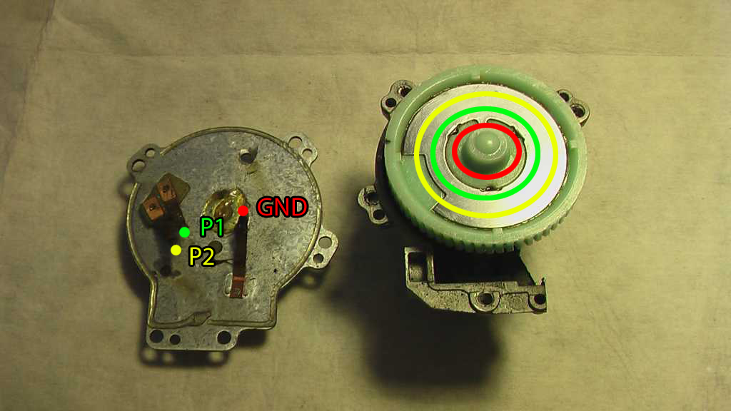
The two feedback pins are connected together for about 90% of the rotation. When the wiper blades pass through the parked position, they are opened. This function is designed to aid in parking the wiper blades at the bottom of their swipe. This is called a “parking switch”. This website has a lot of useful information on this feature including the following image which I have doctored up to clarify connections:
What you’re looking at is the gear that the motor’s worm gear drives. Along this gear is a metal conductive plate to which GND, P1, and P2 connect via little copper brushes. As you can see, contacts P1 never leaves contact with the plate. P2 breaks contact for maybe 10% or so of the cycle, and GND only contacts the plate briefly.
This implementation makes driving the typical intermittent wiper mode very simple. Motor power can be run through contacts P1 and P2 and it will be automatically cut as soon as the wipers reach their parked location. What’s more is that if P1 connects to the motor (and P2 to the power supply), it will be grounded briefly by the ground connection which will act as a brake stopping the motor immediately rather than letting it wind down. With this setup, all the controller has to do is drive the motor temporarily to get it started on its way, and it will stop all on its own.
I won’t be using that feature exactly, but it’s still pretty cool to learn about.
Lastly, whatever I do build will be done in such as way as to not interfere at all with typical wiper function. The plan is to connect to the motor through several relays which can be switched back and forth to allow my controller or the standard controller to drive the blades.
Feedback control
This is where I’m most concerned about this project. It would be very difficult to get the wiper blades running at the right speed if I didn’t have some sort of feedback information about what exactly they are doing. Ideally, I would have some sort of position encoder that would tell me exactly where the wiper blades are as they rotate, but I really don’t want to overcomplicate the design, and I can’t even imagine where I’d put a durable position encoder on the wiper blades anyway.
This means that my only source of feedback is the aforementioned parking switch pins of the wiper motor. At first, I thought I would only be able to get wiper position information at a single point of rotation, but further examination of the parking switch shows that I’ll actually be getting two: when P1 and P2 close and when P1 and P2 open.
See, the big problem is that supplying power to the motor at a fixed duty cycle does not guarantee a constant speed coming out of the wipers. With different weather conditions, the wipers will move easier or harder with the same driver settings. Because of this, I will need to create some kind of feedback control scheme.
The nice thing about this system is that it’s first order. There isn’t any inertia to worry about; the wipers will move at a speed proportional to the driving duty cycle regardless of how fast they were moving the previous cycle (there might be a tiny amount of inertia, but given how much damping force there will be, this is likely negligible). What is less nice is that the duty cycle/wiper speed relationship is likely non-linear, so I can’t expect to see the wiper speed double if I double the duty cycle.
Now, signal processing has always been my weak spot, but my current idea is to just have the driver calibrate itself in realtime as it runs. It will clock every wiper cycle and attempt to make adjustments for the next cycle to get closer to the target frequency. If the duty cycle/wiper speed relationship turns out to be linear, this could be very easy.
The end result is that the wipers will need to run for a few cycles before they get the tempo right. I might be able to reduce this delay if I use the fact that the parking switch actually gives me two instances of position data every rotation. I can run some mid-swing calibration.
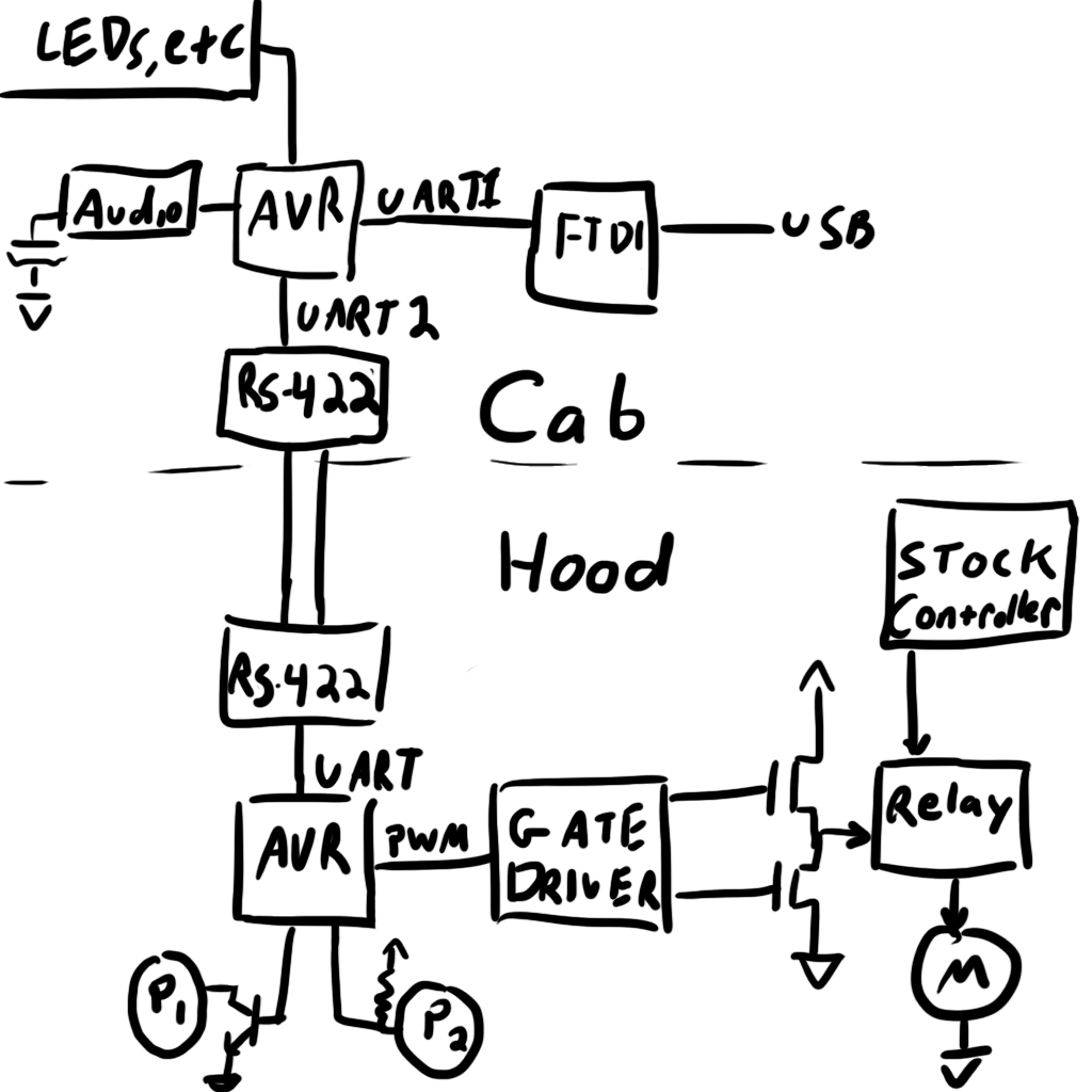
Functional diagram
Because this post has a dearth of pictures, here’s a doodle to tie everything together:
Now I just have to wait for the weather to clear up so I can get started! Keep an eye on the blog (or my Twitter) for updates.
Continue this story here.


Hi, I found you on hackaday.com. I just wanted to say your project is totally awesome. I’ve always enjoyed the brief moments when the wipers (and blinkers too) coincidentally fall into synch with a song, but as you know, those moments are short lived.
I hope you post all the code and details after you’ve perfected it.