So, last night I posted a video cataloging my creation of a radial spinning disk display (that’s what I’m calling it anyway). It’s not really a new concept or anything, and wasn’t particularly hard to make. That’s why it was the perfect candidate for the video which I think turned out rather well.
I was so excited about finishing the video, that I decided to post it before I had a proper writeup. That’s what this post is for.
Because you can find details on how a radial spinning disk display (or “hard drive clock“) works all over the place, I thought I’d make this sort of a “meta” post and try to catalog not only the project but all of the design decisions (right and wrong) that I made along the way. If you’ve been bored stiff by my super technical posts recently, this should be a welcome departure. I made sure to include tons of photos.
Concept
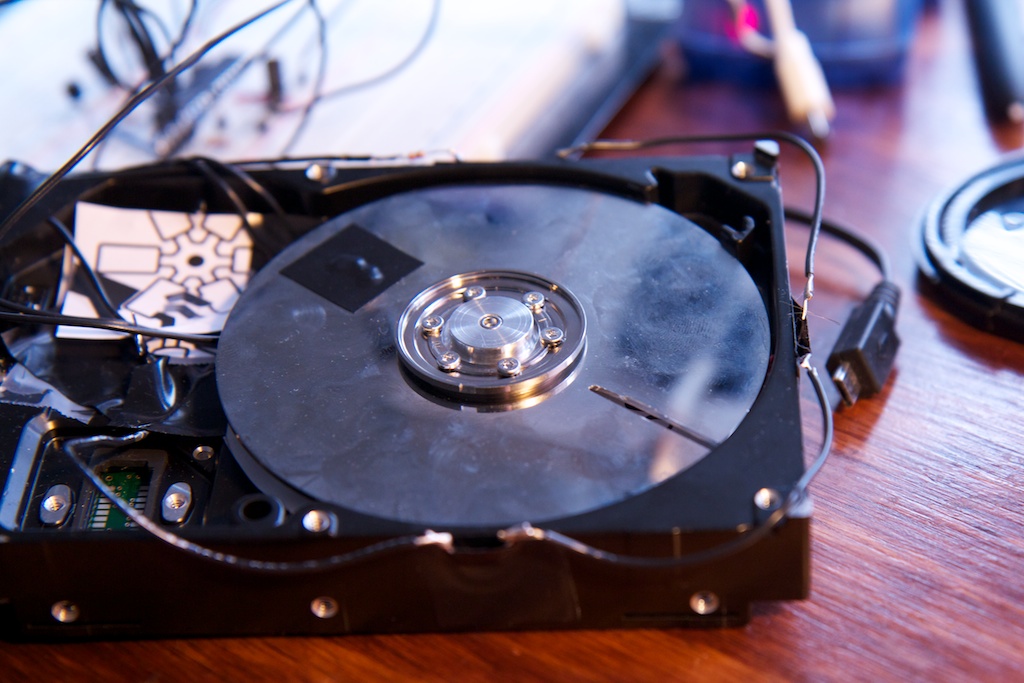
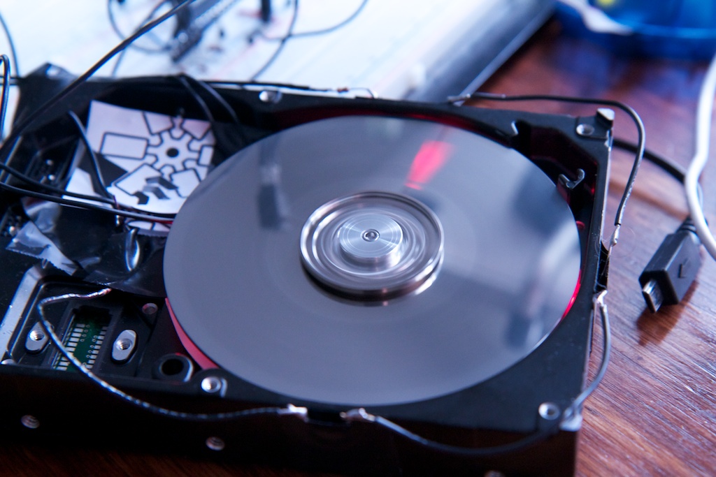
A hard drive clock is a persistence of vision device that uses a spinning disk with a slit cut in it to cover up a precisely timed strobe. The disk is spun up to a fairly high speed (in this case, 7200RPM) and every time the slit passes a certain point, the strobe is flashed by a micro controller.
Because your eyes are relatively slow to react, you see the light that shines through the slit as a steady beam. By varying the timing of the strobe, you can “move” the light beam around the disk and change its thickness.
Inspiration
I first heard of the hard drive clock idea back in high school before I knew how to do any of the stuff I do now. I’ve always had it in the back of my mind as a fun project to build, but I never thought to actually try to make one until it came up in a discussion with a friend on Tuesday. I decided that I wanted to build one that night so I could show it to him the following day.
I needed a departure from my time-vampire EL panel project anyway, and this was a welcome distraction.
The original idea was to make a full-featured display that could do RGB color and complex patterns. As you’ll see, I had to make some sacrifices to meet my self-imposed deadline. I don’t feel bad about that though. This was only meant to be a simple proof-of-concept and it certainly served that purpose.
Hardware
First, I needed a hard drive to play with. I found an old 40 gig 7200RPM IDE hard drive in a pile of computer junk and decided it was a perfect candidate. I also got an old ATX PC power supply with molex connectors to power it.
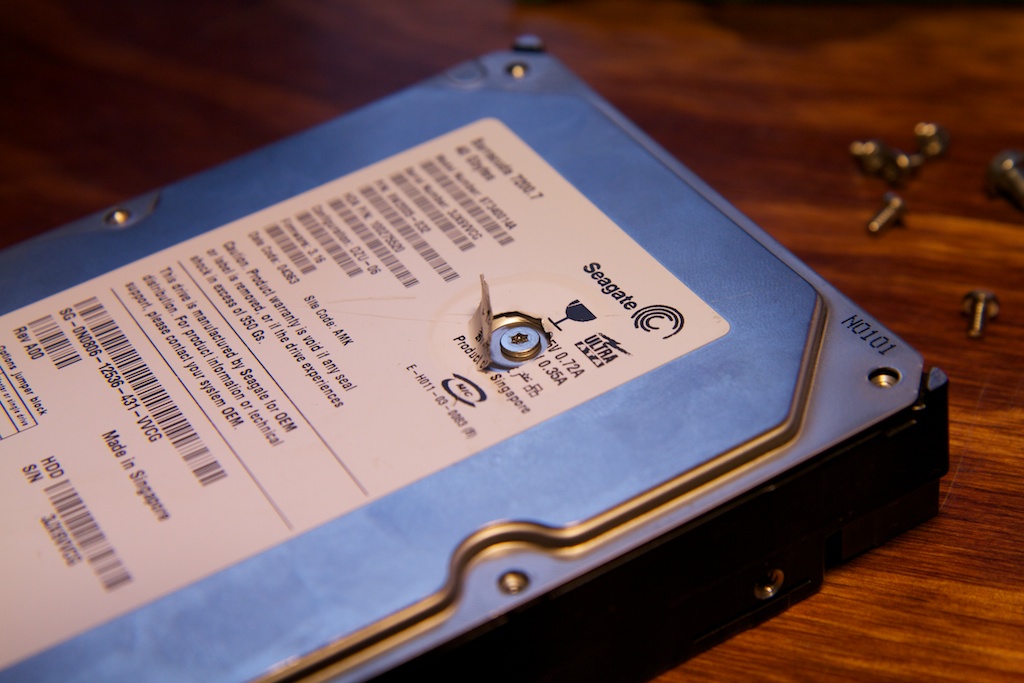
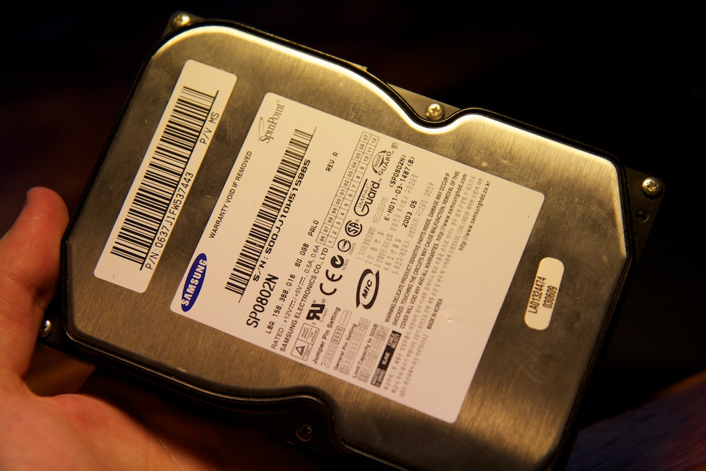
The hard drive was held together with a few Torx screws. I fortunately own a Torx driver set, so getting it apart was trivial. You just have to remember that they always place a screw under the sticker so an RMA technician will know when a user has attempted to open the drive (and voided the warranty).
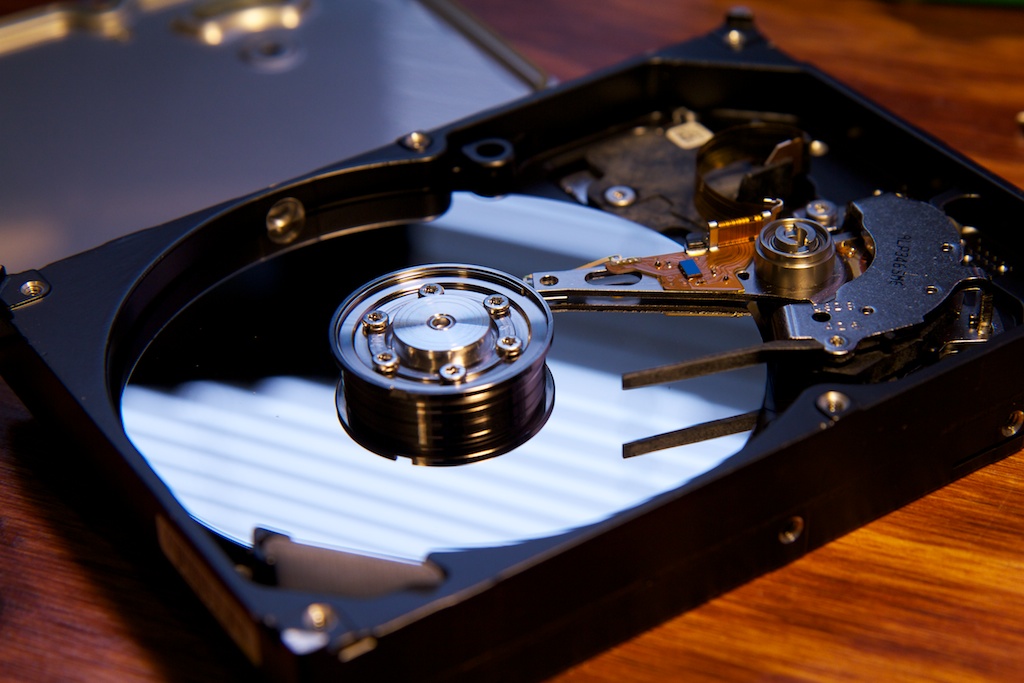
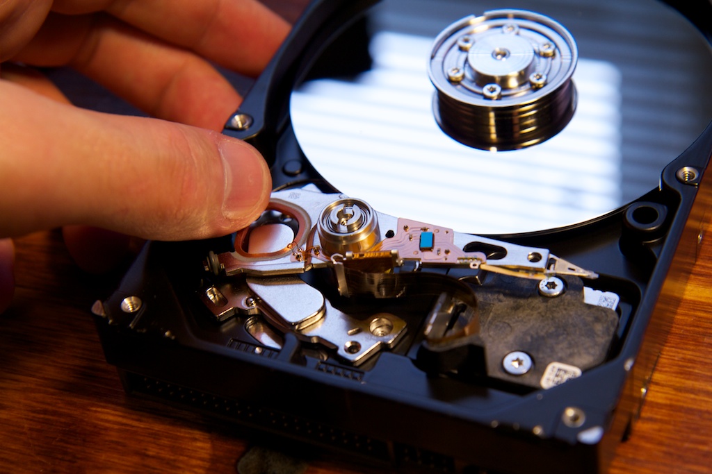
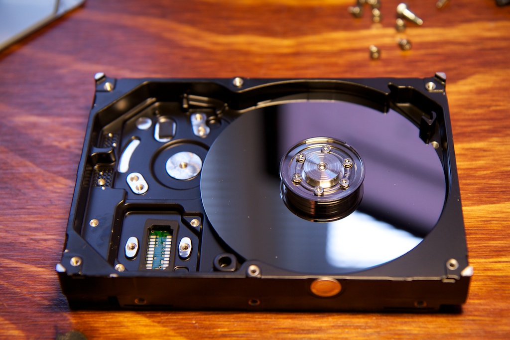
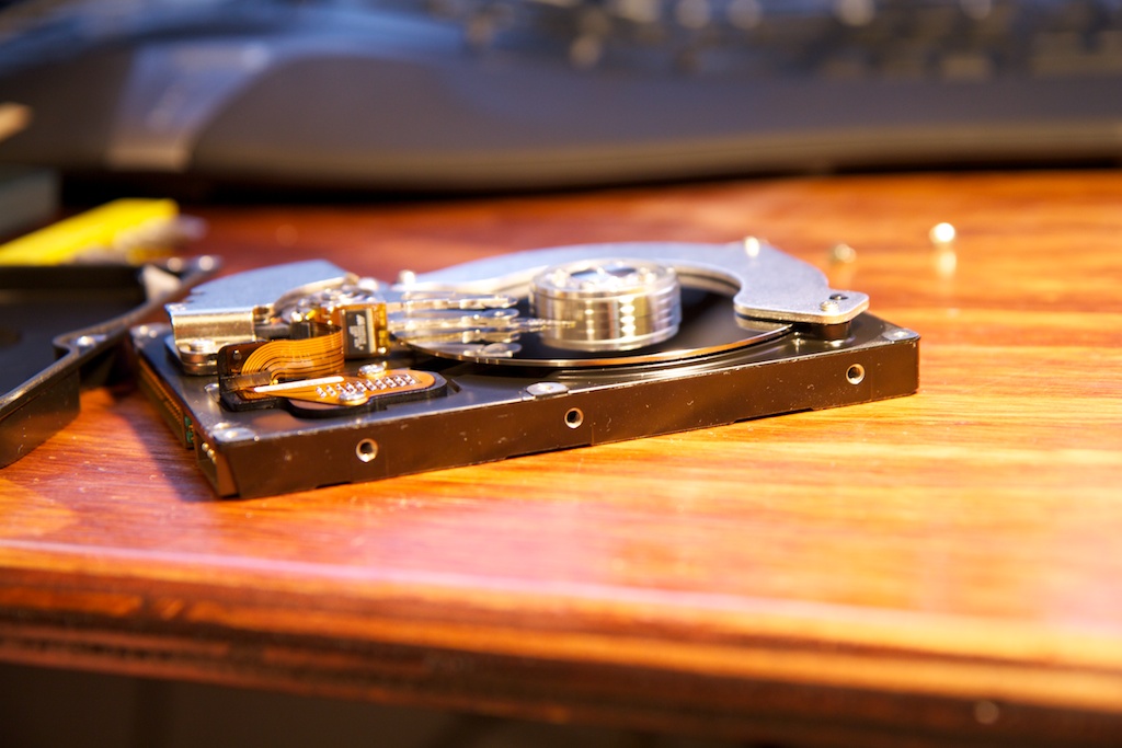
Here’s the inside of the drive:
Removing the hardware was pretty easy. There were just a few screws scattered around. In fact, the drive head magnets were only secured by a single screw counting on their magnetism to hold them in securely.
The drive head components connected to the controller board on the bottom of the drive through a clever little header that was easily removed: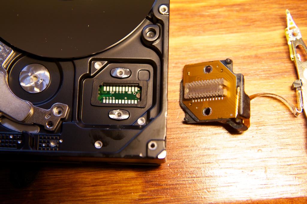
I was happy to find that the hard drive would still spin up with none of the drive head components. It seems that the controller board automatically starts up the disk upon power up presumably because it doesn’t want to waste any time as the computer is booting. I did find that the drive stopped spinning after a minute or so. I guess it’s an auto-shutdown to save power or reduce wear on the drive.
If I was looking to make a more permanent display, I would have to find a way to defeat this auto-shutdown mechanism, but 60 seconds is more than enough continuous operation time for a proof-of-concept.
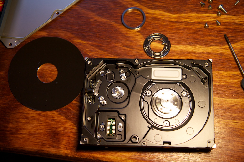
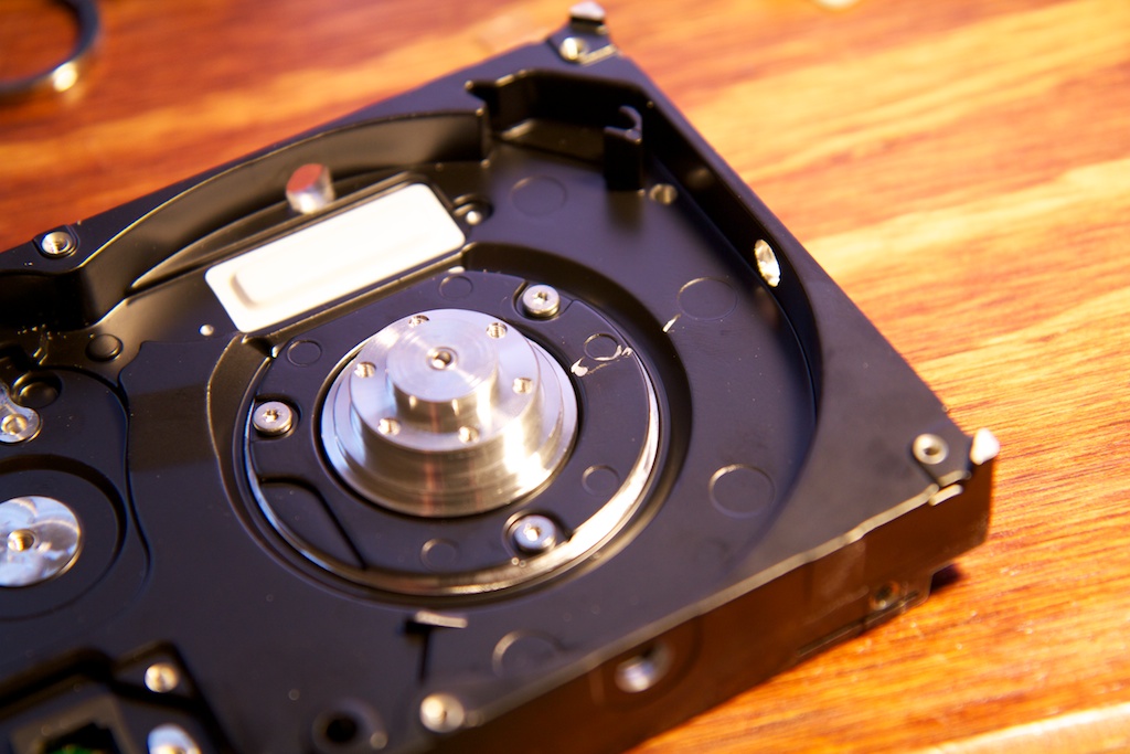
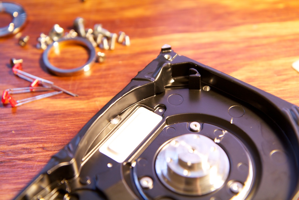
I was disappointed to see how little space there was under the drive platter. My LEDs definitely wouldn’t fit with that little room. Fortunately, there was a spacer ring on the drive spindle between the platter and the “hubcap”. Swapping the platter and spacer gave me a lot more space under the platter:
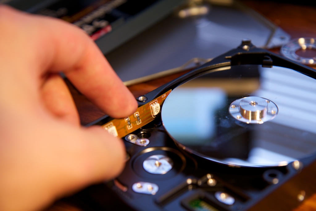
My original plan for lighting was to use the same LED strips I used in my DJ jacket. I found that the thickness of the LED strips was perfect to adhere to the walls of the drive bay and sit flush, but unfortunately the LEDs were too thick to fit between the platter and the side walls:
Still in a hurry, I found another candidate drive and hoped that this one would have more space:
40 gigs more in fact!
The second drive was held together with Philip’s head screws and came apart just as easily as the first. The inside didn’t look much better though as the sidewalls were attached to the top of the housing which left the drive platter very exposed.
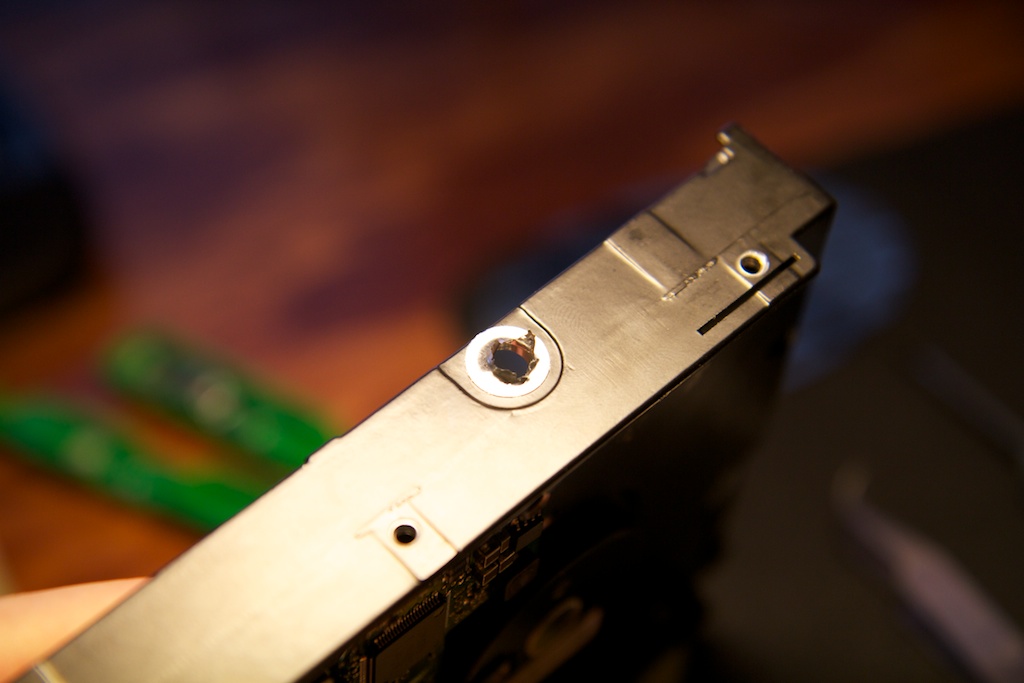
I was hoping for something more enclosed, so I reverted back to the original drive. I noticed a hole in the side wall of the original drive that was covered with a thin piece of foil that was easily removed:
I don’t really know what this opening is for, but it sat tangential to the disk, and was in the perfect location to allow an LED to shine through. Hard drive enclosures are usually made of aluminum which is a very soft metal. I was able to drill two similar holes on the top and left side with a hand drill:
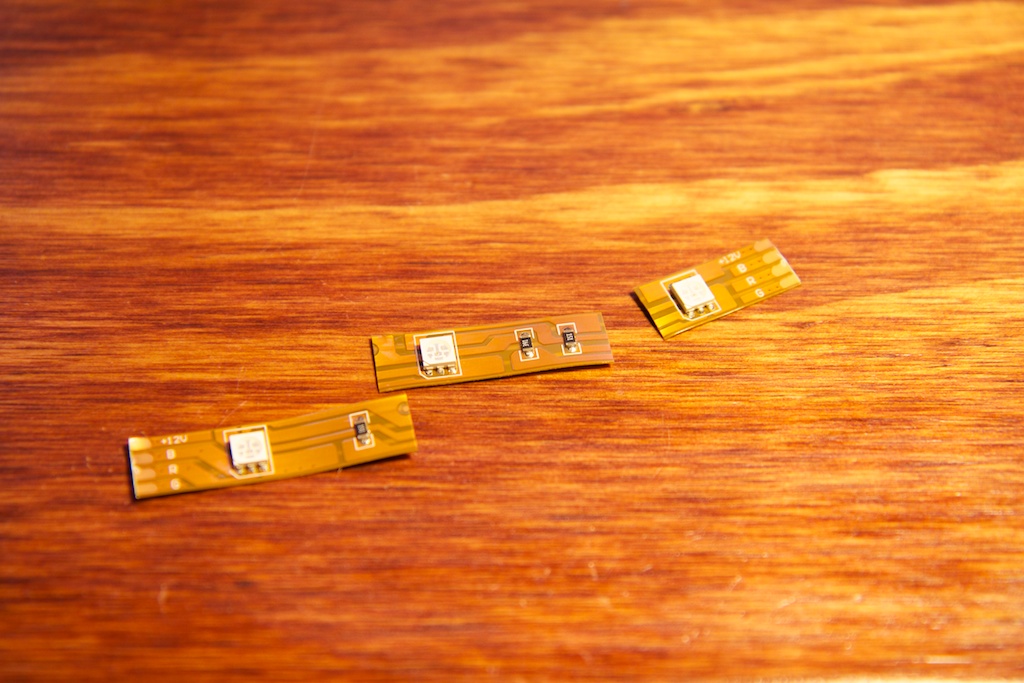
The LEDs on my strips were the perfect size to shine light through these holes, but the space between the LEDs was too small. The LED strips are assembled into 3-LED segments and provide solderable tabs at the ends. My thought was to cut one of these strands into three sections:
And then carefully scrape off the protective Kapton tape layer to expose the copper so that I could solder wires between them. Unfortunately, this was pretty much impossible. The tape is too strong and too well adhered. I quickly scrapped this idea and moved on.
I didn’t have any other RGB LEDs on hand, so I decided to drop the G and B and just use some high-intensity red LEDs that I had lying around. I decided to ditch the holes and just tape the LEDs to the sides directly. Taping the metal leads flat against the drive bay would provide ample support and keep the LEDs from moving around.
To protect the LEDs from shorting out on the metal hard drive bay chassis, I covered all the relevant surfaces in electrical tape:
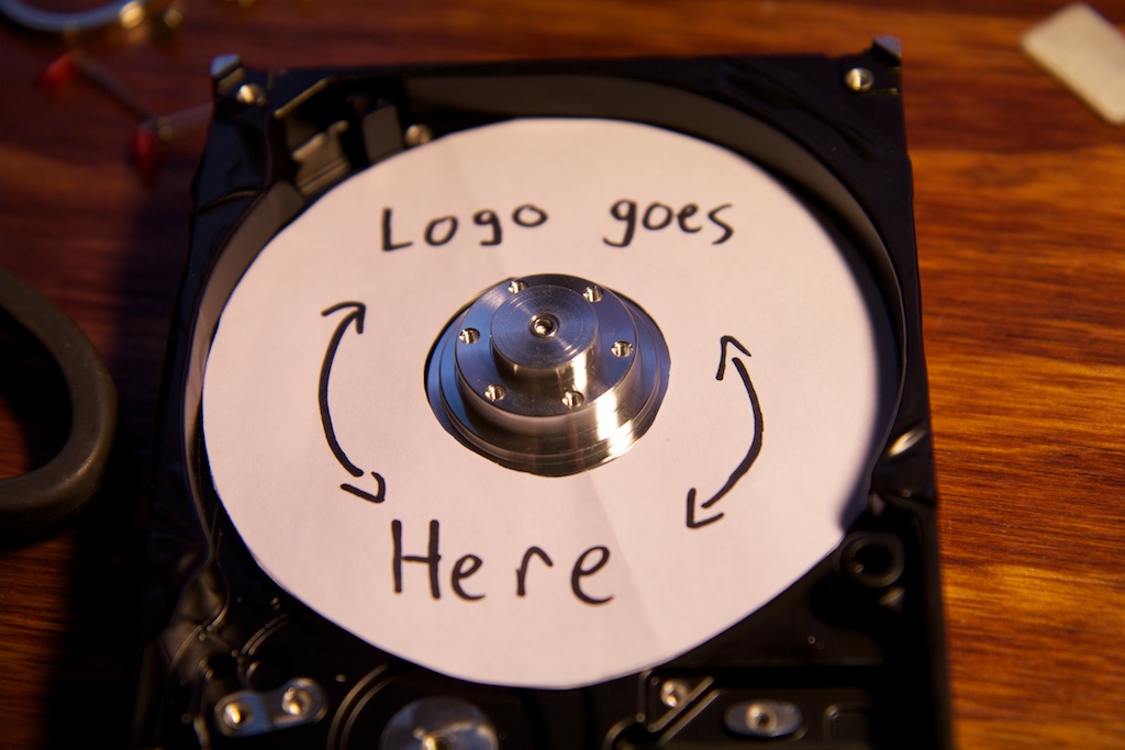
Before inserting the LEDs, I realized that I would need something reflective and diffuse to bounce the light off of. The black hard drive bay wasn’t going to cut it. I traced the hard drive platter itself onto a piece of printer paper and cut it out. I had to widen the center hole a bit though so it would fit around the spindle without touching. I glued it to the bay using rubber cement.
The “Logo goes Here” markings were to serve as a proof that the light displayed by a hard drive clock can be textured by simply having some patterned surface behind the spinning disk. Rather than just seeing a red line, the viewer could see a textured red line.
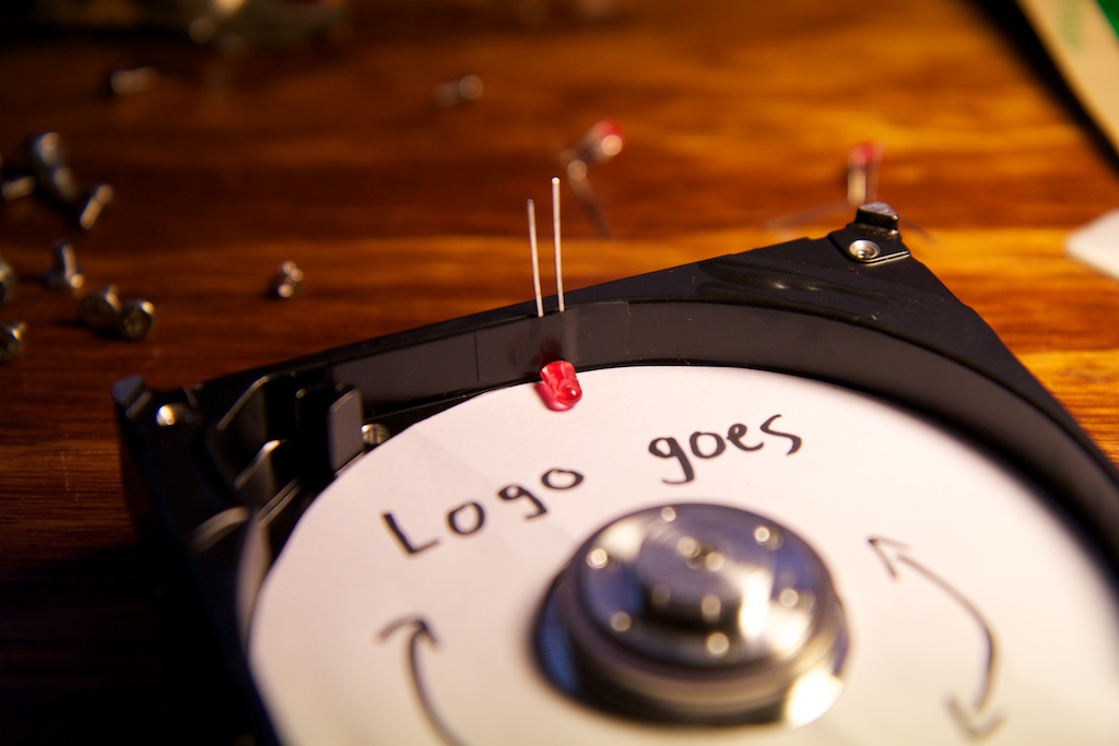
Now back to the LEDs. I taped one in place to see how it would fit:
But I found that the clearance between the platter and sidewall was so tight that the thin lead and two layers of tape were too thick to fit. This means that I’d need to use the holes I had drilled. To keep the LEDs from shuffling around, I just poked them through the tape that I had already placed over the holes:
I did the same thing with the other two holes and just taped the fourth LED down:
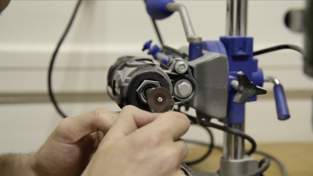
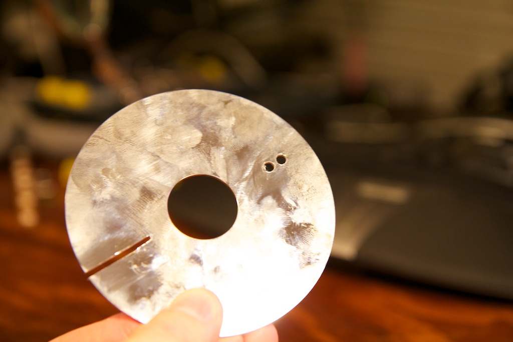
With my LEDs all set up, I wanted to see how they would shine through my platter as it spun. I used a dremel tool with a ceramic cutoff wheel to cut a slit in the platter that extended most of the way to the center. I wanted to leave plenty of the center of the platter intact, because removing too much would make it too fragile and possibly cause it to shatter when spinning.
The platter fit perfectly over my LEDs with no rubbing.
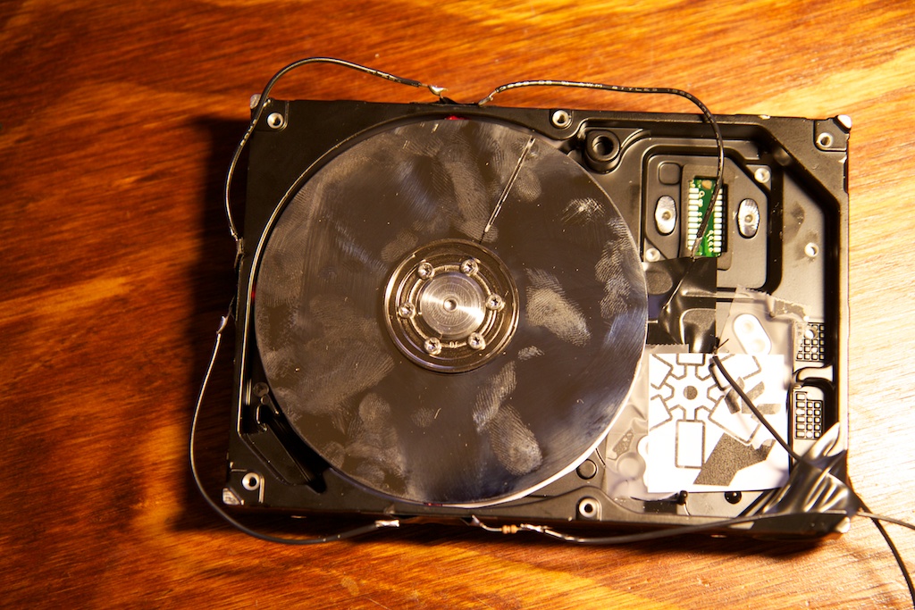
Adding this slit altered the structural integrity of the disk and also offset the balance. To make sure the disk would survive, I first spun it up in a safe location where it couldn’t damage anything if it broke. After seeing it spinning, I decided to add a little warning sign…
Because the power supply would be supplying 12V, I decided to wire up my LEDs in series to simplify wiring. Each LED has about a 2V drop, so four in series drops me 8V. The other 4V were dropped across a 300
![]()
resistor also in series. This works out to about 13mA of current which is fine for LEDs.
Next up was adding the optical sensor. In order to control the flashing of the LEDs appropriately, I would need some way to send a signal to my micro controller once per cycle. I achieved this using an optical sensor similar to the one I used in my IceBreaker project. I actually had a few through-hole versions lying around as I have plans to teach a seminar during which the class will assemble their own through-hole version of the IceBreaker.
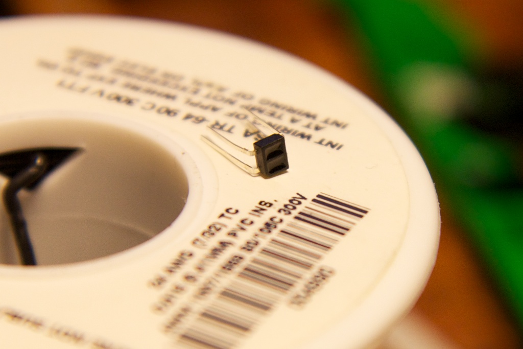
This sensor is simply an infra-red LED and an infra-red phototransistor. When light from the LED reflects into the sensor, it will pass current and pull down a data pin. When the light does not find its way into the sensor, no current passes, and an external pull-up resistor pulls the data pin high.
The shiny surface of the disk offered an excellent reflective surface for the sensor. To offer a non-reflective section, I added a piece of tape and drew on it with black Sharpie. I figured that the slit would also act as a non-reflective surface, and since I didn’t want to have two blips per cycle on my data line, I positioned the tape so that it was flush with the slit.
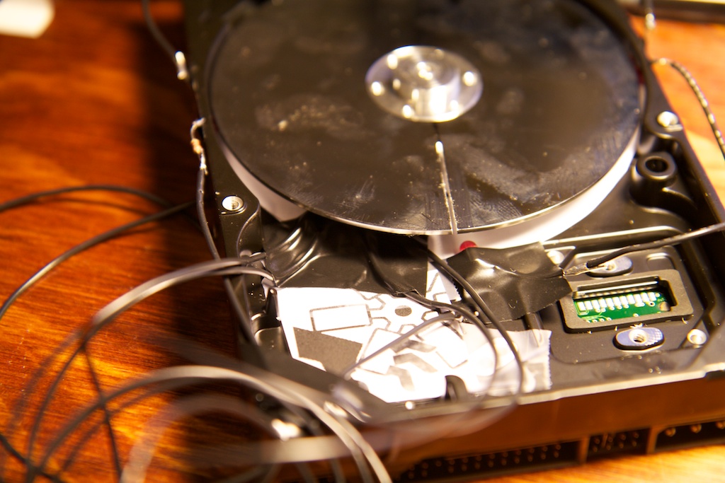
I bent the traces of the photosensor so that I could slip it under the disk and have it facing up. I then soldered wires to the photosensor leads and taped it down under the disk.
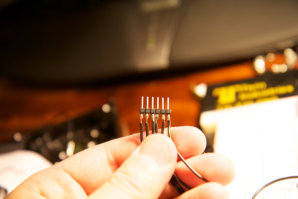
I now had six wires coming off my circuit board: two from the LEDs and four from the sensor. In hindsight, I could have placed the sensor’s LED in series with the red LEDs, but…too late now I guess.
The cathode end of this series was eventually connected to ground through an NPN transistor. The base of this transistor was connected to an output pin of my micro controller. I couldn’t connect the LEDs directly to an IO pin because I was afraid that it wouldn’t be able to deal with the +12V that would be presented to it when no current was flowing through the LEDs and therefore no voltage was being dropped.
To manage all of these wires, I soldered them to a header that could be easily plugged into a breadboard:
The hard drive could plug directly into one of the power supply’s Molex connectors, but in order to power my breadboard circuit, I needed a way to connect it to the other Molex. I opted to just solder the wires directly. Red is +5V and yellow is +12V:
Now I had to rig up my PC power supply to manually turn it on. It used to be that PC power supplies routed all of their power through the switch on the front of the computer. This is why older computers would always say “It is now safe to turn off your computer” while shutting down. They needed a human to physically press the button and cut power.
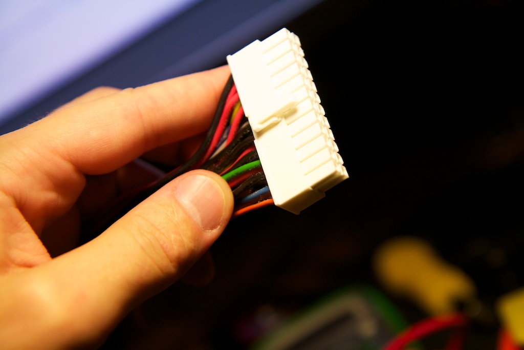
This became problematic when computers started needing a lot more power as running that much current through a switch could cause a fire hazard. Newer “ATX” power supplies have an internal switch that is activated by connecting a certain pin on their motherboard headers to ground. The pin is usually green in color and it’s always located in the same place:
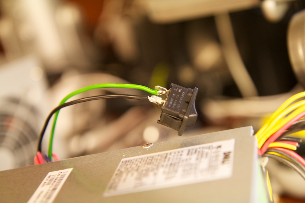
Up until this point, I just shoved a paperclip into the green terminal and one of the black ones, but that was getting clumsy, so I opted to cut the header off and connect those two wires through a switch:
I connected the 6-pin hard drive header to a bread board and routed power to the LEDs from the 12V rail. The 5V rail powered the IR LED through a current-limiting resistor. It also pulled up my data line through another resistor.
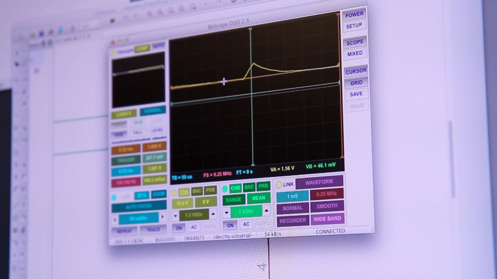
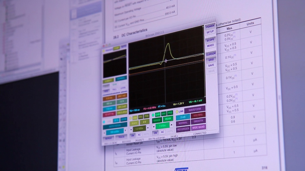
I wanted to see what my data line looked like, so I fired up the hard drive and connected a scope probe. I was expecting to see the voltage on the data pin go high for a short period of time once per cycle. Unfortunately, this “blip” was far to small. Even at its highest point, it wasn’t high enough to get picked up by the micro controller.
To fix this, I started to adjust the current limiting resistor and pull up resistor. A smaller pull up resistor pulls up harder the voltage. This means that your blip will rise faster when the phototransistor is turned off (the light is blocked). This unfortunately also means that your minimum possible voltage will be higher because even when the phototransistor is on, it can’t sink enough current to pull the voltage down. A larger pull up resistor lowers your minimum voltage but can also slow down the rise of the blip so much that it doesn’t have enough time to rise all the way as the marker on the disk passes.
Changing the current limiting resistor on the IR LED has similar effects as more light means a harder pull down and less light means a softer pull down.
No matter what I did to adjust these values, I couldn’t get the blip to look much better than this:
Where the lowest point is 1.3V and the highest is around 2.5V. This isn’t a very good range for the input of a micro controller, so I decided to take a different approach.
Firstly, I realized that the tape was not sufficiently absorptive to fool the IR sensor, the sensor registered the Sharpie mark the same way it did the rest of the platter. That means that it was only actually registering the very small slit in the platter. The slit was so small that the IR light was able to spread out on its way to the slit and reflect back on the surrounding surface, so the light was only partially blocked.
To keep the light from spreading out too much, I moved the sensor closer to the platter. All I had to do was wedge a shim under it. I opted to use the little air filter that was originally a part of the drive:
It acted like a nice little cushion. This apparently wasn’t enough, so I also widened the slit.
I was worried that taking so much weight out of one side of the drive would severely offset the balance, so I also drilled a few holes out of the other side to help compensate. Not exactly super scientific, but I figured it couldn’t hurt. To keep light from shining through these holes, I covered them in black electrical tape.
A wider slit means that the signal voltage would have more time to rise up every cycle which would raise the max voltage of my blip. It also had the double benefit of allowing more visible light to pass through. This means that my light beam would be slightly brighter once I had the drive working. Here’s my blip after these changes:
Much better.
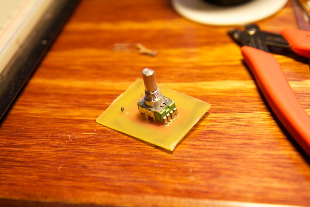
To control the light beam, I needed a potentiometer that could feed an analog voltage level into my micro controller that corresponded to its rotational position. I had this left over from an old project, so I wired it up to my breadboard:
Now I had a spinning hard disk platter with LEDs and an optical sensor and a control knob. Hardware was done!
Firmware
I’ll spare most of the specifics of the firmware’s operation, but here’s an overview of how it works.
My firmware contains a timer that counts up as the disk rotates. I included an external interrupt that resets this counter every time the micro receives a blip from the optical sensor. The length of this timer determines how long until the LEDs are turned on.
If the timer is zero, the light beam shows up immediately after the sensor. Lengthening the timer rotates the beam farther from the sensor.
When this timer is up, it turns on the LEDs and starts another brief timer. When the second timer runs out, the LEDs shut off. The length of this timer controls the beam’s thickness. Here’s a photo from an earlier test where I had the second timer set to a larger value:
The second timer’s length is fixed, but the first timer gets its length from the ADC onboard the micro controller that is reading a voltage from my control knob. Turning the control knob counter-clockwise increases the voltage being fed to the ADC and consequently lengthens the timer. Because the platter is also spinning counter clockwise, this moves the light beam to the left as well.
This algorithm is simple, but it’s not optimal. It does not compensate for fluctuations in the hard drive platter’s speed. The motor seems to follow some kind of routine where the speed will flutter approximately once every two seconds or so. This causes the light band to also flutter. To prevent this from being an issue, future versions of the firmware could measure the total length of each cycle and adjust the timing of the light pulse to compensate if the speed changes.
Here’s a demonstration of the platter working that should make this all pretty clear.
Coinclusion
Of course there are improvements that could be made, but my only goal in working on this project was to design and construct a proof of concept. Even if it did work better, I wouldn’t want to convert it into a clock or anything because even if it could stay on for longer than 60 seconds, I would still worry about the bearings wearing out extremely quickly due to the imbalance of the platters.
But anyway, I certainly enjoyed the break from some of my more serious projects, and I had a lot of fun. I hope you enjoyed reading!

