Looks like a second hand is possible after all.
Objective
Since I started development on the QR clock, one of the biggest requests has been to enable the clock to display seconds as well as minutes.
When I original wrote the clock’s firmware, it took about 7 seconds to generate a QR code. Of course, this was without refreshing the display. The display needs to be refreshed at least two dozen times a second, and these interruptions extended the QR generation time to around 40 seconds.
This was far too long to generate a QR code every second, but it could definitely update once a minute which is all that was absolutely necessary for a clock. I’ve never done something so computationally intensive on an AVR before, so I just assumed that 45 seconds was a reasonable amount of time. While it would have been nice to update every second, I was amazed I got it to work at all.
Later, I saw a comment on one of the Hack-A-Day posts that got me thinking:
Regardless of the fact that my clock doesn’t meet the guidelines for border thickness, he linked to a library that was supposedly able to generate a QR code in less than a second. This got me thinking that it might be worth trying to optimize my code before resigning to a once a minute update.
With my shipment date just around the corner, I thought it’d be fun to discuss what I discovered.
Auto-Optimize
The first step was to change the compiler settings. A compiler is a piece of code that takes human readable code and creates machine readable code. It’s not a super straight forward process though because there are often multiple ways to achieve exactly the same outcome, and the compiler has to decide which method to use.
Say for example that you have a function that returns two times its argument:
return 2*x;
This function is small and simple enough that when your compiler turns it into machine code, it may choose to “inline” the function. This means that the function’s operation (that single line) will be literally copied and pasted into every spot that it’s called from. This has the advantage of reducing the amount of time it takes to call the function (no need for time-wasting jumps to the location where the function is stored), but it increases the size of the program by storing another copy of the function every time it’s called.
Like I said, the compiler has the option to do either, and you can often guide its hand by setting your compile time flags.
I was surprised to see that my Makefile called avr-gcc with the -Os flag set. This flag compiles the code optimizing it for space. At the cost of speed, it tries to make the program as small as possible. With just an 8k program on a 32k micro-controller, I figured I had plenty of space to stretch out and speed up.
I changed the -Os flag to -O2 which allows for small optimizations for speed. This increased the program size by about 1k, and increased the speed by a similarly unremarkable margin.
I then changed the flag to -O3 which had a drastic impact. It optimized the code well enough to generate a QR code in about 1.5 seconds, but it also ballooned the program size up to a wholloping 27k! It took about 30 seconds to program and verify it was such a big file.
It was nice to see that the compiler had a lot more to offer than I originally thought, but it still wasn’t perfect. The compiler can try to remove redundant and unnecessary program loops and inline some functions, but it isn’t smart enough to recognize what it is I’m trying to do and find a faster way to achieve the results I need. For that, I’d needed to change my code by hand.
Besides, 27k is absurdly large.
The Usual Suspects
To get an idea of how long particular functions were taking, I connected my oscilloscope to the exposed Tx and Rx lines and wrote a simple set of functions that let me toggle these pins. By inserting these function calls into my code, I could determine how long the function they surrounded took to operate.
My first inclination was to attack the functions that are called the most often. My first target was the screen refresh function which is called dozens of times every second. Considering the refresh rate seemed to have the largest bearing on the QR generation time, it seemed like an especially fitting start.
In addition to refreshing the display, every time the full display is refreshed (8 calls to this function as the display is scanned in 8 lines), a measurement is made from the ADC to adjust the display brightness to match ambient light.
IISR(TIMER2_COMPA_vect)
{
if (col<7)
{
    col++;
}
else
{
    //only update brightness once per refresh
    if(!(ADCSRA & (0b01000000))) //Is the ADC done?
    {
    ADCSRA|=(0b00010000);//CLEAR FLAG
    OCR0A = convertbrightness(ADCH);
    TCNT0 = 0;
    ADCSRA|=0b01000000; //START ANOTHER CONVERSION
    }
    col=0;
}
printrow(&masterimage[col*9]);
displayenable(0);
setcol(col);
storageclock();
displayenable(1);
}
There were a number of things I could fix with this function. Firstly, because I control the refresh rate manually, there’s no reason to check to see if the ADC is done. I am certain that enough time has elapsed for the ADC to complete a measurement.
I took a look at the setcol function. This function set which of the 8 columns the display is writing to.
void setcol(uint8_t column)
{
    uint8_t order[8] = {0,4,2,6,1,5,3,7};
    PORTB = ((PORTB & 0XF8)|(order[column]));
}
The look up table is provided to account for the strange ordering of the displays due to layout limitations. Although it might not seem like much, in this implementation, this array must be created every time this function is called. I improved time by making the array a global variable static variable (Thanks Alex). This means that the array will be created just once when the function is first called.
Just these two changes changed my refresh time from 108
![]()
s to 76
![]()
s.
To be honest, I was proud of this increase at the time, but I had no idea exactly how poorly optimized the rest of my code was.
Penalty Box
To introduce this next part, I need to give a little background on how QR codes work. The QR code pattern is generated by a computer with some complicated mathematical algorithms. It’s designed to allow for a large amount of corruption without losing the message. Unfortunately, it doesn’t automatically account for its own machine legibility.
Looking at a QR code, you might be able to imagine what kind of things could severely confuse a computer:
 For example, if exactly the right kind of data was fed in, it’s possible that the random bits of pixels at the bottom right might start looking like one of the localization boxes present in the other three corners. Such a thing might confuse a QR reader.
Likewise, large sections of black or white pixels with no interruptions might also make it difficult for a reader to determine exactly where the pixel boundaries lie.
For these reasons, every QR code generated from the algorithm has to have a mask pattern applied to it. This image from Wikipedia demonstrates these different mask patterns:
If you look at the eight options on the right of the image, these patterns are overlaid onto the QR code and every time a black pixel appears, the corresponding QR code pixel is reversed.
The hope is that when a QR code is potentially difficult for a machine to read due to the types of reasons I mentioned, applying one of these mask patterns will scramble it enough to fix that. The QR code also encodes which mask pattern was used so that the scanner knows how to make sense of it.
Of course, in order to determine which mask pattern is best, a good QR generator needs to try all eight options and score them all in some way.
The standard method is to perform four different tests. Whichever pattern scores the least number of penalty points is the best option.
- Gain points for large arrays of consecutive white or consecutive black pixels.
- Gain points for 2×2 boxes of the same color.
- Gain points for patterns that look like localization boxes showing up.
- Gain points for having an uneven representation of white and black pixels.
I won’t go into the details of exactly how many points are assigned for each of these infractions, but you can read all about it here.
The Squeaky Wheel
When I first set out to do this optimization, I assumed that my incredibly poorly optimized code generation and frame buffer implementation was responsible for the delay. What I found when I measured the code was that the penalty scoring section of code was taking up almost all of the 40 second generation time!
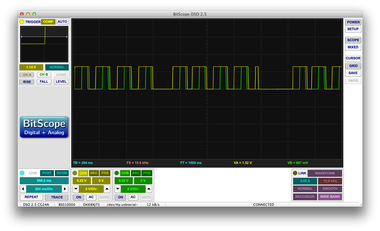
I captured one such penalty scoring section on my oscilloscope:
The yellow section represents the time spent applying penalties, while the green section represents the time spent applying penalty 3 alone! Considering that each of these operations takes about a second, and it must take place eight times per QR code, it’s definitely a good place for improvement.
Penalty 3
More specifically, mask penalty 3 is looking for vertical and horizontal arrangements of pixels that look like these:
And adding penalty points every time one is found. To be clear, there are 4 white pixels to the right and left of the pattern respectively.
Firstly, for some unknown reason, I was also checking for this:
I have no idea why I was searching for this pattern, and removing that search reduced the penalty time by a third.
Secondly, it became immediately clear why this operation took so long. In short, my code was scanning through the pixels and comparing the previous 11 pixels with the desired search pattern. Keep in mind that every pixel comparison required a call of the “getbit” function which is a nontrivial function that extracts a single bit from a byte.
This means that in total, the getbit function was called somewhere in the ballpark of 2904 times every time a QR code was generated.
My solution to this problem was to do a running comparison between the desired pattern and the QR code. Basically, I compared pixel 1 of the pattern to pixel 1 of the QR. If they match, I move to pixel 2 of the pattern and pixel 2 of the QR. This continues until a complete match is found or it isn’t at which point the pattern is started back at the 1st pixel.
There were a few special considerations that had to be taken into account for this to work though, and it’s a classic example of faster code being more meticulous and less elegant than slower code.
For example, using this method, the second pattern would fail if there were 5 white pixels in a row followed by the design. In order to accommodate an arbitrary number of white pixels before the first black pixel, I made a special update that prevents the pattern from failing in this scenario.
Likewise, very particular pixel orders could cause the first pattern to miss targets. If a portion of the QR looked like this:
The pattern would fail and reset on the second white pixel and then fail again on the black pixel triplet. I had to implement a particular check for exactly this kind of failure.
Furthermore, I made another check to prevent the code from continuing to look for the pattern in a row if there wasn’t enough room left in the row to complete the pattern.
With all of these changes in place, penalty 3 operates much faster as you can see here:
A Few More Changes
With penalty 3 trimmed down to size, it was time to attack the other penalty methods. Each of them takes a rather large amount of time, and they’re each called 8 times per code. Although the clock must be able to produce a QR code within a second given a worst case scenario, I thought it might be a good idea to reduce the generation time for more ideal situations. Perhaps a future application of my algorithm will need the fastest QR generation possible rather than just needing it to fit inside a generous second.
To improve time, I had my code perform each test separately and evaluate the score between them. If the penalty score of the current mask pattern is already higher than the previous best, the code stops applying penalties and moves on to the next mask pattern. There’s no need to continue applying penalties when a particular mask has already lost.
There are numerous other minor changes I’ve made throughout the code, but I’m not going to bore you by mentioning them here. If you’re interested, I recommend checking out the completed code that I will be posting to the blog shortly.
I’m a Dope
At one point, I was considering optimizing the code by “cheating”. Technically speaking, applying any mask pattern is correct. Given a clear enough image, any mask pattern should resolve with a QR scanner. The only point of the penalty system is to choose the mask pattern that will resolve more easily/quickly.
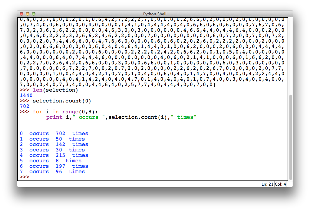
During my investigation, I wrote a program that would run through all 1440 minutes in a day and return a count of how many times each mask pattern was chosen. I came up with this:
AS IT TURNS OUT
If you happened to download my main.c code from my original QR Clock post, you might find this line:
if (currentscore<bestscore)
{
    bestscore=currentscore;
    bestmask=i;
}
Which is run after the score of each mask pattern is determined to hold on to which one has currently scored the best. After this has iterated three times however, the following routine is run:
adddatabits(&outputmatrix[0],&outputarray[0]);
addtypeinformation(&outputmatrix[0],0);
applymask(&outputmatrix[0],0);
printcode(&outputmatrix[0]);
Apparently at some point in development, I modified my code so that it always uses mask zero in the applymask function. This went unnoticed all the way through development probably because as I said, any mask pattern is technically correct, and on top of that, code 0 would have been used a majority of the time anyway.
Fortunately, this bug didn’t make its way into the actual QR clock, so the one that’s been sitting on my wall for six months has been doing it right all this time.
Conclusion
Optimizing code is a lot of fun. There are a few times where it pays to understand exactly what the microcontroller is doing to shave a few microseconds off here or there, but other times, all you need to do is rethink how you’re accomplishing a task.
Generating a QR code in under a second has a ton of possible applications. I might even remove the “time set” mode and allow it to display the QR code live as the user is setting the time. That was impossible with a 40 second generation time, but only mildly inconvenient with a <1 second time.
Most importantly, this new code will allow me to have a working seconds hand on the clock. One thing I can say after looking at it though is that I will be making this an optional setting as I think that a lot of the people requesting it have no idea how goddamn distracting a QR clock can be!


Nice. Are you going to provide the source code of your optimized QR code generator?
I’ll be providing the final optimized firmware with the QR clock, but I’m not going to bother providing the optimized source code of the original generator seeing how it executes in about a millisecond on any modern computer hardware.
Fine. Just to be clear, with ‘firmware’ you don’t mean only binaries, but also C code, right?
Yup!
I’ll also be releasing some extra firmwares to enable things like RS-232 control.
I SO can’t wait for this to arrive at my desk!
Pingback: Optimizing the QR Clock Code « adafruit industries blog
Can I still preorder one of these?
I’m not accepting any pre-orders at the moment, but I’ll be selling them through my store as soon as they’re available.
They might sell out fast though, so if you want a heads up, shoot me an email, and I’ll be sure to notify you.
I’m the hack-a-day commenter.
https://github.com/tz1/qrduino/blob/master/qrencode.c
I have something where it stops if the badness is lower than some threshold with an #ifdef. Some patterns will be really bad, but “good enough” should be readable by modern scanners.
The other thing is I don’t use ANY divides. They take a long time and aren’t really needed. I also think I only have one or two multiplies, tuned for 8bit.
Interesting. In addition to removing divides, I think there are a number of 16 and 32 bit operations that can be chopped up and optimized.
I’ll be cleaning up and my optimizing my code some more before I ship, but there really isn’t much need to go totally crazy. Any application that requires a QR code faster than once a second would be too quick to scan anyway.
Why not just pregenerate all possible codes and store them in an external eeprom chip?
Because this method is more versatile, a more interesting challenge, and clearly works well enough.
Besides, if someone wanted to add a calendar function, storing codes wouldn’t really be a viable solution. A single day would take up about 5 megabytes of space to store.
EEProm is small, so I think you mean Flash. Also , due to the use of reed-solomon, one bit change changes lots and lots of bits across the image (even if you can specifiy one mask).
Conversely, because of RS, you could do a binary clock in the middle or corner (anything not the big target squares) of the QR code and it should still work.
I have a few ideas to further optimize the algorithm/implementation after reading your code snippets. Is this code on github or something?
It will be interesting to setup a bounty to look for the most optimized/speediest code or smallest code size, and the price will be a free QR clock!! You may end up being able to fit the code is a smaller chip (i.e. cost saving).
Thanks for the offer, but my current goal is to optimize for “shortest time until release”. The code is more than good enough for a QR clock. It can already produce codes faster than they can be read.
I will be releasing the final source code along with some other firmwares to help hobbyists repurpose the clock for their projects once I start shipping.
It would be interesting to see what the upload speed between screen and some smartphone or media device camera could be achieved.
You should declare in-function lookup tables as “static” instead of making them global. Better data encapsulation!
Wow! Learn something new every day. I always wondered if there was something like that, and I’ve seen “static” before, but I never put two and two together.
Remember how I’m an EE?
Thanks for the tip. I’ll update the post.
Hi!
Is there a way to obtain the latest firmware and Eagle files?
I would like to create one myself.
Everything you need in here https://ch00ftech.com/qrclock/