I’ve got a few days before my big summer vacation, so I thought I’d hammer out an incredibly impractical display technology!
Rolling Shutter
In order to fully understand what you’re seeing above, you need to know a thing or two about how CMOS camera sensors work. CMOS or “Complimentary Metal-Oxide Semiconductor” image sensors can be found in a plethora of consumer level imaging devices. Anything from cellphones to digital SLRs.
Any image sensor simply needs to provide a grid of light sensitive pixels that can record how much light hits them. Light is focused on to this sensor with a lens, and what the sensor records is reconstituted into an image using some image processing.
Now, one thing that’s special about CMOS sensors in particular is how the data is read off of them. One might expect that a photo sensor being used to take a picture (or a series of pictures in a video) captures a single moment in time. In reality, it captures an extended moment.
See, for most CMOS sensors, the image can not be read entirely all at once. Only one row of pixels can be read at a time (the exception is Global Shutter devices which you might find in high end cameras).. This means that the first row captures a moment in time very slightly before the last row. For the most part, this doesn’t really matter, but it can cause some issues when the object you are recording is moving fast enough such that it has changed locations between when the first and last row are recorded.
This is often referred to as “rolling shutter”, and you can find examples of it all over the internet:
(image credit: TUAW)
While this effect can produce some rather surreal works of art, I was curious if it could be harnessed to accomplish a specific task: creating a display.
The Display
If you read my blog often, you’re no stranger to persistence of vision displays. The basic concept behind a POV display is generating a 2D image by taking a single row of point light sources and moving it rapidly while changing its lighting configuration. In this way, a 2D image can be swept out with a 1D array.
I wanted to see if it was possible to emulate this sweeping motion with the rolling shutter of a digital camera. I woke up with this idea on the 4th of July. I don’t remember what I was dreaming about, so I’m not entirely sure if I’m allowed to take total credit for it…
By creating a vertical column of lights that can be illuminated in a very specific manner, it should be possible to draw an image using the rolling shutter effect from a digital camera. Let me explain:
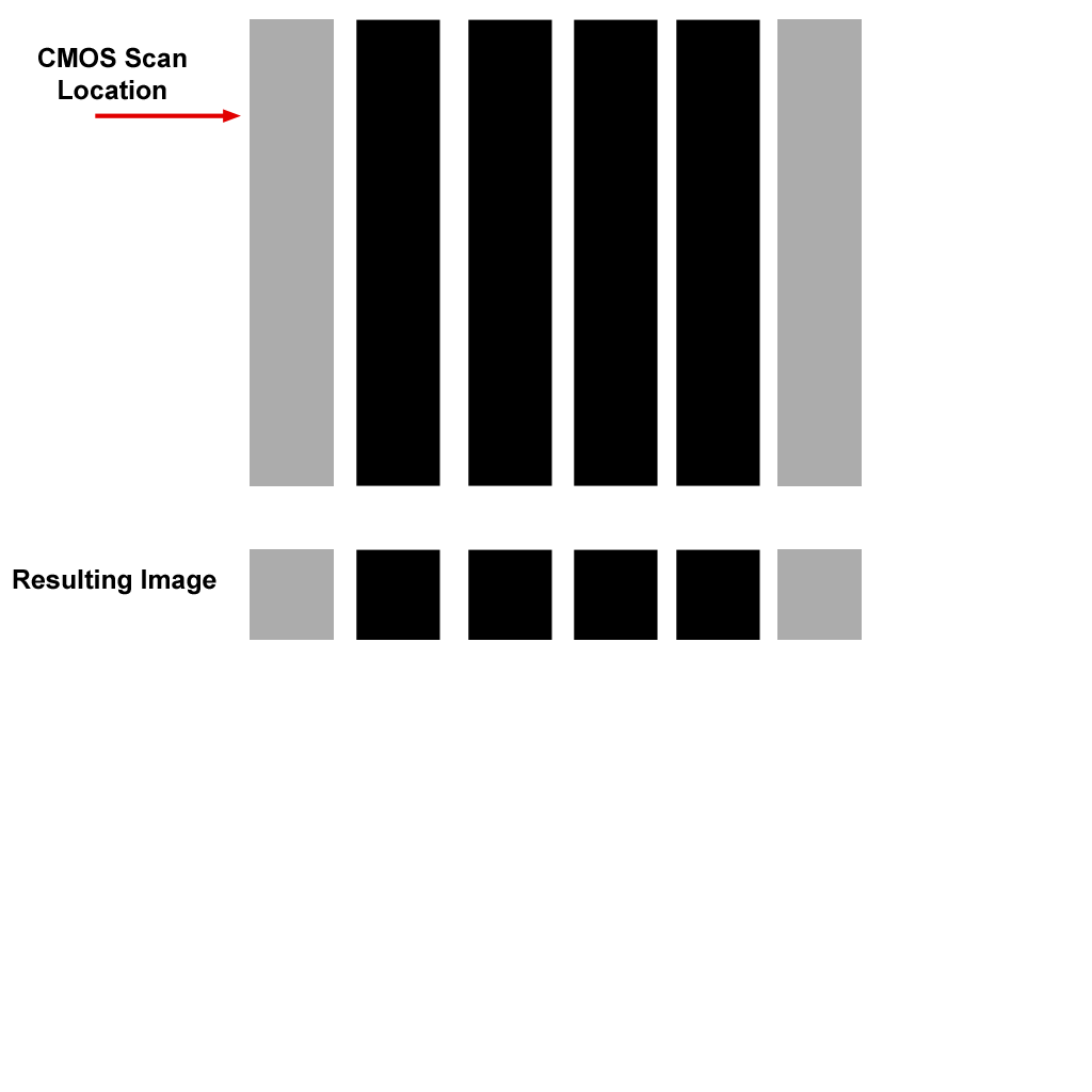
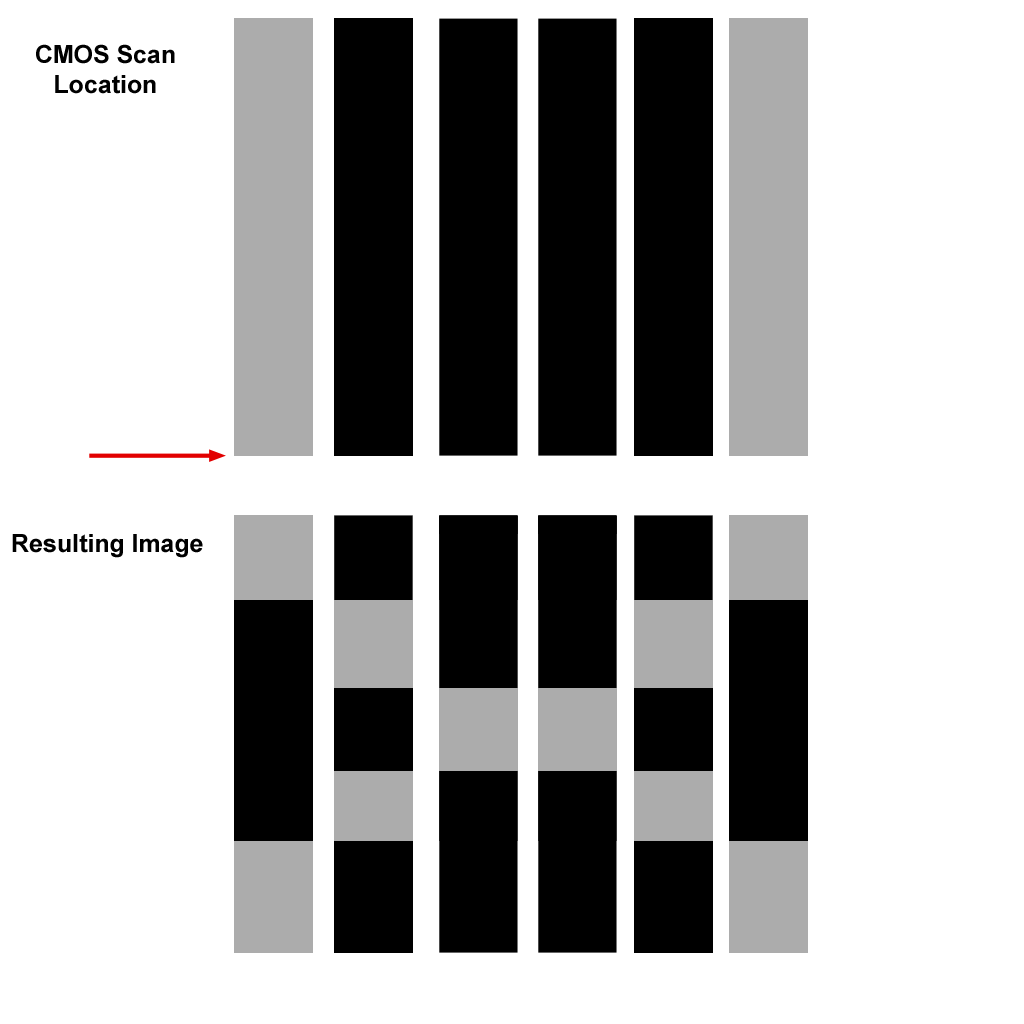
Above, you can see what is supposed to be six vertical columns of light. Each of the columns can be illuminated, but the entire column must be illuminated at once (imagine a flashlight aiming down a translucent paper tube). On the left, an arrow indicates which row of the CMOS scanner is being recorded. Below it is a depiction of what the resulting image looks like so far. As you can see, nothing too surprising. But then, mid scan, the lights change configuration:
As you can see, the resulting image now contains rows of pixels from the first configuration as well as the new arrangement. If the lighting configurations were to continue to change, an entire image could be drawn out this way:
In other words, the vertical placement and scale of the pixels is handled by the rolling shutter artifact in CMOS sensors while the horizontal placement is handled by a microcontroller illuminating LEDs.
Hardware
So to make this thing happen, I just had to illuminate a few vertical columns of light in a very particular pattern and speed and aim a camera at them. The circuit here is extremely simple (just a few LEDs), so I decided to focus a little more on the aesthetics.
In order to properly demonstrate exactly what’s going on here, I wanted to create a display out of something that couldn’t be used to display images otherwise. For example, if I used paper tubes as mentioned above, an observer may think that I had simply filled the tubes with an array of LEDs to create the effect.
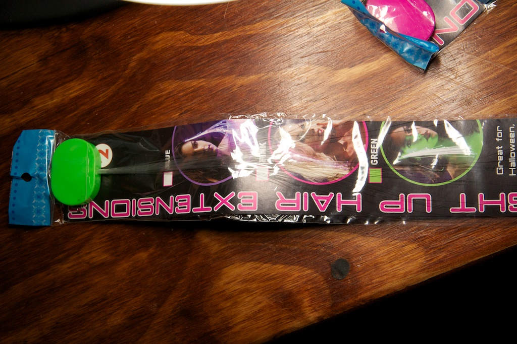
Originally, I was hoping to use some bubble lights, but I was a little put off by their price tag. Eventually, I settled on fiber optic bundles. These are the kinds of things you see all the time being sold at outdoor events during the summer. They’re very cheap, and can create a pretty neat effect. Looking around on Amazon, I found some “Light Up Hair Extensions”:
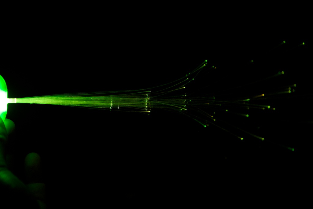
When switched on, they flash and fade in a number of colors and patterns:
Taking one apart, I found that the circuit was incredibly simple. Just an LED and some batteries:
But wait! How are they flashing and fading without some kind of control circuitry? There isn’t even a current limiting resistor! Just take a closer look at the LED:
Cool, huh?
But I digress. Ripping a few of these things apart, I came up with what I needed:
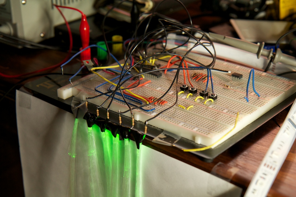
I’ll spare you most of the details, but what happened next was some very haphazard breadboarding and some taping of LEDs:
I’m visiting my family in two days, and I wanted to get this thing working before I left. Don’t judge me.
I included four user interface buttons to allow me to “tune” the display. More on that later.
Software
The software for this project was also very simple. The six LEDs of the display were hooked up to six pins of the same GPIO port. This allowed me to change all six of them simultaneously. All my software had to do was take the bytes stored in RAM and output them to that port in turn to generate the image.
The more complicated bit was the timing. When recording a video, a camera’s sensor will record an image at 30 frames per second (actually 29.97, but who’s counting?). That frequency is a standard across almost all video recording devices (in America anyway). What isn’t the least bit standardized is the scan rate of the CMOS sensor. This second measurement is critical for controlling the vertical size of the image.
Ideally, the scan rate would be infinitely fast, but in reality it will vary from camera to camera depending on the quality of the sensor. Lower quality cameras tend to have slower sensors and will record more “wobbly” video.
I set the software up with two timers. One timer fires exactly 30 times a second, and the second timer is triggered by the first and executes once for every row in the image to be displayed before quitting and waiting for the next trigger.
The four buttons allowed me to adjust the length of these two timers to “tune” the image to exactly where I wanted it.
Is it Practical?
When I started this project, I was thinking about applying this technique to artwork. Imagine a giant vertical sculpture in a night club that looks like a bunch of columns of light that fade in and out, but when you look through your cellphone’s camera, you see an image! Cool huh? Sure, you couldn’t make an pattern that displays exactly the same image on everyone’s phone due to the aforementioned differences in CMOS speed, but you could probably have it progress through various speeds so that people would eventually see something clear if they looked long enough. Heck, the distortion caused by viewing the image at the wrong speed might look kind of neat on its own.
Looking at the video, this might seem pretty feasible, but there is one detail that I didn’t mention, and it has to do with how cameras deal with changes in subject brightness.
With a digital and film camera alike, there are only a handful of things you can do to limit how many photons strike the sensor or film and how they affect the resulting image. You can adjust the sensitivity of the sensor or film, decrease the aperture size (make the sensor peer through a smaller hole), or simply limit the amount of time you expose the sensor to light.
In the case of a SLR, this last one can be problematic. The actual mechanism that moves to expose the film or sensor to light can only move so fast. It may take longer just to open the shutter than the entire exposure is supposed to last! Take a look at this video:
You can see that this problem is solved by passing a small slit of open shutter over the image sensor. This way, any given pixel on the sensor is only exposed for a brief period of time, but they are exposed at slightly different times as the shutter moves. Sound familiar?
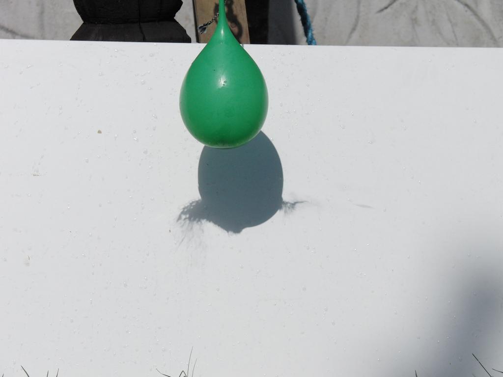
This is how the image from this thread was captured:
The ballon started to pop when the shutter’s gap was in the middle of the image. Note that the image isn’t blurry because each pixel was only exposed for a very brief period of time. It’s just…a little wonky. As a brief side note, this is the same reason why DSLRs can’t operate with a flash with an exposure set faster than 1/200th of a second. Since the flash is only a few microseconds long, only the area under the gap in the shutter at the time of flash will get exposed properly. Under 1/200th, the curtain is actually fast enough to expose the entire frame simultaneously before firing the strobe.
As it turns out, this same problem exists for cellphone cameras that have no moving parts. Just like the shutter curtain, a CMOS sensor can only “move” so fast. Unlike SLR cameras, cheap cellphone cameras cannot adjust their aperture, and while some work can be done to increase the sensitivity of a sensor by applying gain, not a lot can be done to decrease it once the subject is bright enough. The only alternative is to adjust the exposure time. This is where the wonkiness comes in.
What does this have to do with me?
Well, in order to get a proper exposure in low light environments, a camera’s sensor is going to increase its exposure time as much as possible. In the diagram above, I used a red arrow to indicate exactly where the pixels were being read from, but in reality, there should be two arrows. One arrow turns on the sensors, and a later arrow collects data from them. The resulting image will be a time average of all of the light that hit the pixels between these two arrows:
The end result is that the light configuration will change between the time when a pixel is activated and when its data is collected. That means that the pixel will contain an average of data from both configurations. The image will appear blurry and there will be some vertical overlap.
For the video I showed, I used a fancy video camera that let me manually set the exposure time per frame. By decreasing the exposure time, I was able to force those two arrows close together to minimize overlap and blur (coincidentally, this video camera was actually DSLR though for video mode, the mechanical shutter is locked open, and the shutter speed is controlled by the CMOS sensor).
In most cameras however, the user has very little control over the exposure time. In very low light situations, the exposure time will be so long that the camera will have time to activate all of the pixels before it even begins to collect data. In some cases, each pixel might be averaging the data from every light configuration instead of just one or two.
The only way to force a cheap camera to quicken its shutter speed is to expose it to a very bright light source. This is why most of the super weird images you see are of things like airplane propellers in broad daylight. Under dimmer conditions, the user might just see a blurry propeller as one is accustomed to seeing with a naked eye.
So if I wanted to install something in a night club and have it work with a wide variety of the cameras one would expect to find there, I would need a display bright enough to rival the Sun, and that’s not the kind of thing people really want in their night club.
Conclusion
So the moral of the story is that this thing really isn’t very practical at all. It was just a quick and dirty project, and I’m kind of glad I got something working without spending too much time/money on it just to be let down.
It was also a great review of how camera sensors work which is knowledge I might be putting towards a future project.
Plus I have some cool leftover light up hair extensions!








Pingback: Ghostly images captured only on camera
Pingback: rndm(mod) » Ghostly images captured only on camera
Pingback: Ghostly images captured only on camera - RaspberryPiBoards
Pingback: Ghostly images captured only on camera | Blog of MPRosa
Pingback: Ghostly images captured only on camera | Daily IT News on IT BlogIT Blog
Your writing style is awesome and I’m glad you pointed out the chips in the LEDs… Is there a way to test if that chip also carries a current-limiting resistor? Just a random thought!
Very neat work, as usual. 🙂
Pingback: Ghostly images captured only on camera | Make, Electronics projects, electronic Circuits, DIY projects, Microcontroller Projects - makeelectronic.com
Pingback: Using a Camera's Rolling Shutter Effect to Create a Display
Pingback: Using a Camera’s Rolling Shutter Effect to Create a Display | News Vault
Excellent writeup, really interesting! I really like the nightclub idea. I wonder if cellphone cameras expose enough control through the application API that you could write a viewer app for this kind of thing. If you could force all cameras to use the same “shutter” speed through the app, you might be able to make it work for a number of devices.
Pingback: Noticias breves de la semana (29) - ALTFoto
Girişimcilik
Herkesin anlatacak bir hikayesi vardır diyerek çıktık bu yola. Motivasyon, Dert Ortağı, Umut arayışlarınızın bir parçası olmaya geldik. Sizde Sitemizi ziyaret ederek kendi hikayelerinizi anlatabilirsiniz. Sma Hastalarına umut olabilir, bir çok konuda bilgilenebilirsiniz.