
Remember me?
Background
When I was a kid, every Christmas would involve a trip to Coleman’s Nursery to see all of the creepy animatronic Christmas decorations and drink hot coco.
That’s me on the left: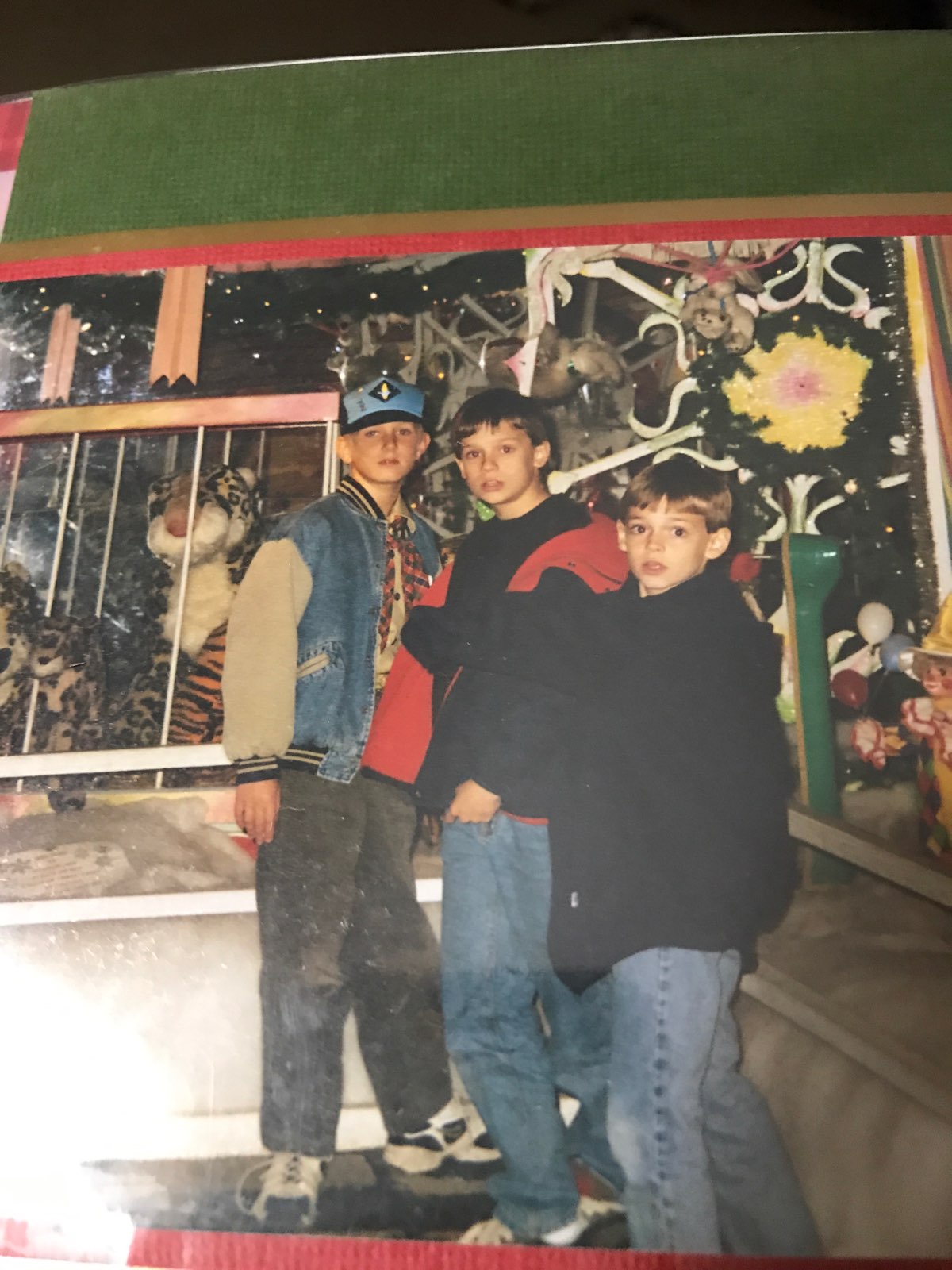 Sadly, Coleman’s closed up in 2003, but my memories of the place are still vivid.
Out back, they had a pretty great nativity scene surrounded by some lovely bushes shrouded in net lights. Net lights were a relatively new thing back in …1998?, and many people enjoyed the ease of spreading a blanket of evenly spaced lights over their plants rather than stringing them by hand.
The Coleman Nursery net lights were special though because they were animated! Thinking back on it, they must have been wired up similar to typical “theater chase” Christmas lights with three phases played in series so they appeared to move but in a grid instead of a line. It was a really excellent display for a ten-year-old’s eyes.
While the animated patterns were certainly engaging, there was really only one possible pattern that was hard-wired into the lights. As a kid, I always thought it would be neat if they could show an arbitrary pattern.
This was roughly 20 years ago back before LED lights were a thing, and definitely before individually addressable LED lights were a thing. I thought it’d be fun to revisit the idea and see what could be done with today’s technology.
LED Displays
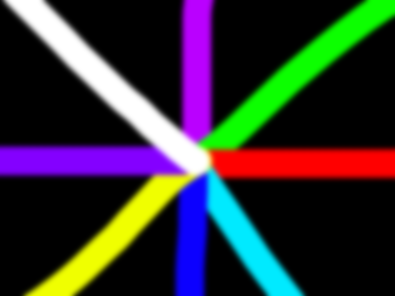
Speaking from a high level, the purpose of any kind of display is to trick your brain into thinking you’re seeing a real object or scene. Over the years, display technology has developed different ways to take advantage of your optical system to present a realistic image.
Rather than displaying a whole gamut of color, modern displays just use Red, Green, and Blue (matching up with the wavelengths your eyes detect); rather than showing a moving object, a display will show a series of static images relying on your brain to piece them into smooth movement.
Taking this one step further, the human brain is great at identifying patterns. For example, look at this shape:
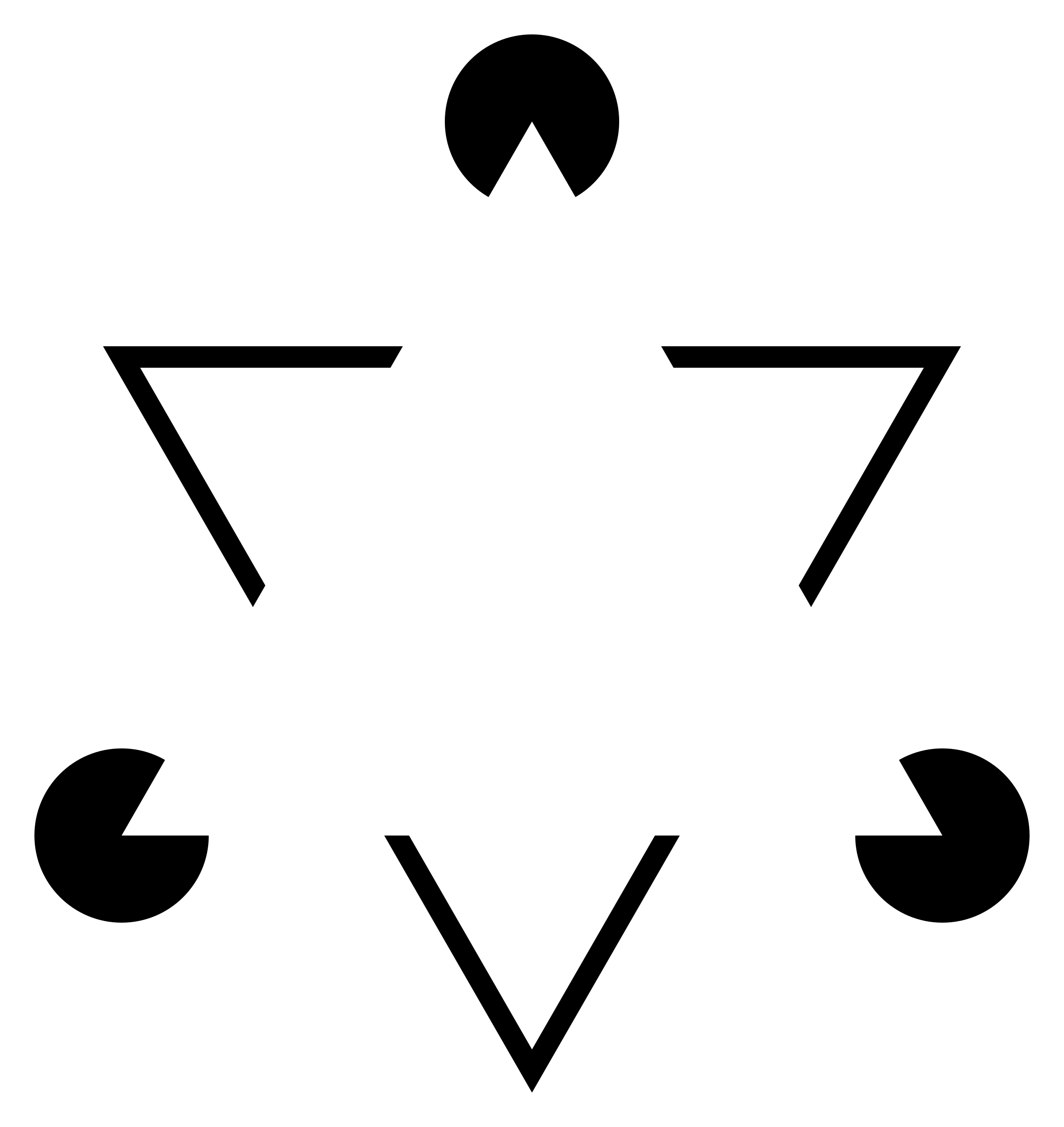
You might see a white triangle. In fact, it’s just a few Pacman shapes and some V shapes. It turns out that you only need to hint at a shape for your brain to piece it into the complete form.
The screen you’re looking at right now is incapable of displaying round objects like the letter O. It can only illuminate pixels arranged in a square grid, so any round shape is an approximation based on some clever math. If we can represent arbitrary shapes on a square grid, what about a non-square grid? or even a non-uniform grid?
When I left college, I started applying for jobs and finally got a phone interview with Newark, the electronic component distributor. It was only on the night before my interview that I realized that I had in fact not applied to the electronics distributor Newark, but rather the DJ equipment company Numark. I went through with the interview anyway, and since it was the only offer I got, I took it. I’ve since called it my mulligan job.
Numark turned out to be the main brand under which several other brands operated. One of them was Akai Pro, makers of the lovely MPC Renaissance.

On the left there, you will see 16 knobs that can be assigned to various audio processing functions. Over each knob are 15 LEDs which are software controlled, and can display information regarding the status of each knob (gain, L/R fade, etc).
After powering up the MPC Renaissance, it will enter “Vegas Mode” before it connects over USB. Vegas Mode is meant to flash a bunch of lights and make the device look alluring in the storefront of your local Guitar Center or whatever (for real, I don’t know anything about music production, I just worked there). Pay close attention to the knob LEDs in the video below:
If you look carefully, you’ll see that they spell out “A K A I.” To this day, this is my only real original contribution to a consumer electronic device. I was bored at work one day and figured out how to do it. They liked it so much that they shipped it like that. The animation alone takes up about half the firmware space.
On the off chance that nobody would believe me, I did this on my last day of work:
In software, each of the 240 LEDs are mapped to their associated knob and ordered by their location in the 15 LEDs around that knob. That isn’t to say they can’t be controlled arbitrarily however, and with a little Python, they can be controlled as shown above to show arbitrary images or animations.
At the time, I think I wrote a pretty clumsy program to help me manually map each of the 240 LEDs to their physical locations on the device (I remember clicking a lot). Looking back on it now, I think the process can be streamlined and even made consumer ready for arbitrary LED arrangements.
LIKE CHRISTMAS TREES!
User Experience
Animated LED lights certainly aren’t new, but they typically animate relative to their order on the strand. Your run-of-the-mill addressable LED strand will come with a controller box that has dozens of animations such as theater chases or rainbow fades, but because the controller doesn’t know how the LEDs are oriented, the overall appearance will depend on how the LEDs are strung up. It ultimately only works when they’re in a straight line.
The only exception to this are systems that constrain the location of each LED light such as these new gross “Tree Dazzler” things I’ve noticed this year:

Yay! Plastic!
The goal for this project was to create a system by which a non-technical user can randomly string LEDs throughout a tree or bush in a traditional fashion, point a camera at them, and then see them animate in interesting ways that are not possible with typical LED strand lights.
Hardware
So the hardware for this project is pretty light. As you may have noticed, I’ve been a little busy lately and haven’t given my blog the attention it deserves. Still though, I think this post hi-lights a proof-of-concept that could be streamlined into a pretty slick hardware device as I’ll outline in the conclusion section.
LEDs
I’ve actually been sitting on this project idea for a few years now. In fact, the LED strips for my party lights were originally purchased for this project, but I ended up making party lights because A) Those flat ribbons don’t string well in Christmas trees, and B) Those strands illuminate 3 LEDs per segment.
I can’t remember if proper twinkle-light style individually addressable, RGB Neo-pixel LED strands were available at the time, but I ended up ordering some last two Halloweens ago to make the most played-out Halloween decoration since the smoke machine: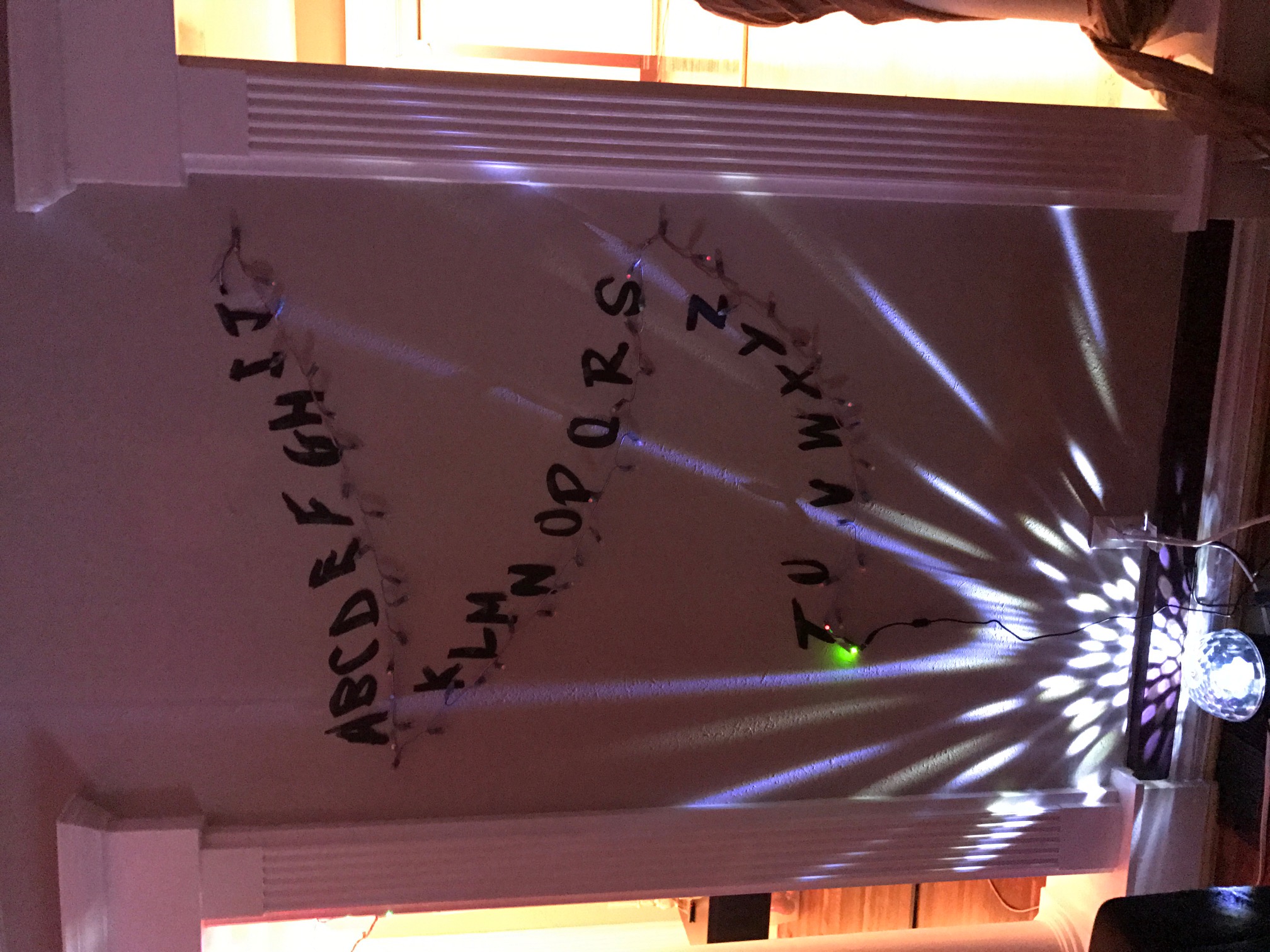
Yep, it said strange things. Mostly snarky political strange things.
They’re not terribly graceful, but they work. As far as I can tell, they’re just little circuit boards soldered together and stuck in a vaguely twinkle-light shaped mold:
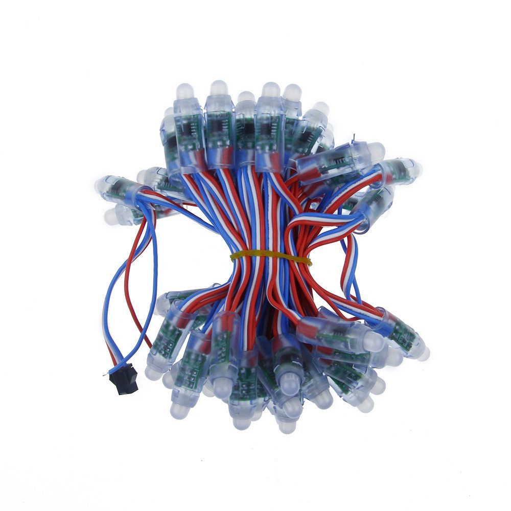
Anyway, Neo-pixel (or WS2811) LEDs are super easy to control. Not because the LEDs themselves are great but because there’s a huge amount of support available for them from maker-type communities. This particular strand accepts 5V, GND, and a data line and, with the help of some Arduino libraries, is able to illuminate each LED with 24 bits of RGB color.
These LEDs are meant to be daisy-chained together where they share power and ground rails and have a single-wire data line that goes from the output of one LED to the input of the next.
Unfortunately, there is a pretty substantial amount of impedance in these power busses, and once you connect two or three 50-bulb strands together, you can expect to see some voltage drop.
What’s fun about this voltage drop is that it actually shows up visually in the LEDs themselves. To generate white, you need red, green, and blue LEDs. Green and Blue LEDs generally need about 3.3V while red only needs 1.9. So when you try to display white on all 250 LEDs, you get this:
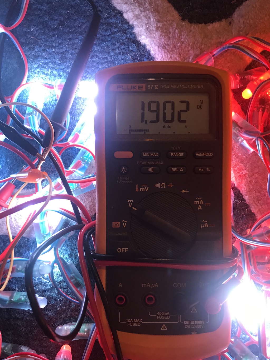
Fortunately, the LED makers anticipate this problem, so each end of the 50-bulb strand has some loose 5V and GND wires you can solder to a beefier power connection. I used some thick speaker wire to add power taps to the end of the 250 bulb strand and somewhere in the middle.
Though I still had to cap my brightness at 50% for full-white since my power supply only provides 5A.
Software
This is where the project gets mildly complicated. The software portion of this project can be split into three functions: LED Control, Mapping, and Display
LED Control
The Arduino is pretty dumb. It pretty much just sits as a bridge between my Python script running on a host PC and the LEDs themselves.
Here, I’m accepting 750 bytes over the serial bus (representing red, green, and blue values for 250 LEDs) and pumping them out to the NeoPixel LEDs. The Neopixel library accepts a single 24 bit number for each LED:
void loop() {
 for(uint16_t i=0; i<strip.numPixels(); i++) {
   strip.setPixelColor(i, 0);
 }
 for (uint8_t i=0;i<250;i++) {
   uint32_t col = 0;
   for (uint8_t j=0; j<3; j++) {
     col =col << 8;
     while (Serial.available() == 0);
     col |= ((uint8_t) Serial.read());
   }
 strip.setPixelColor(i, col);
 }
strip.show();
}
The only other exciting thing about the Arduino code is that it had to operate at 460,800 baud in order to keep up the LEDs at a reasonable frame rate.
Mapping
In order to make fun animations on the LEDs, we need to know the exact location of each LED. With the MPC Renaissance, I started with a picture of the device and wrote a script that would record where I clicked on that picture. By clicking on the LEDs in the order they were addressed in software, I essentially mapped the LED software address to their physical locations.
We’re in 2017 now though and everything is supposed to be solved with computer vision (or neural nets).
There’s a great open source project called OpenCV (Open Computer Vision) which has a bunch of awesome tools for giving robots eyeballs and letting them do the boring work for you like read license plates.
As someone who is terrible at software and can only really write in C and Python, this was surprisingly not scary to set up. Once you get all the necessary libraries installed, you can hook up a webcam and start working with images.
This little routine captures an image, converts it to greyscale, locates the brightest spot on that image, records the spot, draws a locating dot on the original image, and saves it on the hard drive:
camera_capture = get_image()
gray = cv2.cvtColor(camera_capture, cv2.COLOR_BGR2GRAY)
(minVal, maxVal, minLoc, maxLoc) = cv2.minMaxLoc(gray)
cv2.circle(camera_capture,(maxLoc),10,(0,255,0),-1)
file = "images\image"+str(i)+".png"
cv2.imwrite(file, camera_capture)
In order to map every LED to a physical location, all I needed to do is light up each LED in turn and run this routine.
Ideally, this would look like this:
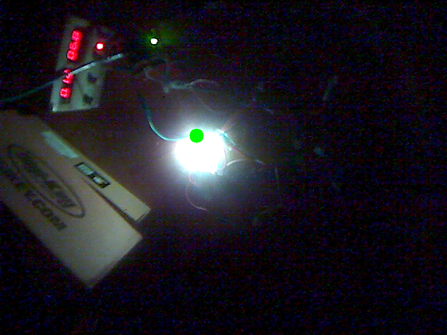
But because the cv2.minMaxLoc() function grabs the absolute brightest single pixel in the image, it is extremely susceptible to noise. I often ended up with this kind of result:
Where the LED on my power supply overpowered the target LED.
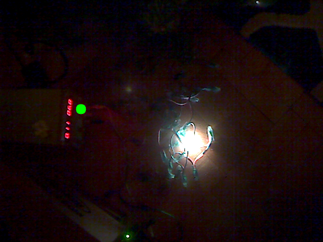
In order to improve the results, I applied a Gaussian blur with:
gray = cv2.GaussianBlur(gray, (19,19),0)
A Gaussian blur effectively averages each pixel’s value with the values of the pixels around it. Consequently, a single super bright pixel will be mellowed out while a large grouping of bright pixels will average together to produce the new brightest pixel. Using this method, I had few errors in pixel mapping. The X and Y pixel coordinates of each LED were stored in an array for later use.
colormap = [(26, 212), (309, 470), (304, 462),....
What’s fun about the pixel mapping is that it doesn’t necessarily have to map to the location of the physical LED. It only needs to map to the brightest spot produced by the LED. I found in a lot of situations that the LEDs tucked farther into the tree had no line-of-sight to the camera, so the software grabbed a portion of the tree illuminated by the LED instead. Because our animations will be playing back in exactly the manner they were recorded, this is fine.
Display
Once the LEDs were mapped, I was left with an array of their locations in the image frame. Graphically, this would look something like this:
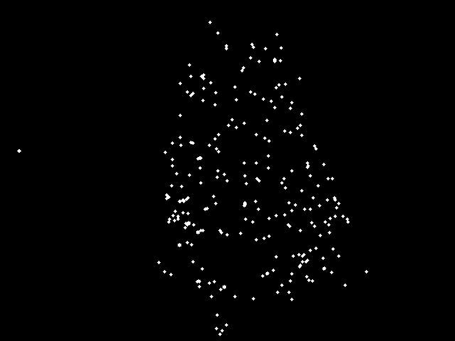
That little guy? I wouldn’t worry about that little guy…
With this map, all the software needed to do is lay the map over the image:
 And then sample the image’s color in each location. The end result is here:

Or in Python:
file = "giftbox.png"
giftimage = cv2.imread(file, cv2.IMREAD_COLOR)
for i in range(len(colormap)):
  tmp = giftimage[colormap[i][1],colormap[i][0]]
  colors[i] = [tmp[1],tmp[2],tmp[0]]
printcolors(colors)
Ta da! As you can see, it works best with simpler images.
Animation
One thing I noticed earlier on is that animations work best when they’re anti-aliased. Aliasing is most familiar when referring to trying to represent non-square objects on a screen with square pixels. In the below image, the top line has been anti-aliased and looks smooth while the bottom line sticks rigidly to the pixel grid:
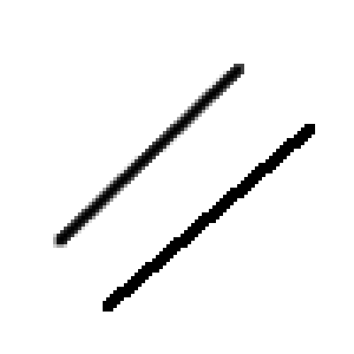
What I found was that when I was displaying images that did not adhere to a Christmas-tree-shaped pixel array (which is to say, anything), it was difficult to make out shapes.
This was most readily apparent when doing the scrolling text effect. With no anti-aliasing, the LEDs went from off to full bright as the text went by. This jagged animation was disorienting and made it difficult to make out the text.
By first blurring the image or “anti-aliasing” it, I was able to make the motion more gradual, and I found that it made it a lot easier to recognize the letter shapes and “connect the dots” so to speak for the dark portions of the tree.
Image Animations
I wrote a few scripts like one that would scroll the image from left to right:
while(1):
  if j<4490:
    j+=4
  else:
    j=0
  for i in range(len(colormap)):
    tmp = myimage[colormap[i][1],colormap[i][0]+j]
    colors[i] = [tmp[1],tmp[2],tmp[0]]
  printcolors(colors)
  time.sleep(.009)
Or one that would move the colormap around the image in a circle:
while(1):
  if j<1000:
    j+=1
  else:
    j=0
  for i in range(len(colormap)):
      tmp = myimage[colormap[i][1]+240+int(240*math.sin(j*2*math.pi/1000)),colormap[i][0]+320+int(320*math.cos(j*2*math.pi/1000))]
      colors[i] = [tmp[1]/2,tmp[2]/2,tmp[0]/2]
  printcolors(colors)
  time.sleep(.015)
I used this to do the color stripes animation with this image:
The time.sleep() command you see is to allow time for the previous frame to make it to the LEDs before sending the next. Poor-man’s flow control.
I was even able to use the webcam itself as a source:
while(1):
  camera_capture = get_image()
  for i in range(len(colormap)):
    tmp=camera_capture[colormap[i][1],colormap[i][0]]
    colors[i] = [tmp[1],tmp[2],tmp[0]]
  printcolors(colors)
The effect wasn’t that amazing though since the video source was so analog and offered little contrast. I could see major shapes on the tree if I waved my hand in front of the camera, but not much else. It also didn’t help that the camera’s auto gain settings were constantly adjusting the brightness of the tree.
Doom
So there’s this whole thing online about getting Doom to run on things like an iPod Nano or a graphing calculator, so I thought it’d be fun to try to get Doom to run on a Christmas tree!
Obviously, the tree itself won’t be running Doom, but Doom’s colorful graphics, low resolution, and name recognition made it a great target for my tree.
For the video, I used Freedoom.
In order to get Doom to show up on the tree, I wrote a script that would take a 640×480 pixel portion of my computer’s display (starting 500 pixels from the top and left of the screen) and use that as a video source for my tree.
while(1):
  img = ImageGrab.grab(bbox=(500,500,1140,980))
  img_np = np.array(img)
  frame = cv2.cvtColor(img_np, cv2.COLOR_BGR2RGB)
  frame = cv2.GaussianBlur(frame, (5,5),0)
  for i in range(len(colormap)):
    tmp=frame[colormap[i][1],colormap[i][0]]
    colors[i] = [tmp[1]/2,tmp[2]/2,tmp[0]/2]
    printcolors(colors)
If you think taking screen grabs for an input video source is inefficient, you’d be right. This script only ran at about 2fps on my top of the line 2012 iMac. I ended up having to run it on my VR gaming PC to get a respectable frame rate. This is probably the first time outside of gaming that that Mac has felt slow 🙁
Anyone, if anyone knows a real way to do this that doesn’t involve screen grabs, let me know.
Conclusion
So yes, this is really just a proof of concept, but I think it has legs as a really great consumer device.
The way I see it working is with some sort of bluetooth box on the LED strand and a smartphone app. Pair the box to the phone, string the lights, aim the phone’s camera at the box, and stand back.
Then of course you could download a huge library of animations, draw on the tree with a paint application, play Tetris, whatever you want.
Didn’t have time to do all that this time around though. Maybe next year!
Pingback: Using Computer Vision to Play ‘DOOM’ on Spatially-Mapped Christmas Tree LEDs | #doomgame #OpenCV @DOOM « Adafruit Industries – Makers, hackers, artists, designers and engineers!
I believe these guys already beat you to the punch. Though they have a very buggy app so there’s still a big market hole. https://www.twinkly.com/how-it-works/
Beth just viewed your profile! Click here: http://inx.lv/GkWu?h=b534cecbec0c6fbc65fce74dba533186-
odvy9p
73krbh
ilwqbk
60xpe0
ls9wr3
3htydw
f36k3h
ogfmtt
csvzes
cnvttd
sh11kn
5418sr
1w20lu
jjj9dr
z9yxvr
9kq5e8
tc8sbh
97be5x
mit4gi
jqailo
fguph2
bhoh30
ybf1n1
0r3up3
rkdgnh
pq8kdp
ncvi7q
4ozxfs
qop2nt
qp4xnv
s5dp9g
rf1c0w
i5gr6t
maj99d
22l5qc
j92pws
0zniim
1imwyv
dmdecs
exvns0
04dd7h
ou3a1k
qdlplg
uvmcj6
fv3xj0
g1keos