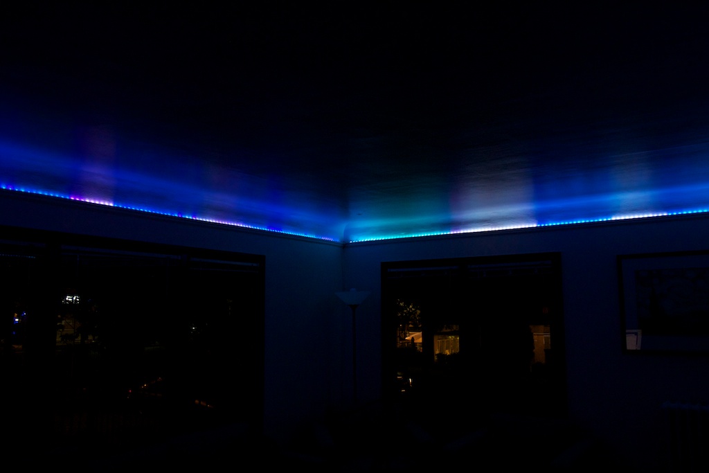
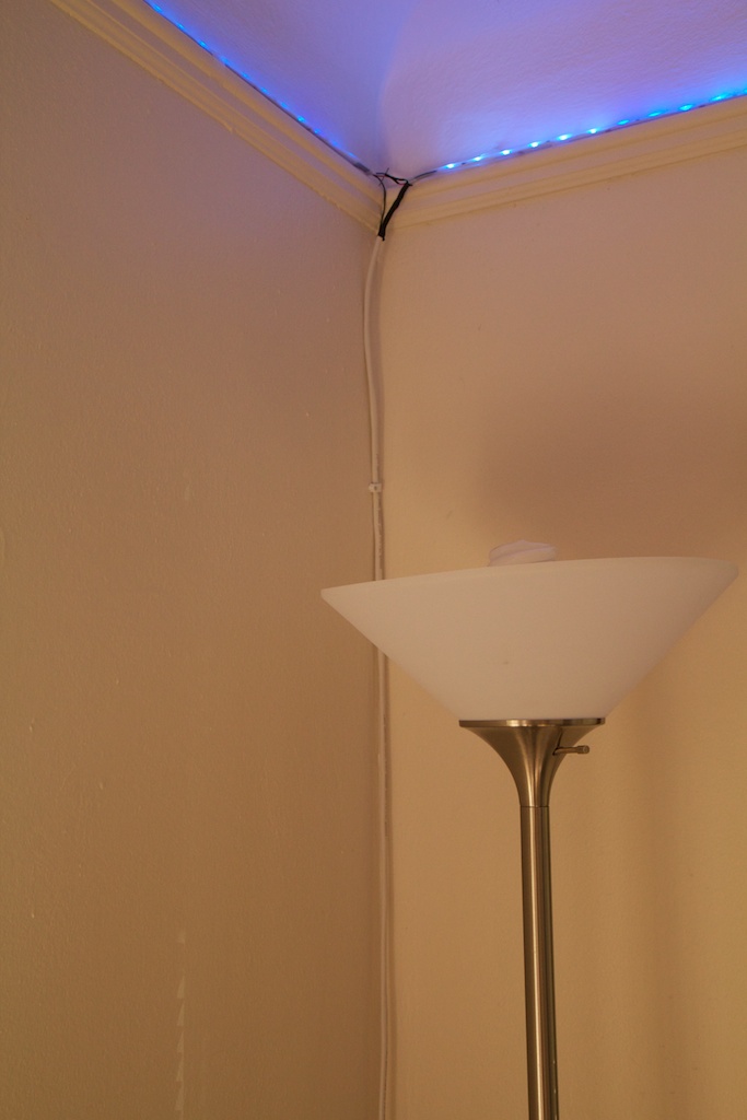
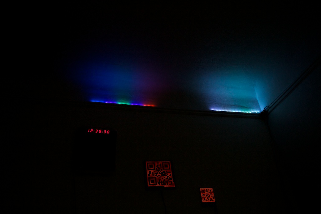
So this looks kind of pretty I guess, but it took a lot to get here.
Unbucking it
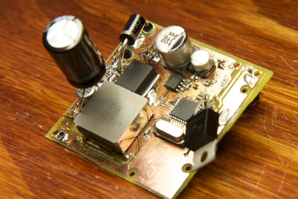
If you remember from last time, I made a few mistakes when planning out the power supply for my new fancy party lights. Namely, I chose the wrong kind of diode and capacitor. I’m proud to say that after that debacle, I managed to get a very steady 12V out of my buck converter using the new components:
The new diode is rated for 100V and 5A, and the capacitor is rated for 1.49A of ripple current with a 38m
![]()
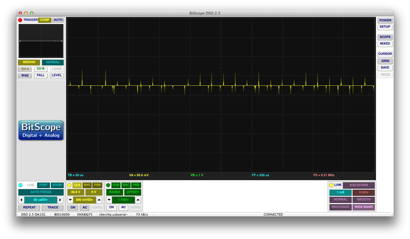
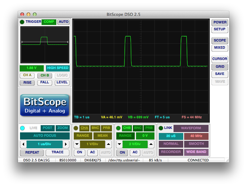
ESR. With these guys in place, the voltage ripple of my output dropped from a whopping 1.35Vp-p to well…almost nothing:
And here you can see it powering and controlling the LEDs:
Regardless, fixing this power supply was only an exercise in demonstrating what was possible. The supply can’t keep up with more than one strand of lights, so I decided to strip everything off and just use it as a controller with a separate 12V power supply powering the lights.
Besides, while it was no longer getting super hot, it was still getting warm enough to make me uncomfortable leaving it on for extended periods of time stapled to my ceiling…
The LEDs
Before getting into all the details of the stuff I further messed up in this project (there is a lot), I think it’s important to layout the fundamentals behind how it was supposed to work to give everything context.
The Dreamcolor LED strands that I purchased run off 12VDC and draw about 1.8A a per 5 meter strand when powered on all the way. They have four connections on each side: two for data and two for power:
The pins are configured so they can be daisy chained together. The power rails are just a straight through connection from section to section (so all sections are running in parallel), but the data pins actually enter and exit the onboard ICs.
These ICs are the LPD6803 which it turns out are like the end-all of large-scale serial LED control. Using a special protocol, these ICs strip the data they need from the incoming signal and pass the rest through. They contain integrated PWM drivers which maintain the RGB LEDs at independent fixed brightness levels even in the absence of incoming data. There are 5 bits reserved for each channel meaning that each color can be driven at 32 different brightness levels (including “off”) allowing for 32,768 possible colors.
Neater still, they can drive LEDs with a rail up to 12V, but only need a 5V signal for data and clock. Seems like a great way to do it.
The LED protocol
The serial protocol is a little weird and not very well described in the data sheet:
I think they accidentally a few words there.
Here’s what I was able to figure out:
- Every new frame must begin by clocking in 32 zeros (clock on rising edge). Presumably this just tells the system that you’re going to be starting fresh.
- Begin clocking in pixels. Each pixel begins with a one which is followed by 5 bits for red, 5 bits for green, and 5 bits for blue.
- When all of your pixels are clocked in, clock in a zero for every pixel you just sent.
There are a few interesting things about this protocol. Because they’re all daisy chained together, each driver IC presumably must see and then generate a signal that looks something like the signal the controller sends to the first driver.
My theory is that the 32 zeros must reset the IC and cause it to pass 32 zeros to the next device. Once reset, the device will store the first RGB values it receives and pass all the rest along.
I’m not too certain what the final zeros are supposed to do. At first, I thought they were some kind of latching signal to tell the drivers to change their LEDs to the newly programmed values, but in my testing, I think I remember seeing the LED drivers changing their LEDs before I sent this signal out. When it’s working correctly, sending data to the LEDs is so fast, there isn’t really a need for a latch.
It would explain why every frame must start with a 1. Perhaps when they get a frame that starts with a zero, they know to latch their values to the LEDs and pass the following zeros on. Though in that case, I don’t know the significance of the 32 starting zeros…
Regardless, I was too lazy to dig into it further (mostly because the LEDs I bought are encased in a waterproof rubber sleeve which makes probing difficult), so I just programmed device to send the signal as described.
Update
As Ken pointed out in the comments section, the final set of zeros are required to get the last bit of data input to the end of the strand. This strand operates as a sort of “reverse” shift register. The first data input stays at the beginning of the strand and the last data input goes to the end. Once the drivers latch their color data, they pass the remaining data along, but they do so by buffering a single bit and passing it on the next clock cycle (otherwise they would need some kind of asynchronous system). In order for the last bits of data input to make it all the way to the end, they need a single clock pulse for each driver to move the stored bits all the way to the end.
The serial protocol
Originally, I was a little concerned with how long all of this was going to take, so I built my driver with two outputs. The plan was to have the driver board send data to two separate sections of LEDs. This would effectively double the data rate.
Of course, had I done a little math before starting, I wouldn’t have thought this. The maximum data rate I can pass through the FTDI serial adapter I’m using is 230.4kbps. Since the device wants 5 bits each for red, green, and blue, I had to decide how I was going to send this over an 8 bit serial bus.
I ended up coming up with a pretty straight forward protocol. The lower 5 bits of each byte sent contain data for a single color which alternates each time a byte is sent. Every 3 bytes represents a single RGB pixel of the output. The controller will capture and store these values in a frame buffer as they are sent.
The upper two bits can be set to command the controller to do something specific. The 8th bit is reserved for telling the controller that it’s time to output the currently stored frame to the LEDs. The 7th bit tells the device to dump the frame buffer and start over (in case data gets corrupted somewhere along the way). I haven’t found anything to do with the 6th bit yet.
So, 170 some pixels with 3 colors each comes out to around 510 bytes or 4080 bits of data per frame which when sent at 230.4kbps will take 18ms to arrive. This is much, much slower than the output of my microcontroller running at 11MHz. I measured my data clock pin at somewhere around 660kHz. Considering that it doesn’t have the reserved control bytes to worry about, even with the added start and stop zeros, it can still dump an entire frame in about 4ms.
Now 4ms isn’t zero, so it still needs time after every frame is sent to display it to the LEDs which means my minimum time between frames is 18+4ms or around 45 frames per second. I could probably improve this by programming in some kind of circular frame buffer that could be read from and written to simultaneously, but 45fps is still faster than conventional television, so I’m sticking with it.
Power
The LED strips were shipped in packaging that warned against running more than 5 meters in series. Presumably, the concern is with large amounts of current traveling long distances over the thin conductors in the LED strands.
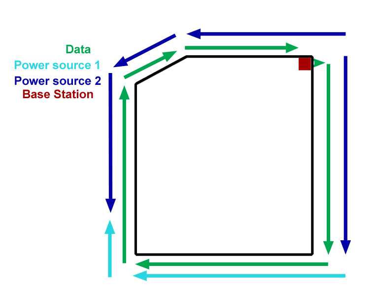
Fortunately, my room is laid out in a way that makes it easy to have all of the strands powered individually. What’s cool about their configuration is that while data must come from one side, power can come from either side as all of the sections are running in parallel off the same power rails. I ended up configuring the room like this:
As long as all of the lines share a ground connection, they can take power from two sources such as the top right and bottom right of the above diagram while still only taking data from the base station.
Getting power up to the ceiling was achieved with some heavy duty speaker wire:
Which I spliced into my power supply.
So what went wrong?
Oh boy, where to begin… This whole mess spanned over the course of a week, and to be honest, I forgot the order in which a lot of things happened, so I’m just going to lay out what I remember.
I think I legitimately made a mistake or had a major problem along every step of the way. It’s especially hilarious considering this was supposed to be a quick and easy project.
Bad power supply
Moving away from the buck converter, I needed a good 12VDC power source to run the lights. I already had a 4A supply powering “source 1” above, but I wanted something beefier for source 2. At first, I was using my lab power supply, but I wanted something that wouldn’t tie up such a valuable resource I settled on a 12V, 6A DC power brick which I found on Amazon for  100 (even the Amazon lists the “original” price at $260), but for some reason, this is like the sale of the century and I got it for scarcely more than I paid for the original strands:
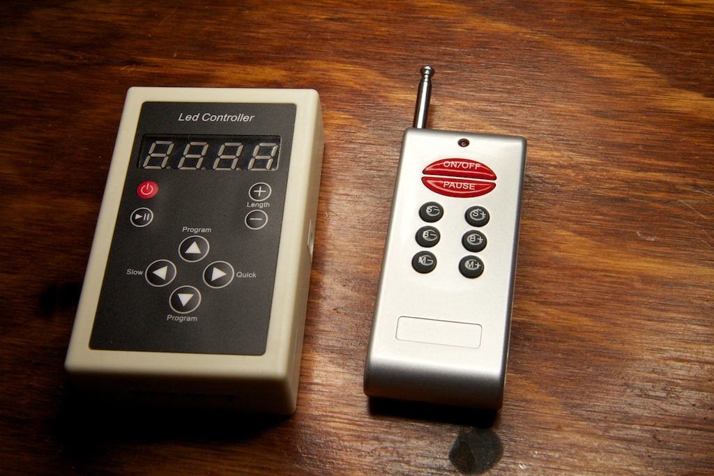
In a pinch, the controller’s actually pretty cool. It has a few hundred different patterns pre-programmed (though a lot of them are the same pattern in a different color), and the remote control can change the pattern or the speed. The remote also uses radio instead of IR, so you don’t need a line of sight to control it.
I might hook this thing up to my leftover LED strands and glue them to my bike or something…
Anustart
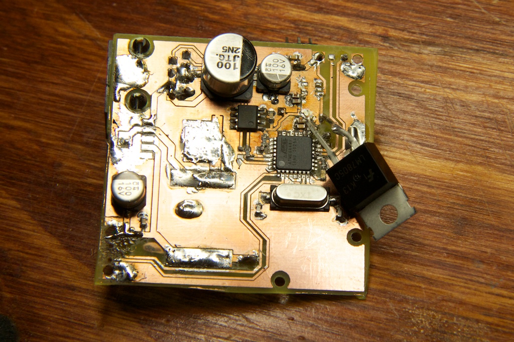
After proving that the buck converter worked, I quickly set about ripping all of the buck converter parts off to be stored for perhaps a later project. I unfortunately blew up my surface mount 5V regulator due to some nasty solder shorts, so I had to replace it. I blew that one up too and didn’t have any more extra, so I opted for an LM7805 in the TO-220 package:
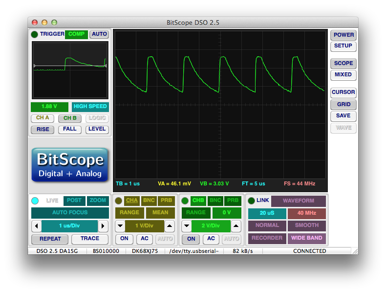
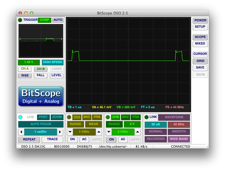
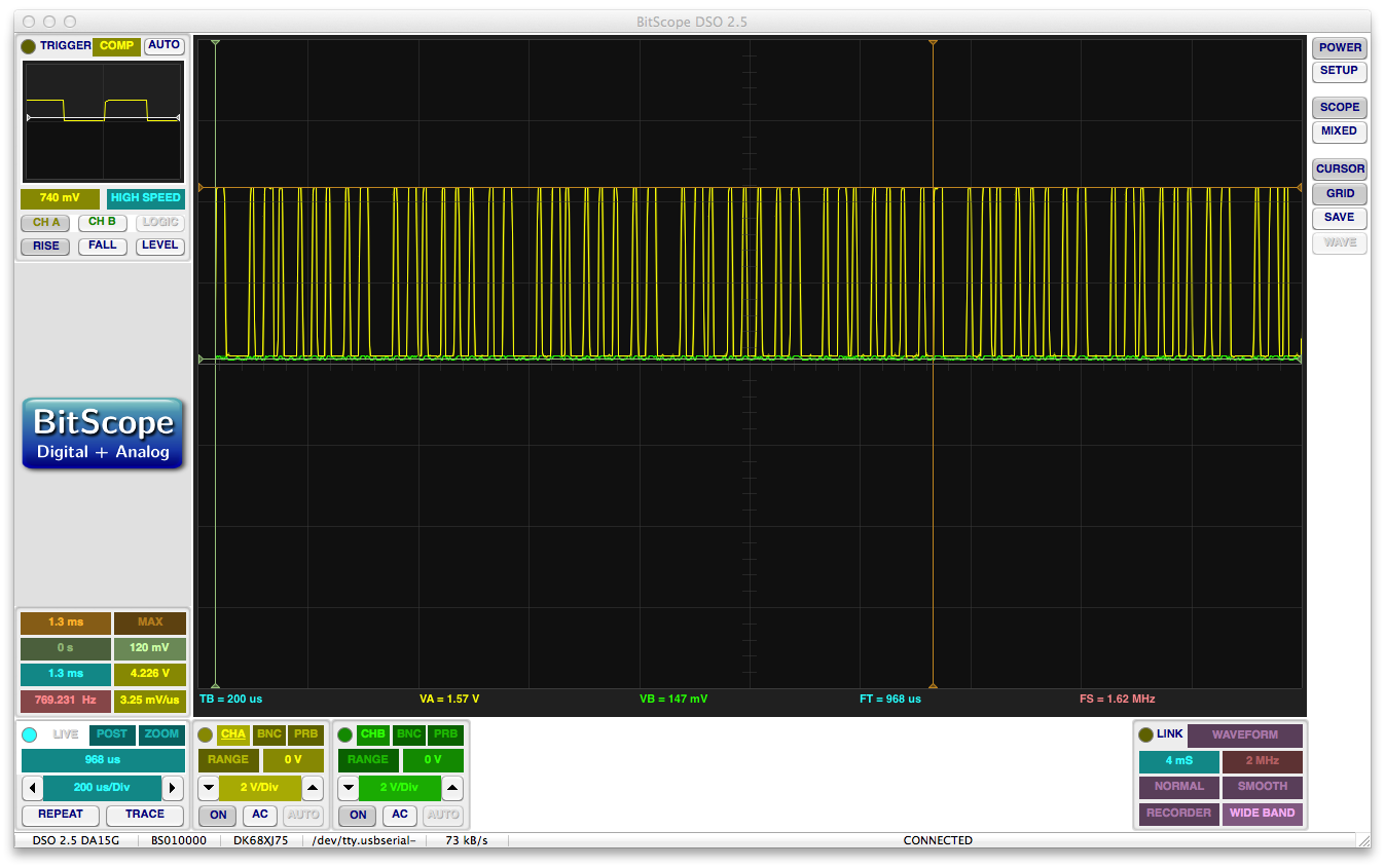
Strangely, after making these changes, the controller stopped working. With some poking around, I noticed that something was wrong with the clock pin. It wasn’t pulling down hard enough and the output wasn’t looking very square:
This pin was on the same port as an indicator LED that was working fine, and after looking around for a while, I established that the problem was localized to that pin. I tried swapping out the microcontroller, but due to some nasty soldering, I ended up blowing that one up and another after it (alcohol may have been involved). The board was looking pretty haggard, so I decided to give it a rest and start fresh in the morning:
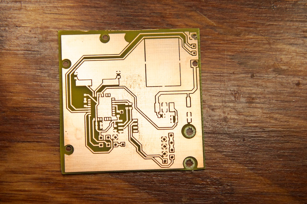
This new revision removed the buck converter and replaced it with a footprint for the 7805 that was so haphazardly soldered before.
Nogrammer
Unfortunately, when I soldered everything down, I somehow mixed up a 7805 and a 7809. So powering up the board sent 9V coursing through my circuit. You’d think they’d label these things or something!
Oh…
As you can see above, I did eventually swap in the LM7805, but not before I already (presumably) blew up (yet another) microcontroller that needed to be replaced. I say “presumably” because before I had a chance to program it, I had another problem. I only discovered this problem after connecting my AVRISPMKII programmer and watching the current output on my power supply rise to 1.5A.
After this point, the programmer would only blink the LED orange which would normally indicate that the programming header is backwards, but in this case indicated that the programmer was borked seeing how that’s all it would do on any of the devices I connected it to.
This isn’t the first programmer I’ve obliterated.
So great, it’s 11AM on a Saturday, and I had planned to spend the whole weekend on this project. Although my firmware is pretty much finished, and I only need to write it to the microcontroller, my programmer is dead, and I won’t be able to get another one until it gets delivered from Digi-key. That’s like 2 days at the earliest.
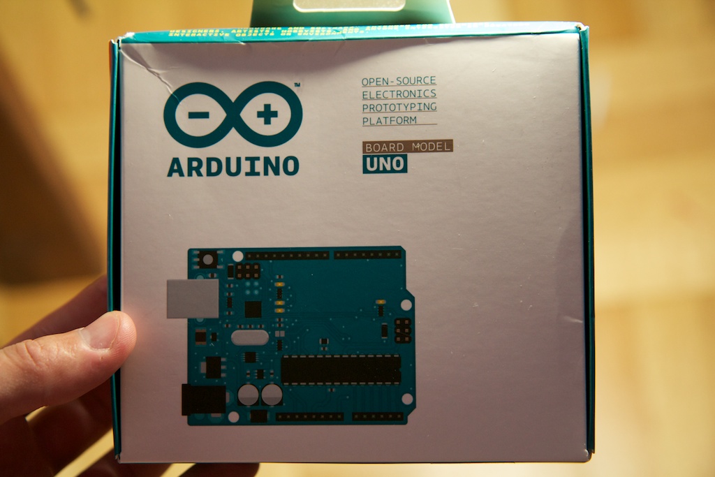
Desperate, I did something I never thought I’d do in a million years. I bought one of these:
I’ll have to post a rant about why I hate Arduinos at some point in the future, but a lot of it could be summed up in this comment I received the other day:
So why did I buy this thing? As it turns out, Arduinos can be programmed to emulate AVRISP programmers. It also turns out that they’re available for purchase at Radio Shack. It also turns out that Radio Shack is open at 11AM on a Saturday morning.
Despite this fortuitous stop gap saving me a ton of time waiting, it still took me three hours to get it working. The programmer emulation features of the Arduino aren’t amazingly well documented.
Installing the emulation software (sorry, I meant “sketc-” *gag*) was pretty easy. It’s included under the “Examples” section under “ArduinoISP”. What isn’t as straight forward is getting AVRdude to recognize it. I had to add these flags to the Makefile:
-c avrisp -P /dev/tty.usbmodemfd1331 -b19200 -v -v -v -v.
The ‘-v’s are for mega verbose mode which helped in debugging. The “avrisp” is changed from “avrispmkii” because presumably this emulates an earlier version of the device. The /dev/tty.usbmodemfd1331 is the name of the Arduino’s serial interface in OSX. It’ll vary from computer to computer. The hardest part to figure out was the -b19200. This specifies the baudrate for communicating with the programmer. This was super difficult because AVRdude wasn’t throwing any kind of flag indicating that it couldn’t talk to the programmer. Finally, with everything set, it worked.
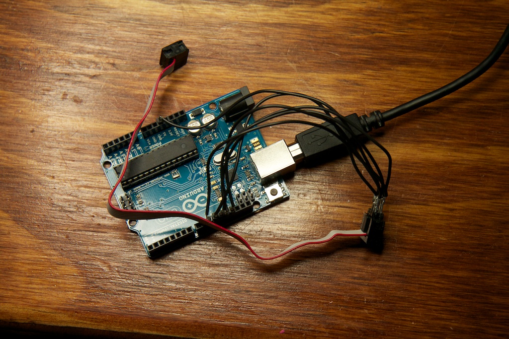
The hardware was pretty straightforward. The comments at the top of the ArduinoISP code indicate which connections need to be made. I combined the broken programmer’s cable with a header I usually use for breadboarding and came up with this:
Of course, this thing doesn’t have the specialized hardware that the normal programmer has, so it won’t indicate when the header is connected backwards. It also doesn’t have any level changers, so it can only be used to program 5V circuits.
To make things easier, I powered the target board from the 5V pin on the header during programming.
So with that all working, I was back in business.
Bad input
Somewhere after that debacle, I began to have problems controlling the LEDs again. I started noticing the messed up clock trace again, and this was on this entirely new PCB. In fact, the messed up clock trace I showed above was actually taken at this point, but it looked exactly like the original which I didn’t think to keep.
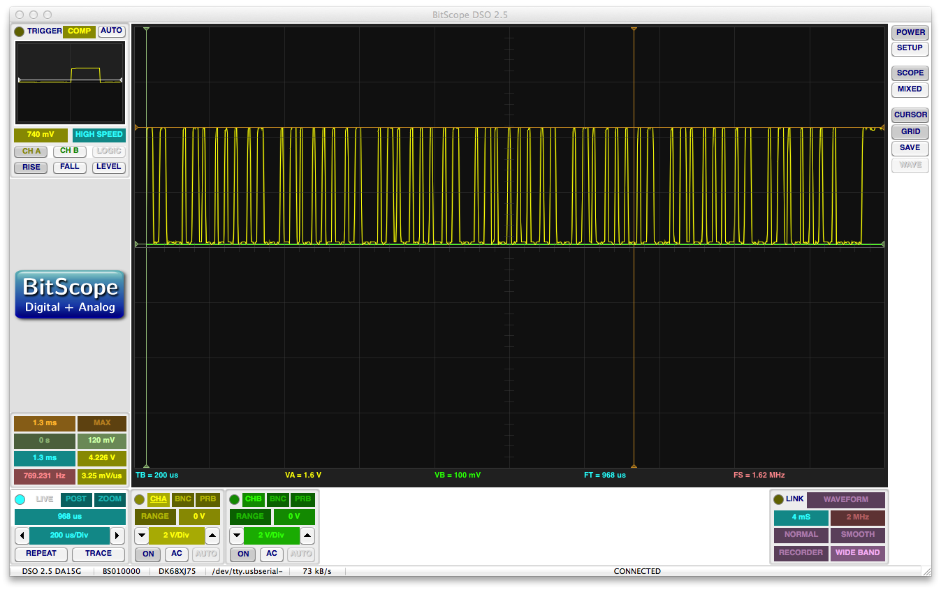
This time the data line was also acting weird. Here’s the data line with the light strand connected:
And here it is with the light strand removed:
It looked like there was some kind of intense pulldown behavior on the data line. I postulated that perhaps something similar had happened on the clock line which caused it to eventually damage the output driver of the pin.
Disconnecting the lights and measuring the data and clock inputs didn’t reveal anything useful. They each had 20-30k
![]()
of resistance to ground which is more than high enough to drive with a microcontroller.
Regardless, the problem persisted when I reconnected the lights. Guessing that this problem was unique to this particular segment of lights, I sliced off the first section of LEDs and connected the controller directly to the second section. Voila! Problem solved.
The problem also came up on the first section of my third strand. What was so weird about this is that these strands were all working at some point and then broke. I decided to take a closer look.
In order for the LPD6803 to operate, it needs a 5V VCC line. The chip doesn’t really do anything with the 12V, it’s just that the LED pins are 12V tolerant. For everything else, it needs 5V just like a normal micro controller.
Adding a 5V line to go along with 12V and data would be clumsy, and linear voltage regulators are expensive and bulky, so the designer of the Dreamcolor LEDs did it a different way.
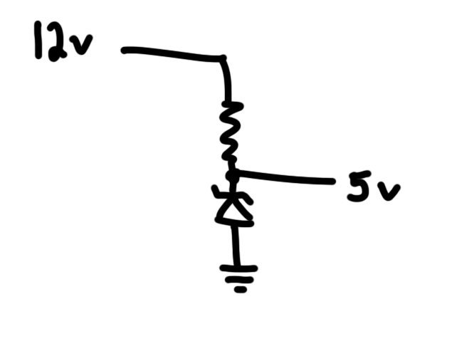
This is probably the most straight forward voltage regulating power supply you can make. The schematic looks something like this:
The diode here isn’t a normal diode. It’s a special kind of diode called a Zener diode. Zener diodes are special in that they block reverse current until a voltage is applied to them greater than their threshold voltage. Once their threshold is met, they will allow current to pass with little resistance. You can select the specific threshold voltage when ordering. In this case, it’s 5V.
So the idea here is that when you supply 12V to the top, current will flow through the resistor and diode. Because the diode has a 5V threshold voltage, it will pass enough current such that the drop through the resistor is 7V (12-5). This is not unlike choosing a current limiting resistor for an LED.
When you apply a load on the 5V rail, more current will flow through the resistor. This will cause the resistor’s voltage drop to increase lowering the 5V rail. This sag in voltage will lower the rail below the threshold of the Zener shutting it off. With the Zener shut off, less current will flow through the resistor causing the rail to rise again eventually settling on 5V.
This process was spelled out to aid in explanation, but in reality, it all happens instantaneously and the 5V rail stays locked steady at 5V.
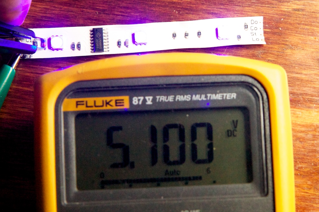
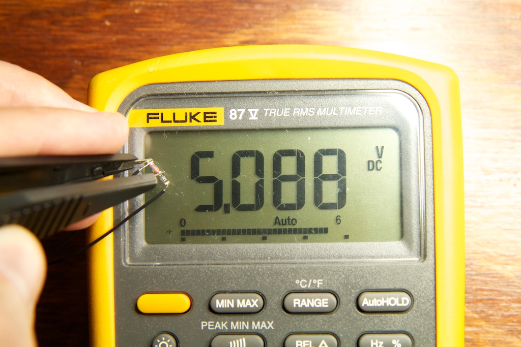
Measuring the voltage across the diode on a working section of LEDs, I found this:
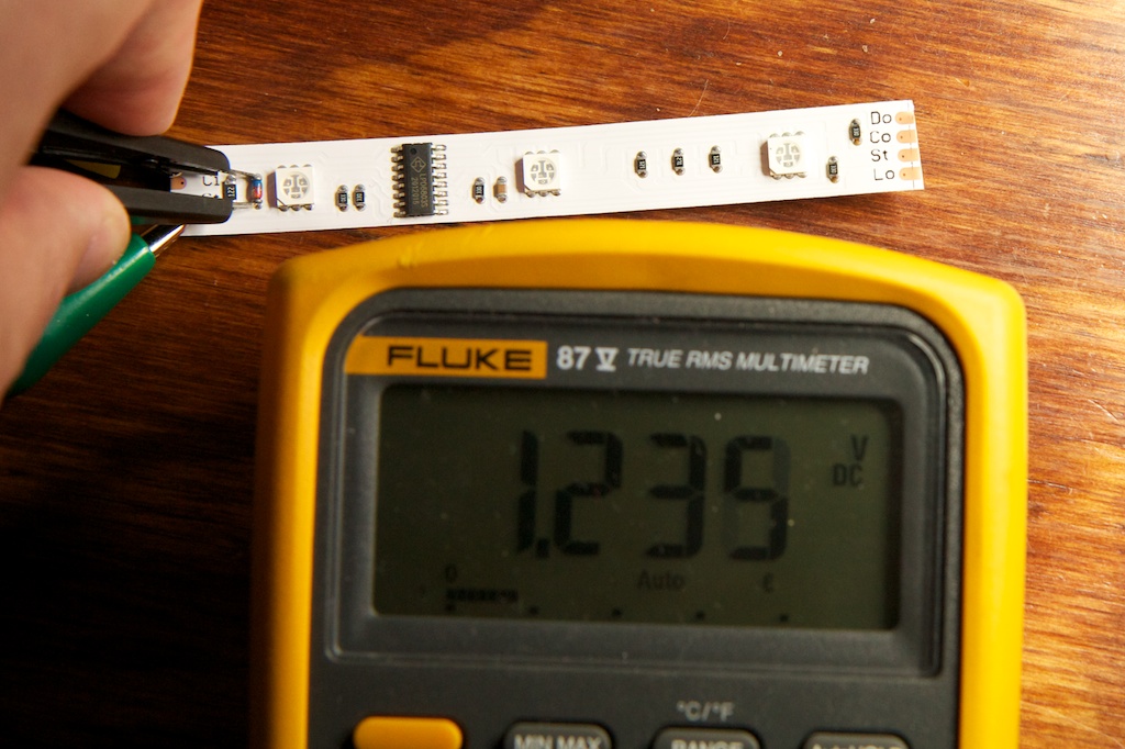
But measuring on a broken section, I got this:
So there’s your problem!
My first thought was that the Zener diode was somehow broken. To check for this, I took it and the resistor out of the circuit, and set up my own little regulator:
Whelp, that’s not the problem… So what’s going on here?
You might have suspected that there are some limitations to what you can do with Zener diode voltage regulators. Otherwise, you’d see them a lot more often. Besides the fact that they’re highly inefficient, they also have a very limited range of output current.
See, at some point, the load placed on the rail will draw more current than the Zener did at the beginning. After this point, even if the Zener shuts off all the way, there will still be enough current flowing through the resistor to droop the voltage below 5V.
In this case, the 1.2k
![]()
resistor can pass up to 5.8mA before there’s a problem (5.8mA*1200
![]()
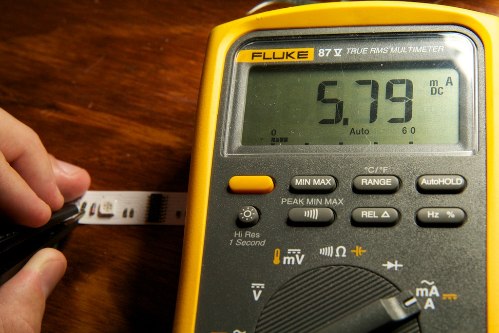
=12V-5V). Doing a quick measurement of the current the chip is using on a working section gave me this:
Cutting it pretty close there, eh guys?
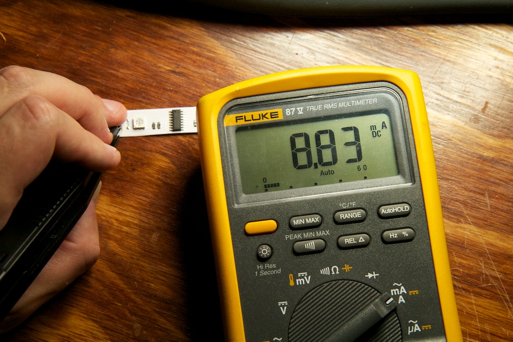
A similar measurement performed on a broken section:
And it’s pretty clear what’s going on here.
What I suspect was happening here is that some sort of “event” (ESD, electrical surge, whatever) broke the LPD6803 in the first segment of those strands. This failure mode included drawing a larger current somewhere which caused the 5V rail to droop down to 1.2V. As a part of this failure, whether caused by low voltage or something else, the data and clock inputs started drawing a lot of current. Repeated high current loads on the GPIO pins of the microcontroller caused those pins to eventually break giving me the crappy waveforms shown above.
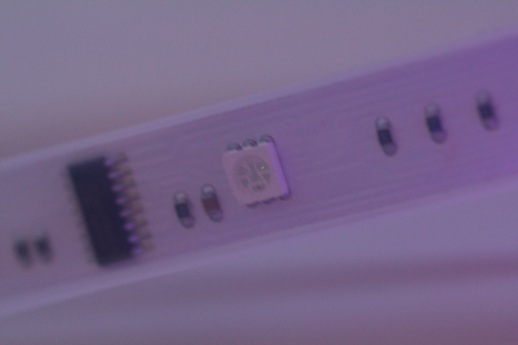
I probably should have figured this out when I noticed that the LEDs weren’t lighting up, but when the strips are first powered on, their LEDs are in an indeterminate state which can sometimes be totally off. It was only after closer inspection that I saw this and knew something was up:
The LEDs definitely aren’t supposed to get that dim.
A new strand of LEDs still left me with a broken pin on my microcontroller, and rather than swapping it out (yet again), I decided to just do some rework to use a different GPIO pin. I picked one of the programming pins as it was easier to solder to the programming header:
PySerial
So with all my hardware in place, I needed to write a Python script to drive patterns to the LED controller over the serial port on the FTDI chip. I had a really hard time getting this to work as I found that every few signals sent, there’d be a totally corrupt frame that would flash all of the LEDs a different color.
Suspecting just about everything at this point, I eventually settled on probing the serial output of the FTDI chip and was fortunate enough to catch something strange. Here is the beginning of a normal UART stream:
Every once in a while though (maybe once every two seconds), I’d get one of these:
It might be subtle, but you’ll notice that there are two little bumps at the beginning instead of one. It’s like it got one bit into a byte and decided to start over. At the time, I was invoking a Serial.write() command for each byte I sent from the Python script.
I think that doing it this way must be very inefficient for the Python backend. Perhaps it releases control of the serial driver between writes?
Fixing this problem was pretty simple. In addition to sending single bytes, Serial.write() is able to take an entire string and output it one byte at a time. This method appears to be much more efficient and got rid of the problem for me.
Insufficient memory
Excited about getting my final strand of LEDs, I installed them right away. This required a change to the firmware to increase the size of the frame buffer and an update to the Python script to increase the width of the pattern. Unfortunately (SURPRISE), all of my lights stopped working as soon as I adjusted the Python script to control an additional 20 some pixels. The colors only updated maybe once per second (if at all), and it never matched up with what I was sending.
Earlier, I had some problems with serial timing when I wasn’t allowing enough time between packets, so that was my first guess. Perhaps sending all of the bytes in a single Serial.write() command was overflowing some kind of buffer? I was also concerned that I had messed up the new firmware although it seemed to work fine with smaller frames.
After playing with the numbers a bunch, I found that as long as I sent 166 pixels or fewer, it worked fine. Well, maybe not super fine…
All of the LEDs were supposed to be black in the above image. The section on the right is the LEDs past 166 which I can’t try to control without crashing the controller. The LEDs in the middle appeared to be “stuck” on various colors. I was a little surprised to see this as I had just tested the strand earlier when I was playing with the LED controller from Amazon. Maybe I had stepped on them and broke something?
Because I had enough extra LEDs to replace this broken section, I didn’t think too much of it and focused instead on this 166 problem.
166 pixels at three bytes a piece with a frame clear message at the beginning and a print frame message at the end (using the 7th and 8th bits) came out to:
![]()
Well…that’s a strangely square number…
At this point, I really started to suspect Python. Normally, in the microcontroller world, numbers are powers of 2. Perhaps the PySerial library only allowed for 500 bytes in the serial buffer? a quantity arbitrary selected by a developer?
It was only after I gave up and went to work that my mind could wander enough to find the culprit.
For this project, I was using the ATMega48. The ATMega48 is a member of a series of pin compatible parts that have varying levels of onboard flash and RAM. The ATMega328 for example has 32k of flash and 2K of SRAM. The ATMega48 has 4k of flash and …512 bytes of SRAM.
With 170 LEDs, I needed 510 bytes of RAM, and I only had 512 to work with. The reason the code started acting funny when my frame grew longer than 166 pixels is that I was overwriting some other variable with LED data. In fact, the “broken” section of LEDs was actually some other random piece of system memory being read and interpreted as part of the framebuffer. How cool is that!
This problem really surprised me because I had marked just about all of my variables as “volatile” which means they have sections in memory specifically carved out just for them. I would expect that the compiler or linker or whatever would notice that there wasn’t enough RAM before it decided to allocate variables on top of each other.
Had I worked out the numbers a little bit ahead of time, I would have just used an ATMega328 which has more than enough RAM. This is not the first time I’ve done something like this.
If you read through that link, you’ll find this quote:
I guess it was sort of silly to do development work on a 4k part when the 32k equivalent was not much more expensive. I guess I’ve never really had a need for that much memory before. I’ll be sure to order larger parts in the future so I don’t run into this problem.
FUNNY.
Swapping in an ATMega328 fixed the problem. Though as an aside, I’d like to add that after checking every single solder joint for shorts and making sure I had everything connected right, I managed to do this:
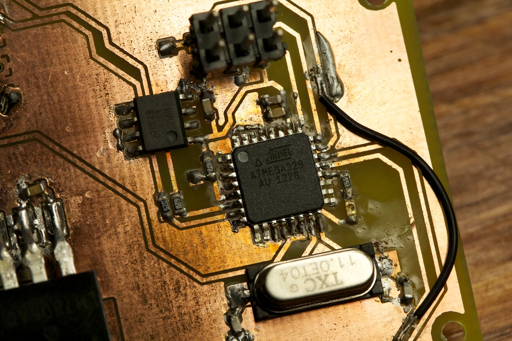
The chip is rotated 90 degrees from where it’s supposed to be. I’m really like 0 for 20 at this point…
With that fixed, the ENTIRE strip works excellently.
Things that I didn’t mess up, but still kind of suck
So, I’ve talked about color accuracy of LEDs before. When making LED displays like this, it’s important to match the LEDs perfectly so that they all agree on what each color should look like and guarantee a certain level of color consistency. When this isn’t possible, LED controllers can sometimes be programmed to calibrate the LED color and modify their output levels to keep colors more consistent between LEDs.
As it turns out, my LED strands disagree fundamentally on what certain colors look like. For example, here’s two interpretations of yellow:
Interestingly, although the color mixture is totally off for yellow, it’s not perceptible with pure colors such as red:
I’m guessing that human eyes (and therefore camera sensors) are less perceptive of slight changes in brightness than they are of slight changes in hue. Non primary colors such as yellow require accurate mixing of two colors. A slight miscalibration there will shoot the color off in a totally different direction.
So how do you fix this? One solution is to just limit your patterns to those that use primary colors. It was interesting to note that a majority of the patterns that came with the controller I purchased off Amazon used only pure red, green, and blue.
Another solution is to use the built-in color calibration functions of the LPD6803 outlined in the datasheet:
Not totally sure what they’re trying to say here, but I’m guessing that the LPD6803 has some sort of feature for setting the “gray level” which has a higher bit depth than the typical 5 bit control. Unfortunately, using this feature requires a few hardware changes, and I don’t have any control over the circuit the parts are already connected to.
The final option is to try to calibrate it in software. Unfortunately, I only have 32 shades of each color to work with, so I would have to severely limit my color depth in order to do this. I’d probably end up creating a list of possible colors and having to design patterns using only those.
I might take a stab at this in the future, but for the time being, I’m very pleased that I have it working, and I’m just going to leave it as-is.
So now what?
At the moment, I have 171 segments of individually controllable party lights attached to the ceiling of my apartment. They’re pretty dang sweet.
I had a friend help me write a quick script for generating patterns, but it barely scratches the surface of what these lights are capable of. I’m going to take a break from this project for the time being (for fear that I break something again), but I’ll be writing some pretty cool control software at some point in the future, so expect something cool soon.









The additional single clock per pixel suffix is due to reclocking the data at each IC. So once the IC’s taken the data it wants, it likely switches to clocking the data through a single D flip-flop FIFO and then back out the DOUT pin. (DIN clocked in by DCLK, DCLKO = buffered DCLK, DOUT clocked out by DCLKO)
That datasheet is horrendous. Your snippet from the page regarding
“SuperPWM” missed the GMODE=0 note on the line previous to your snippet. The way I take, and given the table on page 10/11, GMODE=0 applies a reverse gamma correction of 1.8 with a table conversion of values from 0 to 31 to 0 to 256. Curiously, the datasheet says that when GMODE=1 (linear), you only get a maximum output of 128/256 given an input of 31; odd. So, no, I don’t think there’s a way to send it an 8-bit value.
I didn’t see that you were using the SPI peripheral to send the data. Are you?
My suggestion:
0) Flexibility expansion: Given the LED driver IC’s will only reclock data that they don’t care about, you could route the data out from the last pixel back to your MCU to determine the number of pixels in the chain. As soon as you see a “1” come back, the chain is complete and you can determine how many there are.
1) Set up a process to dump an array from RAM out the SPI bus constantly. Or rather, from one of two arrays in memory.
2) Find the fastest you can send the data out via SPI. Datasheet suggests it can handle up to 15MHz, but then suggests limit it to 2MHz for a distance of 6 meters. I’m guessing that’s for the driver from their IC; not any sort of host. YMMV.
3) It you can get an adequate “frame rate” for your given number of pixels, introduce your own interpolation process to correct per-pixel issues. This is only possible if you can get an adequate refresh rate that the interpolation flicker wouldn’t be as noticeable. You would also need to be able to calculate the interpolation for each pixel in a single frame in order to fill the buffer that’s not currently being sent before it needs to be sent.
4) Rework your serial protocol since it’s no longer tied directly to your output.
– Add the ability to define how each pixel will be “corrected”. Be it a table expansion or otherwise.
– Add a command for single pixel setting. (as well as full array)
– Add command to return number of pixels detected.
Oh duh, of course! I was thinking it was like a conventional shift register where the first data input ends up at the end, but with this “reverse” system, it needs some extra clocks to make sure it makes it all the way there.
I’ve actually never used the SPI peripheral before. Looking at the data sheet, it looks like it has a maximum speed of Fosc/2, so presumably, I can get it up to 6MHz which is potentially 1,000x faster than my current bitbanged setup. I was initially wary of using it since it sends a byte at a time, but with some clever bit combining and some rounding up to the nearest byte, I suppose it could work. I’ll give it a shot (of course, this would be a lot easier if it wasn’t currently stapled to my ceiling).
0) Neat idea! If I ever release a consumer version of this thing, I’ll definitely add that.
1) This would be pretty trivial. I just need to change the function that tells it to stop at the end of the loop and move the whole chunk out of the serial byte received interrupt and into the main loop or a timer interrupt. I’ll need to work out the math to make sure it can maintain a consistent framerate as the rate of incoming data changes.
2) Datasheet says 6MHz, but I’m also curious what the lights can handle.
3) Assuming I can get anywhere close to that 6MHz, my framerate will shoot up to well over 1kHz. That’s more than enough to implement color dithering.
4) All great ideas. I’m thinking I might rebuild my controller board and start implementing some of these features on a smaller scale (one that fits on my desk). I’ll also need to make sure that the next version includes a serial return signal as the current model is strictly one-way.
Thanks for all your help.
Pingback: Spacially-mapped Christmas Lights | ch00ftech Industries