
“We get it ch00f, you want a Tesla…”
1/7/2017 Safety Update
Hi everyone. As a few readers pointed out in the comments of the Hack-a-day coverage of this project, I failed to create large enough clearance between my high voltage traces and the ground plane.
Considering there are no ground connections on the entire high voltage side of my circuit, there isn’t really much sense of having a ground plane over there at all. This is my first project that involves high voltage and earth ground (I have another 120VAC project already completed that I have to write up).
Reading up about the purpose of an earth ground in high voltage electrical equipment, one of the explanations I read is that it provides a safe path for frayed or damaged connections to blow a fuse rather than energize some external portion of the device that a user can touch. This is why I wrapped the ground plane around the high voltage traces and provided super low-impedance connections to the earth grounded case (no thermals on the mounting holes).
While shorting to the case and blowing a fuse is certainly preferable than an invisibly energized piece of equipment housing, it is still definitely much worse than not shorting at all. Unless there’s a compelling reason for having it close, the ground plane should be spaced far from high voltage traces. Over time, external conditions such as moisture or chemical fumes can cause conducting paths to form through gaps, and short gaps make it much easier than larger gaps.
As commenters pointed out, though I had increased my ground plane isolation around the high voltage traces from 10mil to 15mil, it still wasn’t enough.
Curious about how much space is enough, I came across IPC-2221, a standard for PCB and electronic design. Table 6-1 looks like this:
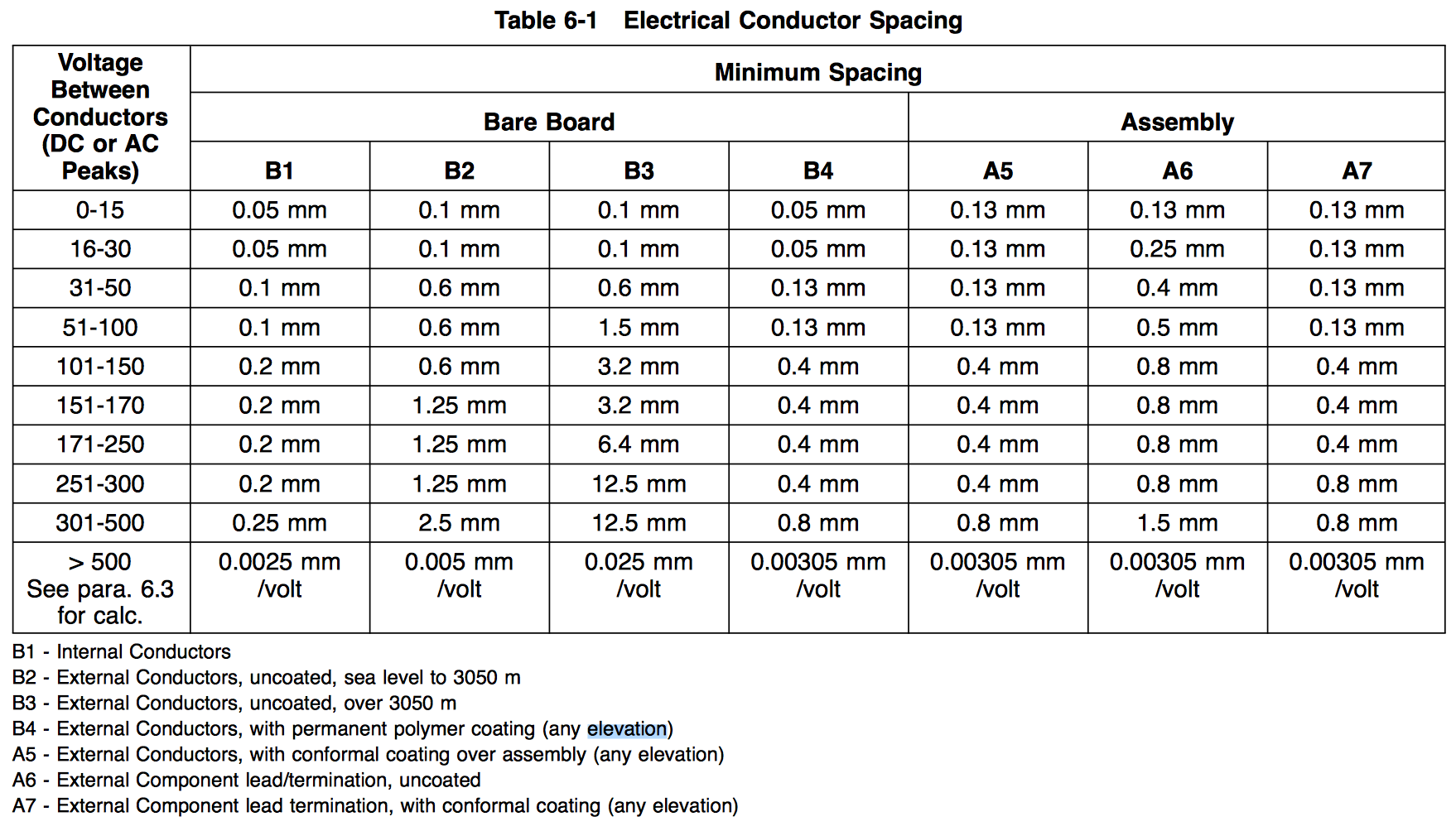
Since my boards have external conductors with permanent polymer coating (solder mask) and no conformal coating over leads/terminations, B4 and A6 best describe my design. 120VAC has peaks around 170v. This seems to imply that I would need 0.4mm or 15.7mil gaps between traces.
That’s more or less what I already have, but there’s also this note:
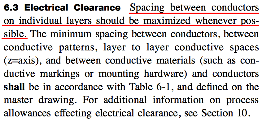
I certainly did not do that. While it’s still unclear to me if another 2-3mil of spacing around the traces would make my device certifiable, there’s no point in splitting hairs when I can completely remove the ground plane from that half of the circuit.

I’ve also added labels to the 120V connections so I don’t accidentally plug the neutral line in series with the fuse as I did the first time I assembled this box to give to my dad.
I’ve ordered new PCBs and instructed my dad to not install the charger cable until I ship him the new boards (the first ch00ftech RMA service). I’ve already updated the project files at the end of the post.
Anyway, if you haven’t read it already, enjoy the post!
Background and Motivation
So yeah, I’m obsessed with Tesla. Honest to god, this was my dating profile picture for a while:

(The caption at the bottom pointed out that it wasn’t actually my car)
If I had  600 which is a little out of my budget, so I had to make a device that would sit around my father’s existing charge cable and not require any modification in case he wants to remove it later.
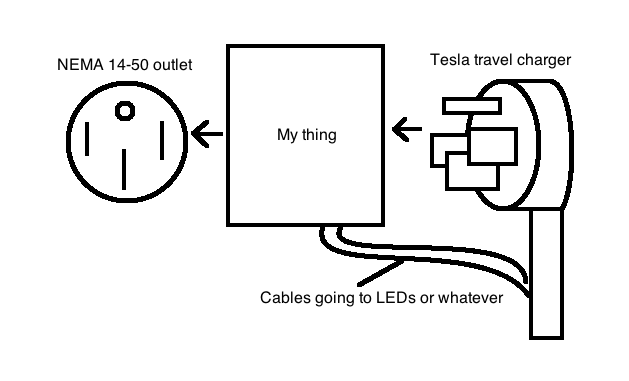
Based on these criteria, I needed something that would sit between the charger and the outlet (in order to measure current) and then have something that would wrap around the charger cable to illuminate it.
Something like this doodle (you’ll have to excuse the quality of the drawings. I’ll be stuck on an airplane for the remainder of this post):
NOTE
I am not an electrician and what I’m showing in this blog post is not a UL listed product. It has not gone through the important testing phases that any similar electronic/electrical device has. That being said, it was designed and built to be safe based on my personal interpretation of safe product design. The schematics and design of this device are presented with no warranty as to their safety. It is up to the reader to assess the safety of any device they build based on this design.
I don’t usually put a disclaimer like this on my projects, but I also don’t usually make things that deliver 9600 Watts!
Form Factor Design
Ideally, the form factor of my device device would look something like this:
A box with a plug on one side and an outlet on the other.
If I felt comfortable fabricating something and shoving it into a 240V socket, I may have gone with something like this, but safety concerns limited me to more or less off-the-shelf hardware. There aren’t too many consumer needs for an off-the-shelf enclosure shaped like this, so I was going to have to try something a little different.
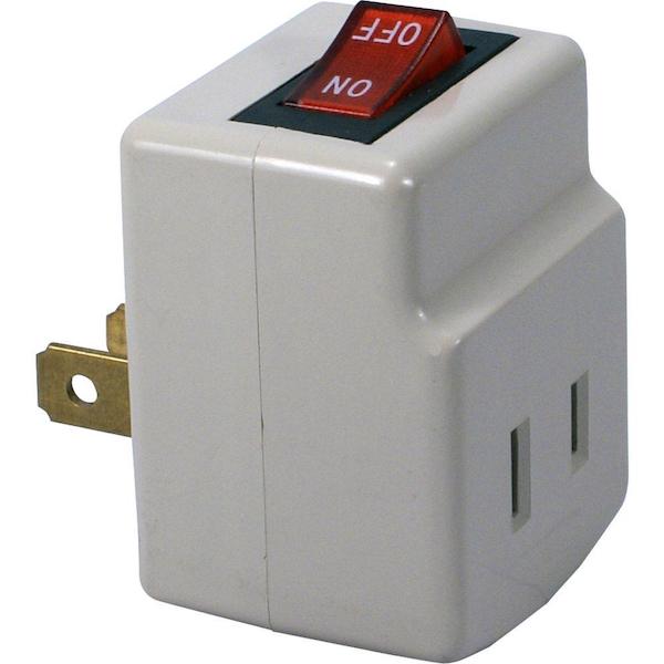
Thinking “outside the box” a bit, I realized that what I’m doing is essentially making an extremely small extension cord with some room for some circuitry somewhere in the middle. Googling around a bit late at night, I found this design:
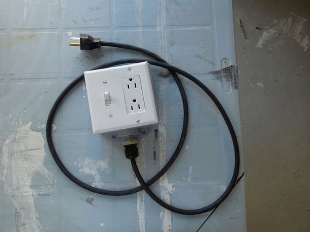 This is more or less exactly what I needed! This design uses all off-the-shelf components available at any major hardware store to essentially create a portable junction box with a power cord and plug.
Setting out to Home Depot, I looked for junction boxes that would give me enough space for my circuitry and a NEMA 14-50 outlet as well as some way to connect the cable and plug.
NEMA 14-50 provides a 240V service at up to 50A. There are three current carrying lines (two live wires out of phase and a neutral) as well as an earth ground The outlets are much larger than a typical power plug, so they require a “two-gang” junction box in order to have enough room.
240V is pretty easy to deal with (almost any insulated wire is rated for 600V), but the 50A was going to be a problem. A 50A service requires at least 6 AWG wire which is massive!
And also very inflexible.
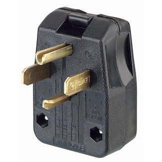
I picked up a Leviton NEMA 14-50 plug kit to go with it.
The 6 AWG cable is a little less than 3/4″ in diameter, so I made sure to pick up a two gang junction box with 3/4″ holes:
Strain relief on the cable entering the box was going to be important for safety, so I also picked up a 3/4″ clamp connector:

This connector has a nut that tightens it in a 3/4″ hole and then provides a clamp to hold the cable firmly and keep it from getting yanked out or otherwise damaged.
Issues
When I got home, I noticed a few immediate issues.
Firstly, even though the cable gauge was 6AWG and matched the specification for the Leviton plug kit, it still really didn’t look like it was the right fit:
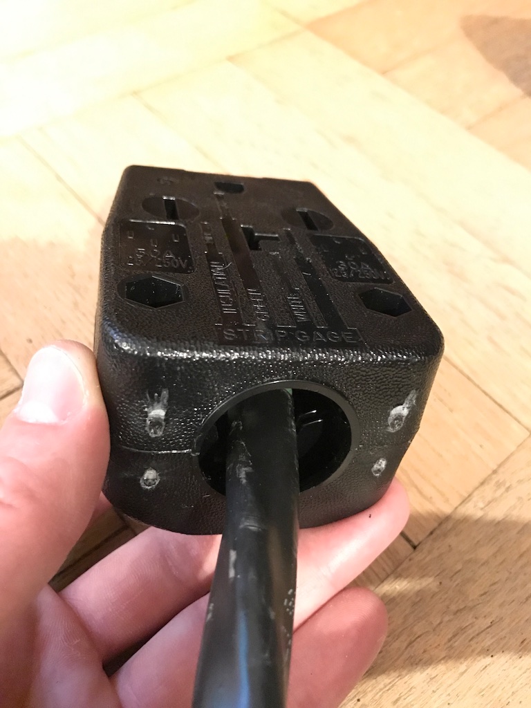
The inside of the box has some things you can toggle around to accommodate narrower cables, but even at its slimmest setting, clamping the plug shut provided barely any pressure on the black cable shielding. With such weak strain relief, any tugging on the cable would pull directly on the electrical connections which could cause a serious safety problem.
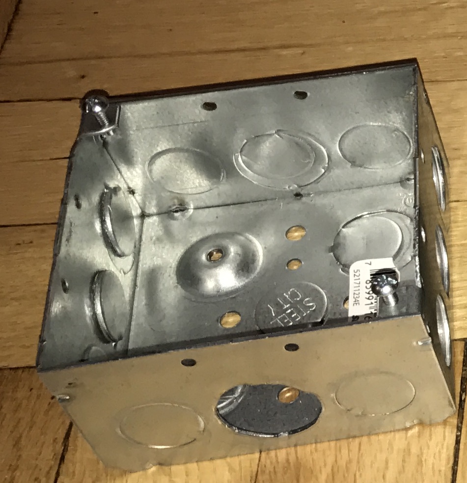
Secondly, I didn’t feel super comfortable with the electrical box. This box was clearly meant for indoor installations where people wouldn’t be touching it frequently. All over the box are “knock-outs” which are disks of metal that you can bend and break out to make more holes available for wiring. These knock-outs aren’t very securely fastened, and with a small amount of force, a user could push one into the box where it may interfere with the circuit, or at worst, short out the 240V supply.
Looking around some more, I found that waterproof junction boxes don’t use knock-outs and instead have threaded slugs that you can remove from the holes you need. Though these could still be affected by the end user, it was much less likely to happen by accident, and I could even lock the threads with some epoxy if I needed to.
I ordered an outdoor two gang junction box off Amazon, but then had to order a second one when I realized the first had 1/2″ holes:
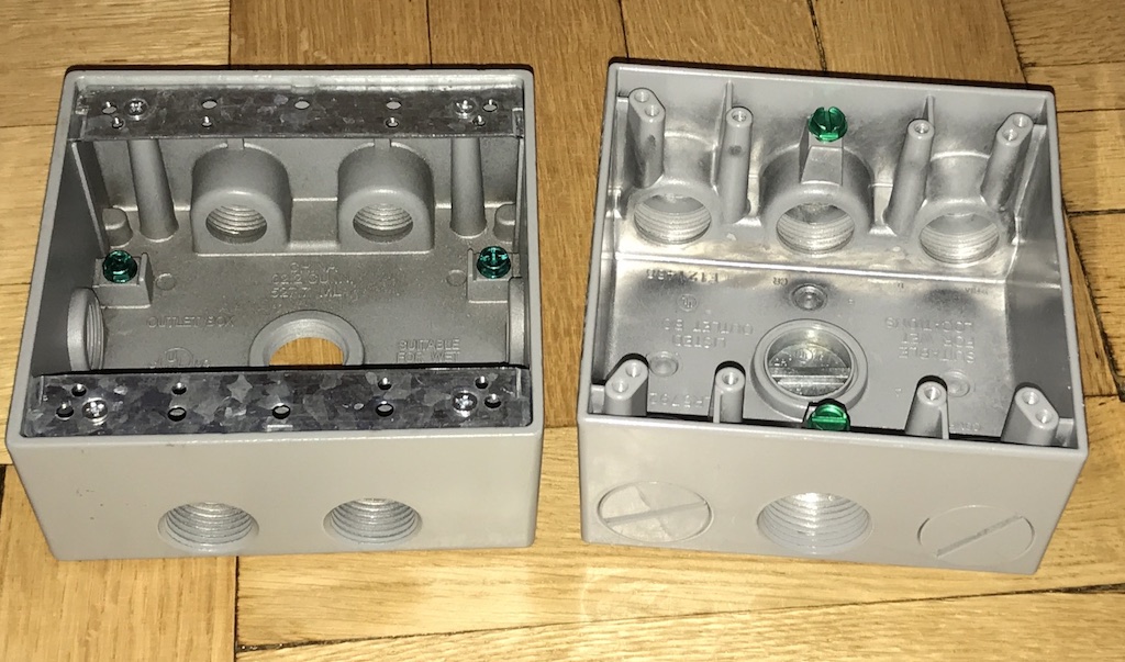
Oops.
Instead of connecting with a nut, the clamp connector would now simply screw into the threaded holes in the box.
I still didn’t have a great solution for the plug though. It just didn’t look right.
Through googling, I did eventually find an answer, but I’d like to point out that when it comes to home wiring, there are a ton of very helpful people online who are also entirely wrong. Dangerously wrong. Like I said in my disclaimer above, I’m no electrician, but even I know it’s a terrible idea to mount an outlet with no junction box directly to your drywall. And then cover it with a metal wall plate also screwed into drywall with no safety ground connection. If you search for tutorials on wiring your garage for an EV, one of the top results has someone doing exactly that. Be careful out there and don’t believe everything you read.
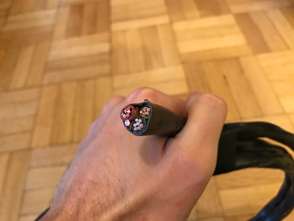
What I eventually learned is that the 6AWG cable I picked up is meant for permanent installs, not mobile applications. What I actually needed was “generator cord” or 6AWG SOOW portable cord.
Though the wire gauge is the same, this cord has a larger quantity of much smaller copper fibers surrounded by a very thick rubber coating. This makes the cord much more flexible while also providing ample protection for the conductors.
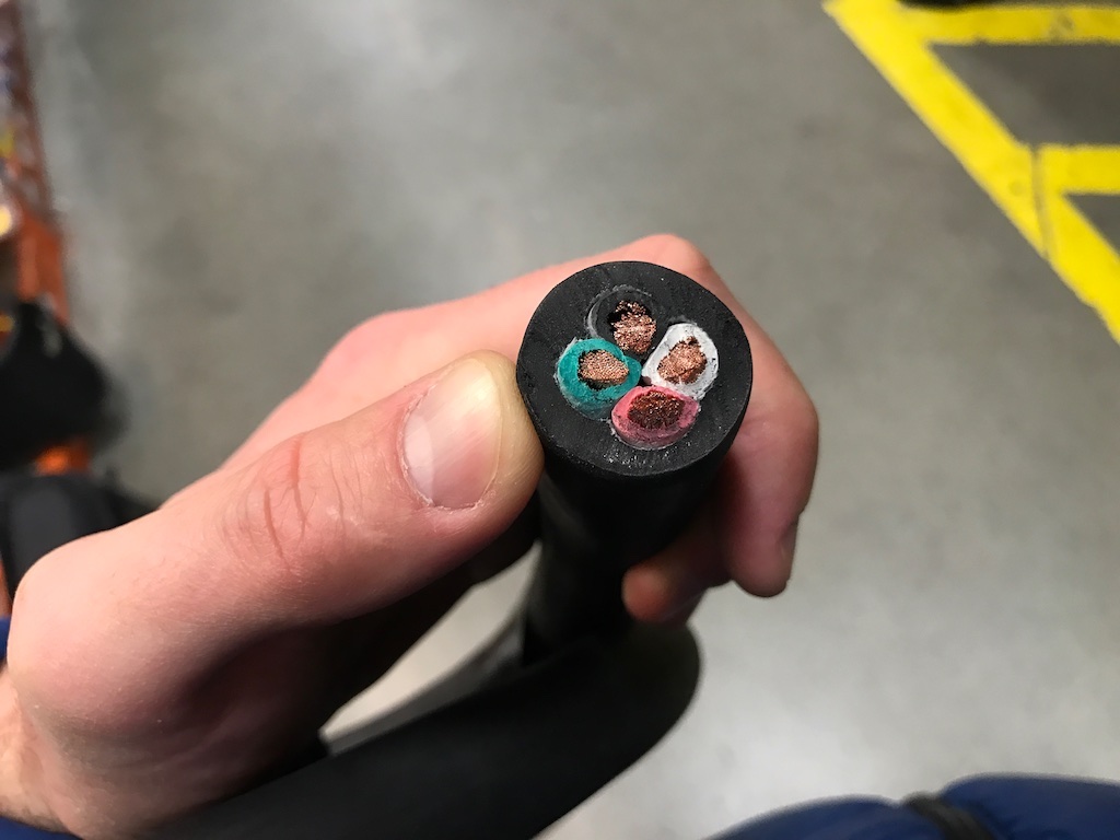
It also costs $5/foot and makes the cord 1″ in diameter which is too wide for my junction box.
So finally, thanks to the new generator cord, I needed to buy yet another junction box, this time with 1″ holes:
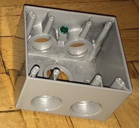
Sadly, due to their size, none of these holes are centered. Would have been a nice aesthetic.
Even with the new cord and junction box, I still didn’t love the idea of a clamp connector. The 1″ version kept the cord secured, but the metal squeezed down hard on the wire insulation and almost cut into it. I’m sure it would have been safe for stationary uses, but I wanted something a little better.
It also just didn’t look very good.
Taking some notes from that DIY extension cord instructable I looked for the same kind of dome-shaped connector but one that would fit a 1″ cord into a 1″ hole.
What I found was this:

This type of adapter is often called a “gland” (gross). In addition to evenly grasping the cable all over its circumference, it also provides a watertight seal. I wasn’t planning on using my device outside, but it was a nice plus.
The rest of this blog post will deal with the electronics and firmware design which is typical for me, but everything I’ve talked about so far was entirely new and was certainly the most challenging portion of the project. I was confident I could measure a current and light up some LEDs, but if I couldn’t make it safe, I wasn’t going to feel comfortable giving it to my father.
With that out of the way, let’s get into the electrical design!
Table of Contents
Background and Form Factor
Very cool, nice job!
Slick project! Don’t have a tesla myself but could use some of your ideas for my future projects.
Pingback: Animated EV Charge Cable Enlightens Us | Hackaday
Pingback: Lit Up & Animated Tesla Charging Cable Is Coolest Homemade EV Device We've Seen - Video
Have you ever thought of working with a firm like evannex.com to make this a product? Or of building these for other folks ()I’m about to get a model S and would love to have one). Even if you sold a kit of the parts, with instructions, that would be cool. Or (better yet) sold the assembled unit that plugs in, and let the purchaser assemble the cable, LED strip, and loom part.
We provides OEM production services, including PCB, PCBA, from design, procurement, proofing to mass production, etc. to provide a series of complete services to ensure the smooth progress of the project in the production stage!
w7j2vv
up6yfa
pnzscf
myynvg
o79l7j
wwgsml