
Designing the Car
In a typical pinewood derby race, it’s advantageous to get your car as close to the 5oz weight limit as possible in order to minimize the impact of resistance on your car’s speed. Unfortunately, I had a feeling getting that much weight to hover was going to be difficult, so I planned to make my car as light as possible.
I found a collection of random balsa wood scraps off Amazon:
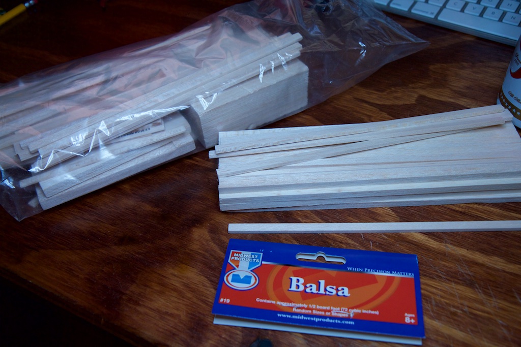
These turned out to be super conveniently sized. One of the scraps was just about the proper dimensions for a car (assuming the “wheels” are just electromagnet treads along either side).
And they were about as thick as one of the batteries I planned on using:

In the off chance that my car didn’t hover perfectly, I also ordered a roll of Teflon tape (no, not the plumbing kind). This tape has an adhesive on one side and is great for making surfaces slippery:

With some bits and pieces and a pretty fuzzy picture of the final product in my head, I set out to design the circuit.
The Circuit
To be perfectly frank, most of the EM theory I wrote above I learned well after I designed my car. I only had two weeks to design and build it, and I got the idea from a physics demonstration I saw back in college which looked something like this:
So it looks like we need a coil of wire with an AC current above a plate of aluminum. You’ve got two weeks GOGOGOGO!
While very busy at work, I carved out about 10 minutes to shop for parts. I knew I was going to need something that could drive an alternating current through a coil and operate off a few series lithium ion batteries like I did with my car last year. That means around 20V and maybe 3-4A. Twelve seconds of searching gave me the DRV8871.
It can run as high as 45V and can drive 3.6A. What’s cool is that it will automatically feather its output to limit at 3.6A. I figured this would be useful so I don’t blow it up immediately when I inevitably wire it up wrong. Y’know, because I planned this whole thing out so well.
The DRV8871 is controlled by two inputs. Having worked with motor drivers before, I knew that generally driving one high and the other low would pull current one way while doing the opposite would pull current the other way. Also, driving both low will ground both outputs and let you safely discharge the energy in the coil.
With this in mind, I grabbed and AND gate and an inverter. I figured I’d use the inverter on one of the inputs so I could drive both with a single square wave and have them always opposite each other. This would make it easier to drive them very quickly with a dedicated clock line on the MCU. The AND gate was so I could control one of them independently and force both of them low to shut down the system.
With that, I drew this:
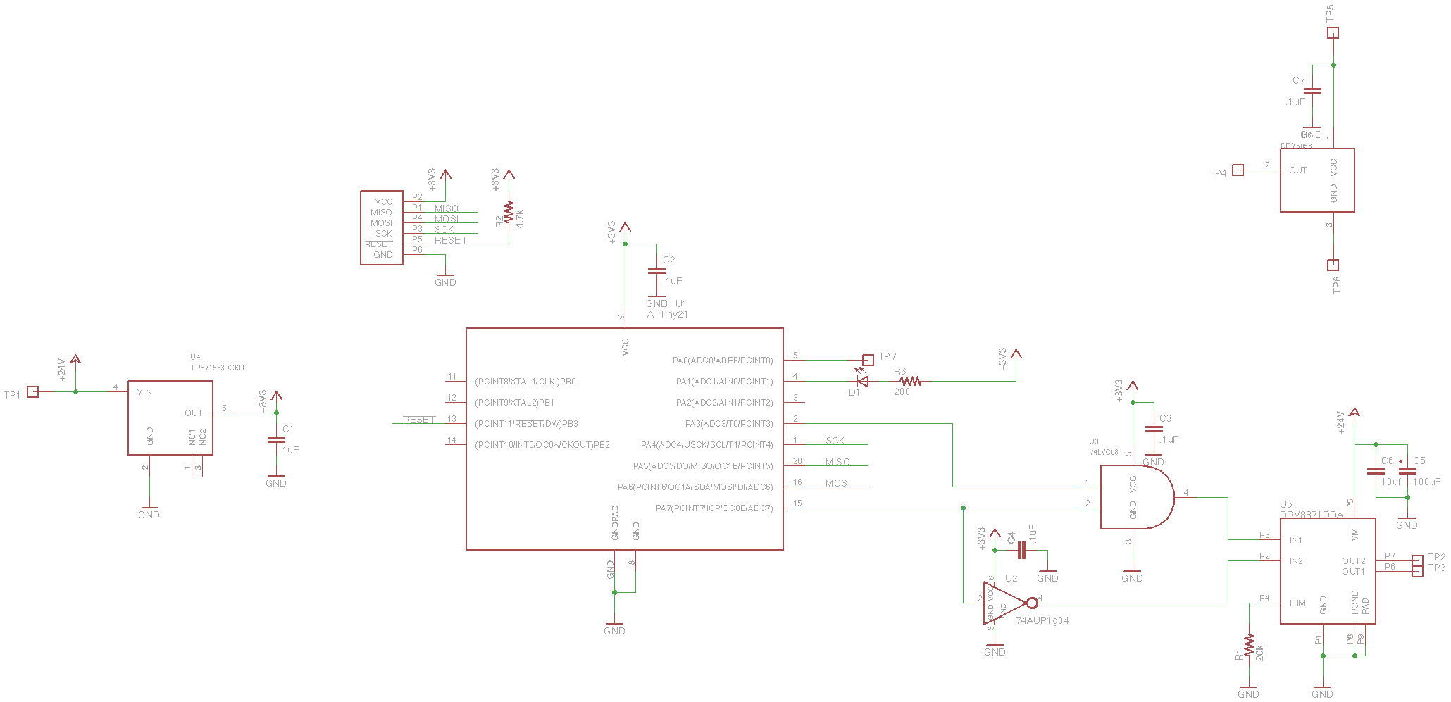
It wasn’t until I received the parts that I learned that the DRV8871 is actually shut down by driving both input pins high. Since I was using an AND gate, there was no way in this configuration that I could do this. If I wanted IN2 to be high, PA7 would have to be low which would consequently make the output of the AND and IN1 low.
Since I didn’t have enough time to order any more parts, I made do with what I had and mocked up this needlessly complicated logic:
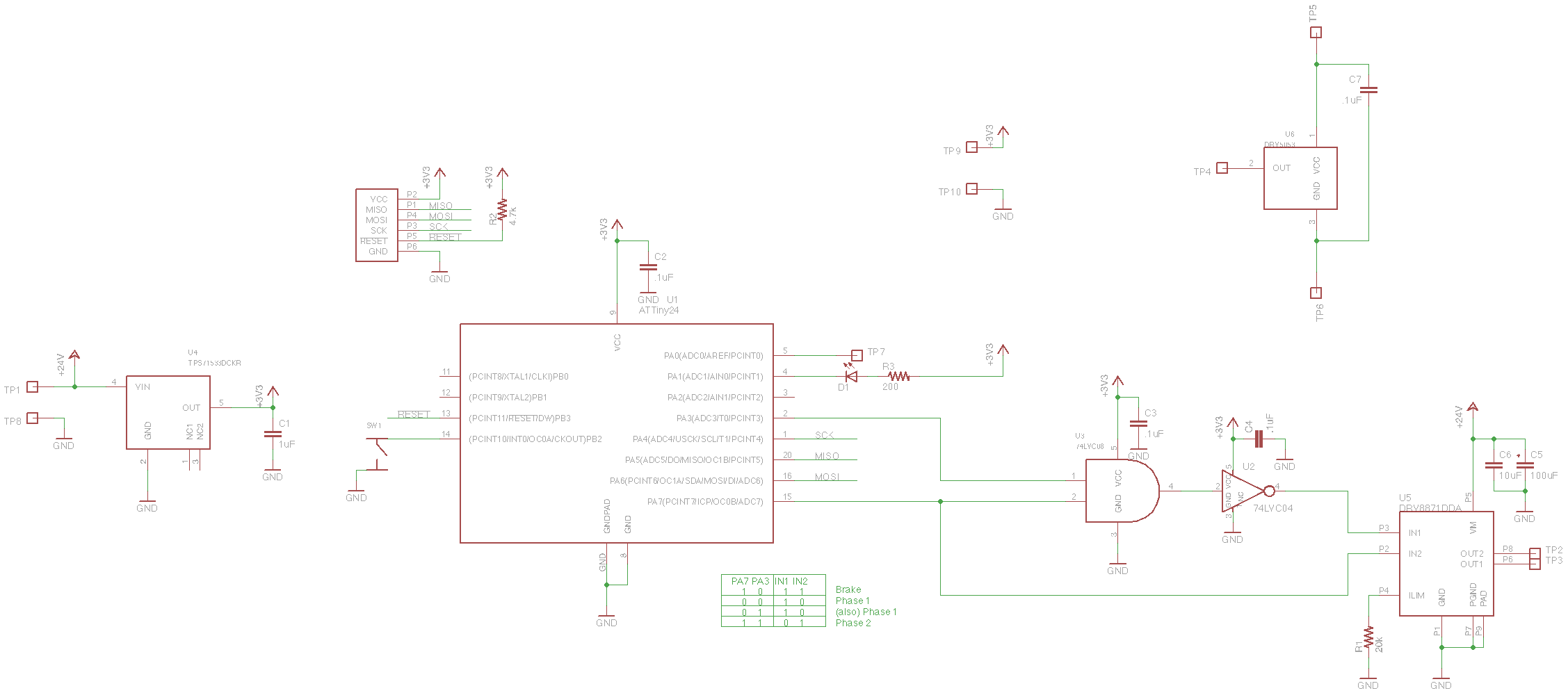
I even drew a little logic diagram to help me.
When driving an inductive load like a coil of wire, it’s important to find a way to discharge the energy in the coil. If you disconnect the coil immediately from the circuit, it will generate a very large EMF in an attempt to keep the magnetic field through it from dropping. This high voltage spike can often damage components. In a better designed circuit, I would be grounding both motor outputs briefly before reversing the flow of current. This was not a well designed circuit though, and you’ll see some voltage spikes on my oscilloscope plots later. I guess I was hoping the DRV88871 was smarter.
Off to the top right, you’ll see the DRV5053. This is a hall effect sensor (magnet detector) that I planned on using to detect when the race had started.
I knew this system was going to use a lot of power, so I was hoping to only enable it for the duration of the race: just a few seconds. Last year, I used an optical reflection sensor to detect when the starting gate was dropped, but I’m still not sure if it even worked. Knowing that the starting gate was a single steel bolt, I was planning on using this hall effect sensor and a magnet. As the magnet got near the ferrous steel bolt, the hall effect sensor was supposed to detect the bending of the magnetic field into the bolt and this signal could be interpreted by the MCU and trigger the hovering mechanism for a few seconds.
Unfortunately, I didn’t make it far enough to see if this would even work. Oh well.
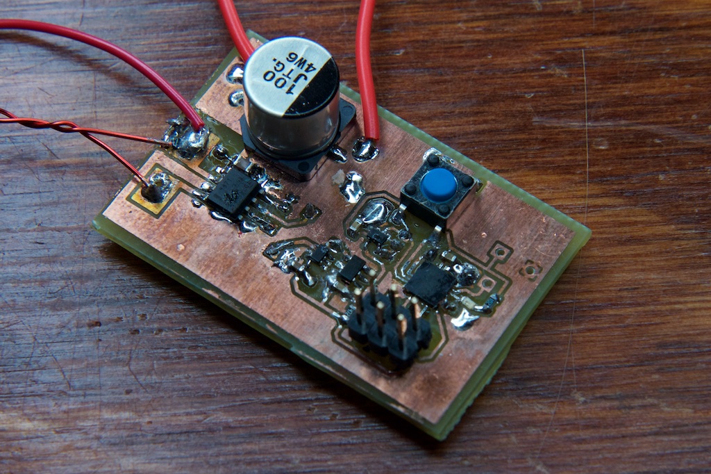
Using my usual method, I printed out a quick circuitboard of the design:
One thing I did slightly differently this time was add some large copper pours around where I planned to solder my coil wires. This would make the traces a little more robust when I started iterating on different coil designs.
Testing
After I printed my PCB, I soldered on the components, made a loop of about 50 turns of wire, and started playing around driving at different frequencies with some code on the MCU:
int main(void)
{
//set outputs/inputs
DDRA = 0X8A;
DDRB = 0x00;
PORTA = 0x82;
PORTB = 0x04;
    TCCR0A = 0X02;
    TIMSK0 = 0X04;
    TCCR0B = 0X01;
    OCR0A = 0X15;
    TCNT0 = 0;
    uint8_t freqCounter = 0;
    while(1) {
        while((PINB & 0x04)==0x04);
        TCCR0A = 0X12;
        PORTA = 0x88;
        _delay_ms(10);
        while((PINB & 0x04)==0x00) {
        }
        TCCR0A = 0X02;
        PORTA = 0x82;<
    }
}
I used the clock generator on timer/counter 0 to generate a high frequency signal when I held the debug button. The lower bits of TCCR0B determine the clock prescaler (here I’m just straight feeding the clock in) and OCR0A indicates the count that has to be reached in order to toggle the output. Once built, I started playing around with these two values to toggle the drive frequency and see what kind of performance I could get.
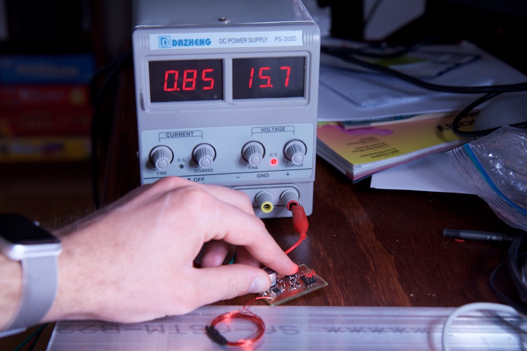
At around 15V and 600Hz, I got this:
Hey! Would you look at that! It floats!
And it only draws 2A!
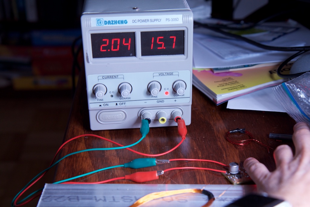
The coil heated up pretty quickly, but I had a feeling it would survive the seven seconds or so that I needed.
Issues
Feeling rather successful, I went to bed and spent the rest of the week gloating about my success to all of my coworkers showing many of them the above video.
Although I was floating a coil of wire, I knew it wasn’t perfect. Even a small amount of weight on the coil kept it grounded, but I figured that a little refinement to the design of the coil and the firmware and I’d have it working better in no time.
I knew that increasing frequency would increase the rate of change of the magnetic field which would probably increase my force as well. There was also this diagram on the Wikipedia page for electrodynamic suspension:
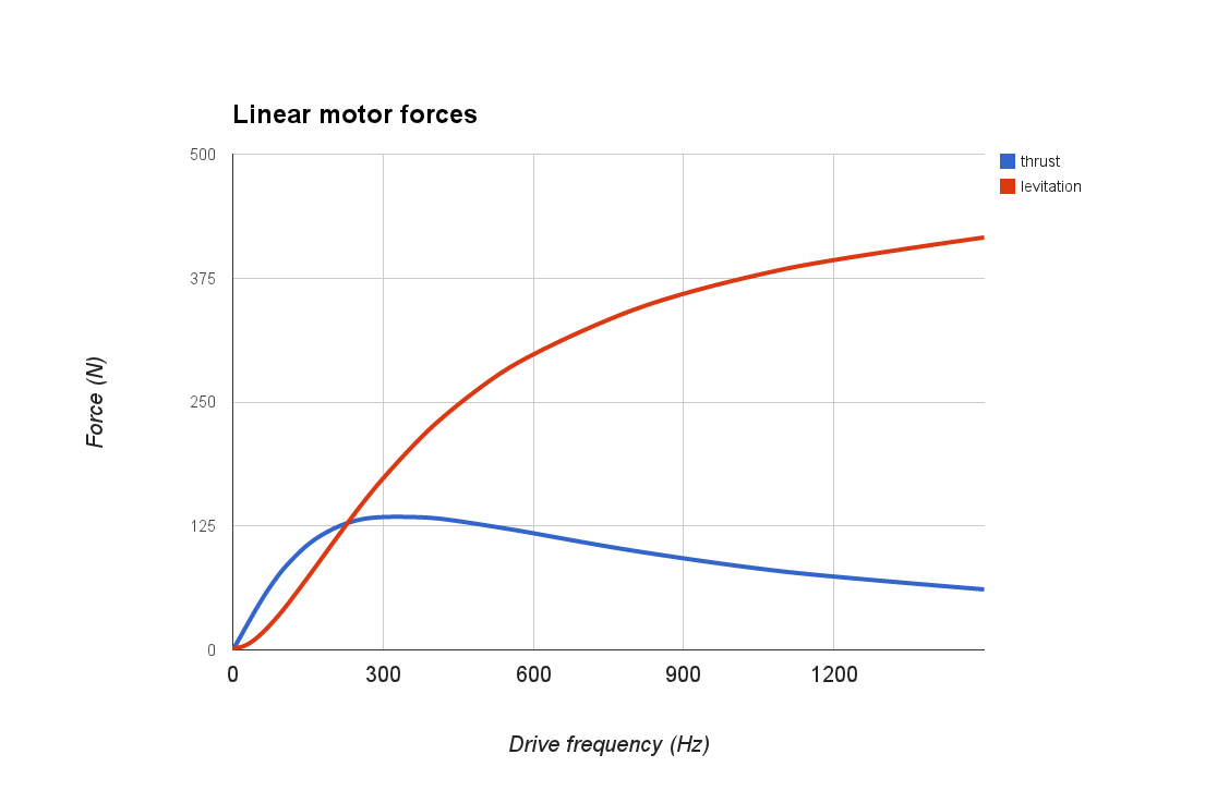
Which seems to indicate that a higher drive frequency delivers a higher force.
When I finally got back to testing, I increased the drive frequency all the way up to 170kHz which was nearing the 200kHz limit of the motor driver. Even increasing the frequency by a factor of 283, I still wasn’t able to float a single business card.
In fact, increasing the frequency far beyond a few kHz actually decreased the amount of force. Starting at around 100kHz, the coil stopped moving entirely and the system drew a very small amount of power:
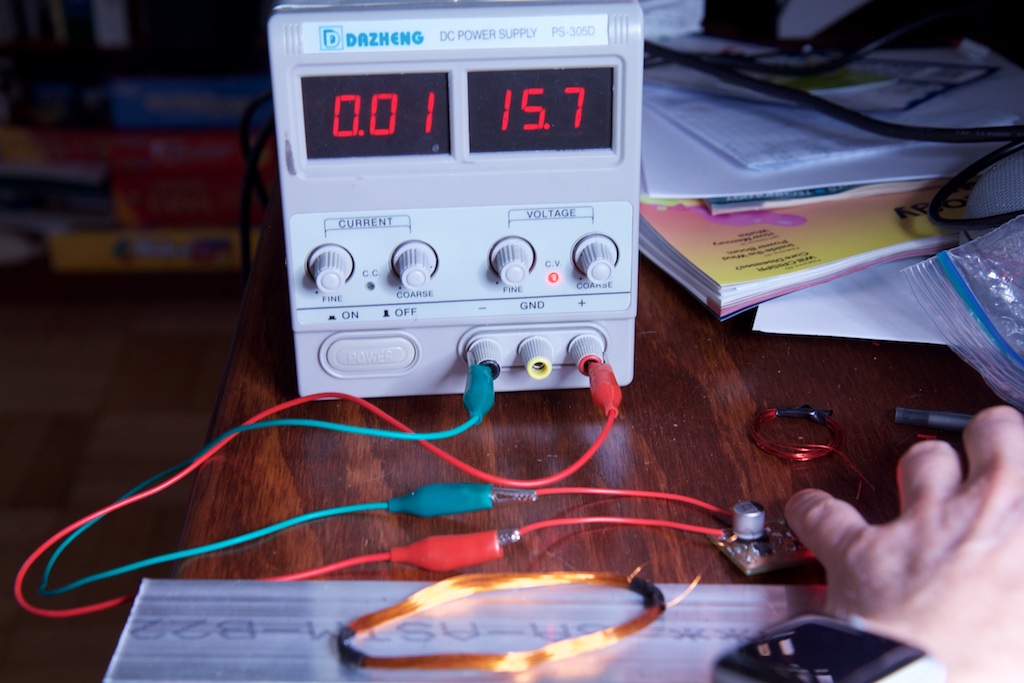
Of course, the inductance of the coil! The coil’s large inductance meant that the current would respond slowly to changes in voltage. With the voltage changing so rapidly, there just wasn’t enough time for the current to ramp up at all. That Wikipedia graph must be assuming current drive instead of voltage drive.
I later took some current measurements that demonstrated this fact (I’ll explain the details of the test setup later):
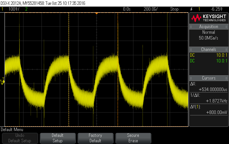
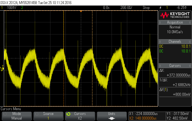
As the frequency goes up, the current can’t reach its maximum level before turning around. At very high frequencies, the coil drew very little current and generated very little magnetic field.
Ok, so how about a coil with fewer turns?
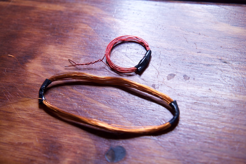
Well it drew more current, but it still wouldn’t float. In fact, it didn’t even produce enough force to wiggle. I wasn’t sure exactly what was happening here, but I figured it had something to do with fewer loops giving me less magnetic field.
I then realized that this was going to be a much tougher problem to optimize than I thought. Too many loops and I can’t drive it fast enough, but too few loops and I don’t get enough magnetic field.
I spent a solid two nights on this problem. I tried more coils of wire, fewer coils, different frequencies and voltages. I even tried different coil shapes. No matter what I did, I couldn’t seem to improve performance. I made a quick attempt to consult some old physics textbooks to take a more measured approach, but didn’t get very far, and with the race quickly approaching, I ultimately had to just give up.
Table of Contents
Designing and Testing the Car
Pingback: Fail of the Week: Pinewood Derby Cheat Fails Two Ways | Hackaday
Pingback: Fail of the Week: Pinewood Derby Cheat Fails Two Ways
Pingback: Fail of the Week: Pinewood Derby Cheat Fails Two Ways – Vloda.com
Pingback: Fail of the Week: Pinewood Derby Cheat Fails Two Ways – Celeb Like
Pingback: Fail Of The Week: Pinewood Derby Cheat Fails Two Ways - SLG 2020
drv3h1
t1ieiz
tbecyi
opddag
ed1673
jylhtp
paqc2q
ato3c5
xtj4kv
xz2lxa
83kcqw