
Optimization
Now that we’ve got a good model for our system, we’re back to the problem of optimizing it. The advantage now is that iterating and measuring accurately can be done much more quickly in simulation than in the real world.
The way I saw it, the maximum drive voltage was locked at 15V (what I can make with the batteries) and the maximum drive current was locked at around 3A (3.6A maximum drive on the motor driver). While I could tweak the geometry of the problem slightly by changing the shape of the coil, I figured that whatever was good for a circular coil would probably mostly work for oval shaped coils as well.
That leaves my two variables: drive frequency and the number of turns in my wire loop.
These aren’t independent variables though either. If I wanted to reach 3A peak current when driving my inductor with 15V, there was a maximum number of turns I could have for a given frequency. More turns would reduce the frequency, so I wanted to have just enough to lock me at 3A.
Relating number of turns to drive frequency requires calculating the complex impedance of my circuit.
Ideally, my circuit is just an inductor, but in real life, I have an inductor in series with a resistor. This isn’t the current-sense resistor, but rather something to represent the resistance of the wire itself.
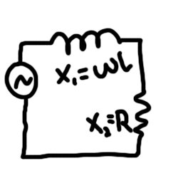
Calculating the current can be done by dividing the driving voltage by the impedance of both elements. Impedance is like resistance but for AC signals. For the resistor, the impedance is just the resistance, but for the inductor, it’s calculated by multiplying the inductance by the drive frequency measured in radians per second.
![\[\Large I = \frac{V}{R+\omega\times L}\]](https://ch00ftech.com/wp-content/ql-cache/quicklatex.com-932898f560a182cb9188331e25e01267_l3.png "Rendered by QuickLaTeX.com")
![\[\Large I = \frac{V}{R+2\times\pi\times L}\]](https://ch00ftech.com/wp-content/ql-cache/quicklatex.com-2a991e6df9308a399cbd4bbfe40e6811_l3.png "Rendered by QuickLaTeX.com")
![\[\Large 3A=\frac{15V}{R+2\pi F\times L}\]](https://ch00ftech.com/wp-content/ql-cache/quicklatex.com-d007227319838db76f755f132ff4f0ef_l3.png "Rendered by QuickLaTeX.com")
Where F is in Hz.
Now we need to find R and L in terms of the number of turns in our coil. R is easy. I did some rough estimates and got 0.047
![\[\Omega\]](https://ch00ftech.com/wp-content/ql-cache/quicklatex.com-5060d7d946cd178c2e892e089190f3ff_l3.png "Rendered by QuickLaTeX.com")
per turn.
![\[\Large R=0.047\times n \Omega\]](https://ch00ftech.com/wp-content/ql-cache/quicklatex.com-0b0c704f9b1ab53d16dcaa4f8a2e466b_l3.png "Rendered by QuickLaTeX.com")
I knew that the inductance would probably go as the square of the number of turns, so I figured I could measure a few coils with different turn counts and fit the results to a exponential curve.
![\[\Large L = C\times n^2\]](https://ch00ftech.com/wp-content/ql-cache/quicklatex.com-470e8bd3b8ae1d527706b6aa00045d36_l3.png "Rendered by QuickLaTeX.com")
Where C is some constant.
I created a new FEMM file that removed the aluminum plate and ran this script which sets the frequency to 0Hz and measures the flux linkage with different numbers of turns.
open(mydir .. "pinewoodnoplate.FEM")
mi_saveas(mydir .. "temp.fem")

print("Turns", "Flux linkage (Webers)")
for n=1,100,5 do
    mi_deletecircuit("Coil")
    mi_addcircprop("Coil",3, 1)
    mi_selectgroup(1)
    mi_setblockprop("30 AWG", 1, 0, "Coil", 0, 1, n)
    mi_probdef(0,"millimeters","axi",1E-8)
    mi_analyze()
    mi_loadsolution()
    x, x, flux_re = mo_getcircuitproperties("Coil")
    print(n, flux_re)
end
The results were as follows:
--> Turns	Flux linkage (Webers)
--> 1	4.58679685255453e-007
--> 6	8.895384045982092e-006
--> 11	2.812405650058698e-005
--> 16	5.825146605148131e-005
--> 21	9.931023987847736e-005
--> 26	0.0001513167909321755
--> 31	0.0002142810618512337
--> 36	0.0002882097353929007
--> 41	0.0003731076163811198
--> 46	0.0004689783275194304
--> 51	0.0005758246986315159
--> 56	0.0006936490016652185
--> 61	0.0008224531010623734
--> 66	0.0009622385544869389
--> 71	0.001113006682853116
--> 76	0.001274758620530347
--> 81	0.001447495352280627
--> 86	0.001631217741041961
--> 91	0.00182592654922964
--> 96	0.002031622455342566
Taking one of these in my formula:
![\[\Large C = \frac{0.008224}{61^2}\]](https://ch00ftech.com/wp-content/ql-cache/quicklatex.com-ee40f79aa0329c654c9c682a9144e6f1_l3.png "Rendered by QuickLaTeX.com")
![\[\Large C = 2.21E-6\]](https://ch00ftech.com/wp-content/ql-cache/quicklatex.com-ae95c09c28750ec4054f6059fb250b94_l3.png "Rendered by QuickLaTeX.com")
The C was roughly the same for the other samples.
So now I have this:
![\[\Large 3A=\frac{15V}{(0.047\times n)\Omega+2\pi F\times 2.21E-6 \times n^2}\]](https://ch00ftech.com/wp-content/ql-cache/quicklatex.com-694e1d5516214338219afdadb15984d6_l3.png "Rendered by QuickLaTeX.com")
![\[\Large F=\frac{\frac{15V}{3A}-(0.047\times n)\Omega}{2\pi \times 2.21E-6n^2}\]](https://ch00ftech.com/wp-content/ql-cache/quicklatex.com-c35d084f926e712dd16ce8aa95c61109_l3.png "Rendered by QuickLaTeX.com")
Alright! So now all we have to do is write a script that varies the number of turns and picks the appropriate frequency using the formula so that the drive current is around 3A.
print("Turns", "Frequency (Hz)", "Vertical Force (N)")
for n=1,100,5 do
    mi_deletecircuit("Coil")
    mi_addcircprop("Coil",3, 1)
    mi_selectgroup(1)
    mi_setblockprop("30 AWG", 1, 0, "Coil", 0, 1, n)
    freq = ((15/3)-(0.047*n))/(2*3.14*0.00000221*n^2)
    mi_probdef(freq,"millimeters","axi",1E-8)
    mi_analyze()
    mi_loadsolution()
    mo_groupselectblock(1)
    fz=mo_blockintegral(12)
    print(n, freq, fz)
end
print("\n")
Results
--> Turns	Frequency (Hz)	Vertical Force (N)
--> 1	356875.2341701012	3.032920242455698e-005
--> 6	9442.85929299043	0.0008692223280760001
--> 11	2669.509379547187	0.002365091407911666
--> 16	1195.618497276422	0.00401456995558913
--> 21	655.6599448533292	0.00527401360891695
--> 26	402.6830415057284	0.005833300089283916
--> 31	265.6414531065834	0.005676795478527507
--> 36	183.9113709976705	0.004991921363593658
--> 41	131.717333248385	0.004052481581709609
--> 46	96.63730508888916	0.003111732953080059
--> 51	72.10774238586842	0.002310151461091151
--> 56	54.40686808775445	0.001684427198701054
--> 61	41.30277847373078	0.001218965249833751
--> 66	31.39470594084171	0.0008827367067708583
--> 71	23.76969638084918	0.0006454753151022183
--> 76	17.81349373847213	0.000482481104123163
--> 81	13.10142359563622	0.0003749290603228611
--> 86	9.332901647988576	0.0003088571720289507
--> 91	6.290766932263948	0.0002739996981329578
--> 96	3.815271413154512	0.0002628064612071788
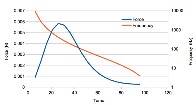
These results suggest that I would get the most lift at around 25 turns with a driving frequency of 400Hz.
Hey, I wasn’t too far off! It looks like the physics reward you for having a small number of loops at a low frequency. The 50 turns and 600Hz of my prototype is along the same scale, and when the differences in geometry and measured vs. simulated inductance are taken into account, I wasn’t too far off the mark.
Now the really important take home here is that even with the most optimal setup, at 15V and 3A, I only get around 0.0056N of lifting force.
How much power would I need in order to lift a 5oz (1.39N) car? Ideally, we’d like to keep the current down as much as possible to reduce the amount of power lost due to resistance of the coil. I locked the output current to 3A and varied voltage and turns/frequency. Rather than write another script that produces a 3D graph to handle the two independent variables, I just iterated a few times with the previous script while varying the 15V number until I got this plot:
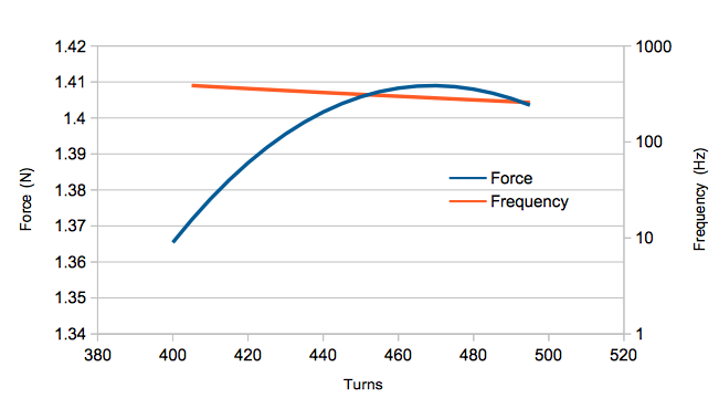
Alright, kissing the 1.4N rail at 470 turns! What this doesn’t show you is the input voltage used which worked out to:
2700V

Conclusion
As this blog post about a nonexistent hovering pinewood derby car nears 8000 words, I’m starting to wonder what I’m doing with my life…
Seriously though, it was a lot of fun digging into the physics behind how the car was supposed to work. My understanding of the mechanism was fuzzy at best going in; I didn’t even know about the inductive lag in the metal plate which is the whole reason why it works.
I also realized that a little simulation up front can go a long way. There is no way in hell my car would ever work. Even if I were to somehow get the weight of the frame well below 5oz, I’d still need to stack up roughly 730 of my Li-po batteries.
Not gonna happen.
Moving on, I might like to try experimenting with the Hendo Hoverboard design. Rather than using all electromagnets, it takes advantage of high strength permanent magnets and physically moves them in a manner that generates lift. It’s much more efficient than what I was doing if a little more difficult to construct.
Anyway, I hope this was informative! And I’m open to suggestions for next year’s race!
Relevant project files can be downloaded here.
Table of Contents
Optimization and Conclusion
Pingback: Fail of the Week: Pinewood Derby Cheat Fails Two Ways | Hackaday
Pingback: Fail of the Week: Pinewood Derby Cheat Fails Two Ways
Pingback: Fail of the Week: Pinewood Derby Cheat Fails Two Ways – Vloda.com
Pingback: Fail of the Week: Pinewood Derby Cheat Fails Two Ways – Celeb Like
Pingback: Fail Of The Week: Pinewood Derby Cheat Fails Two Ways - SLG 2020
drv3h1
t1ieiz
tbecyi
opddag
ed1673
jylhtp
paqc2q
ato3c5
xtj4kv
xz2lxa
83kcqw
6d4rgf
27fqp9
4tzbo7