I was recently asked to create something for a charity auction in my home town, and I took it as a good opportunity to re-make my famous shutter shades.
Motivation
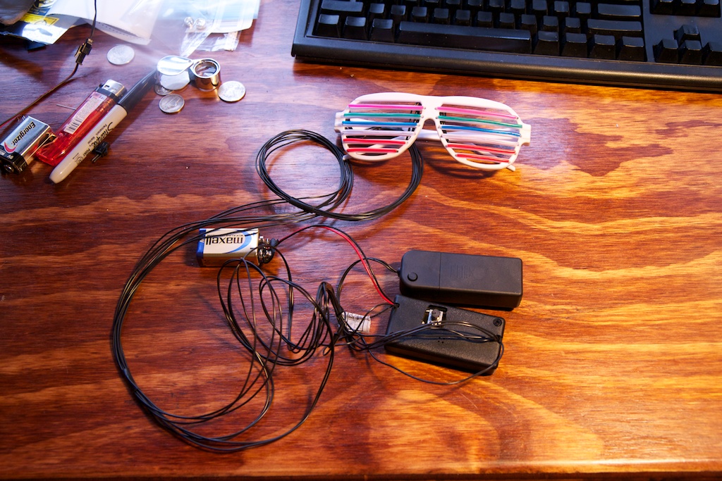
So it’s been almost a year since I made my last pair of shutter shades, and there are a few things I was hoping to improve on this time around. First and foremost was the form factor. The last pair of shades were made in basically 12 hours, and I wasn’t too concerned about aesthetics:
Seriously, I’m surprised I didn’t strangle much less electrocute myself.
In addition to an improved wiring job, I wanted to incorporate the power supply box into the controller box and make the whole thing more compact. On top of that, I figured I’d stick to a single color instead of having the gaudy rainbow effect (as if they aren’t gaudy enough already…).
The main difference with my new design is how the EL wire is controlled. Before, I had the entire box controlled with an analog circuit. I like to make things analog whenever possible, and given how simple a graphic equalizer is, it wasn’t much of a challenge. This presented a problem this time around though.
The new glasses will be set up on a display for a silent auction, and keeping in line with the “silent” aspect, there won’t be any loud music to show them off. This makes them a lot less desirable as a simple description card really can’t convey how cool they are.
This meant that I had to incorporate some kind of “demo” mode which eventually turned into making a full-on digital sequencer that can either react to music or play back pre-recorded patterns.
Wiring
If you’re curious about the specifics of my wiring job, I recommend checking out the first version of these glasses in the link above.
One of the issues with the previous set of glasses was how stiff the wires were. I was using threaded wire, but at 24 gauge, I was having trouble closing the glasses without putting substantial strain on the solder joints. Electrically, the gauge of the wire isn’t very important as even a fairly large amount of series resistance will have a small effect on such a high-voltage low-current signal.
This time I purchased 30 gauge stranded (7/38) teflon-coated wire. If you ever have the chance to purchase teflon-coated wire, DO IT. The stuff RULES. Teflon is a very heat-resistant plastic so you don’t have to worry as much about it shriveling up when you solder near it.
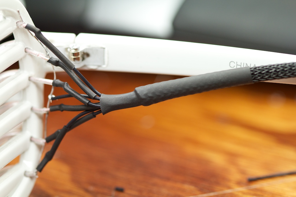
I also purchased some 1/8″ wire-sleeving to tie my conductors into one clean-looking cord and used some heat-shrink where I could:
I really surprised myself with how clean it all turned out.
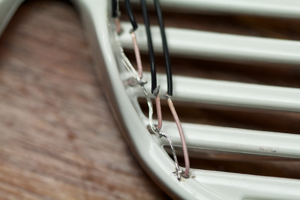
EL wire usually consists of an electroluminescent core wrapped in a phosphorescent colored coating. It’s this outer coating that gives the wire it the color you see because the chemical compositions of EL materials only allow for a small variety of core colors (namely blue, green, and white). For my first pair of glasses, I stripped this outer coating before bending the inner layers into the glasses to make their electrical connections. The result was a characteristic colored glow around the ends of each bar:
Although a white glow isn’t that big of a problem at the end of a white bar, I thought I would experiment with a new wiring technique that would prevent that from being a problem if I decided to make colored glasses in the future. It also improved the overall cleanness of the shades.
I drilled each hole twice: a smaller hole all the way through the glasses and then a larger hole about half way down. This way I could “counter sink” the EL wire and bury the core out of sight.
If I were to do it again, I would have just drilled the larger hole all the way through. The problem with using this technique is that it requires you to very carefully cut each length of EL wire because each end of the wire is up against a hard stop and you might end up with a noticeable amount of slack if you cut it too long.
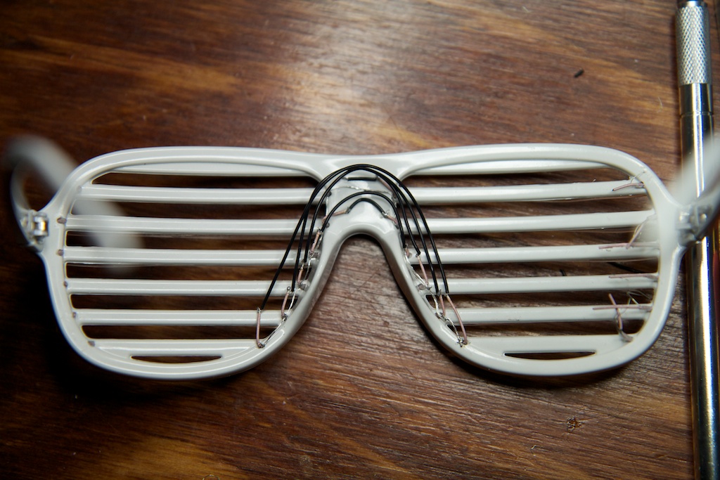
The inside nose-bridge actually turned out really neat thanks in part to my new thinner gauge wire:
Last time I did this, I wrapped all of my conductors in electrical tape. It ended up looking like garbage:
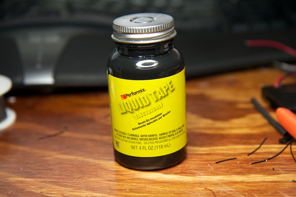
As well as not being a very durable long-term solution. This time around, I discovered another option. Usually when faced with insulating a bunch of exposed conductors, I reach for hot glue, but from now on, I’ll be using “Liquid Electrical Tape”:
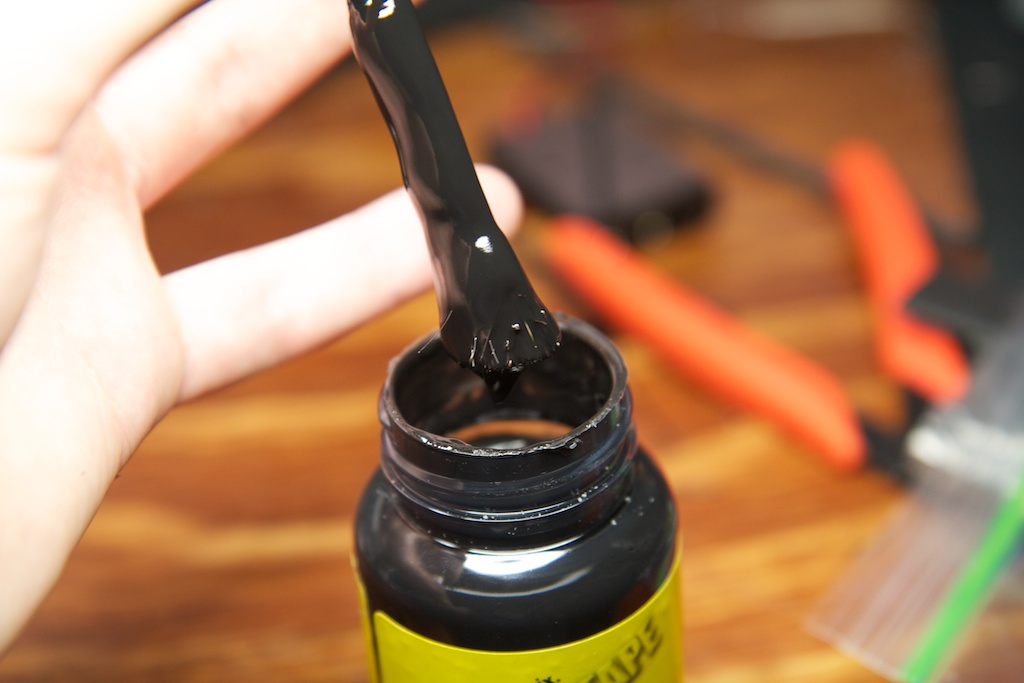
This stuff has the consistency of rubber cement, and although it comes with a built-in brush, it can easily applied using some cotton swabs:
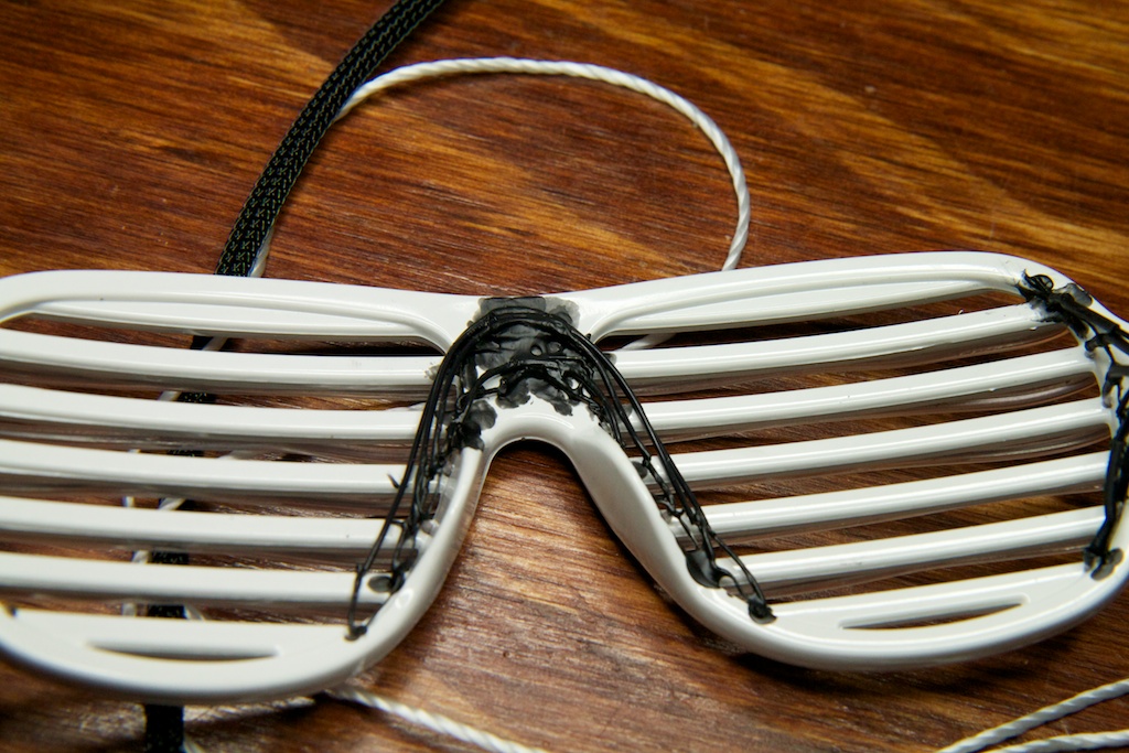
This let me easily paint on a very thin layer over not only the “live” contacts, but also the “neutral” wire. This offered better protection against shorts.
When dried it has the consistency of rubber, but can be peeled away if need be without too much fuss.
Different Types of Wire
What might not be clear by this point is that I actually made two pairs of glasses for this project. I thought it would be a good idea to purchase some high-quality wire from Ellumiglow and settled on this stuff. The wire was very sturdy and easy to work with. Unfortunately, I didn’t bother trying to light any up until I had finished the glasses.
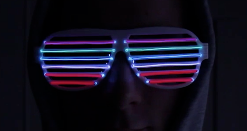
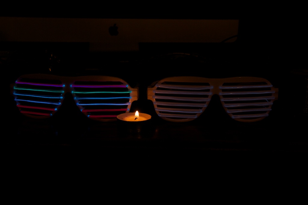
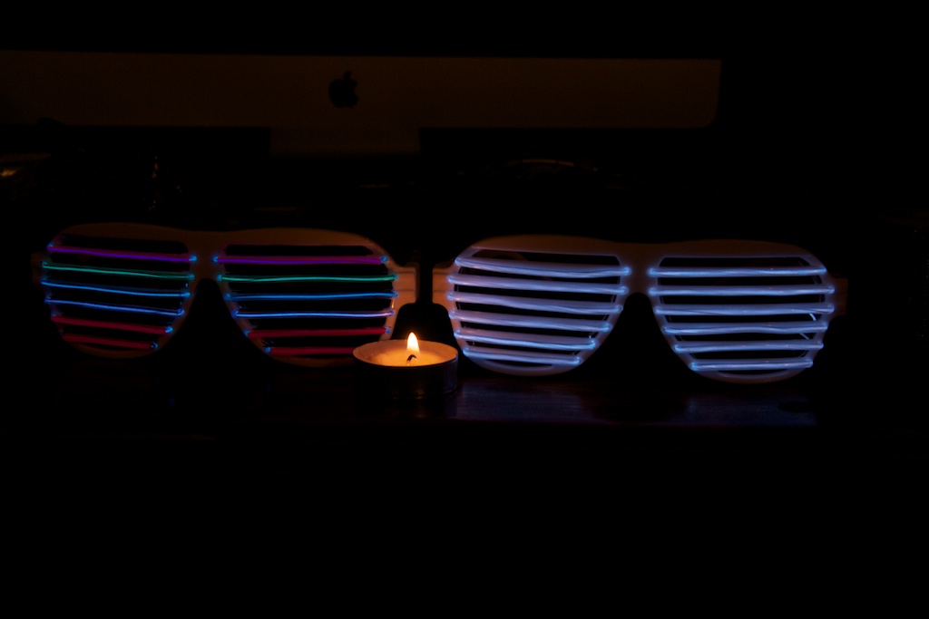
After going through all the effort of wiring up the new glasses, I connected my newly finished circuit and the result was less than amazing. The glasses were incredibly dim. What’s worse is that they got dimmer with every additional bar I tried to light up to the point where the illumination was hardly noticeable with all six bars turned on. Here’s the new glasses on the right with the old glasses on the left for comparison.
Interestingly, when I replaced my power supply with one of the high-power 9V supplies that I talked about here, the result was a lot better:
Although there was no indication of this on the order page or packaging, it appears that this new wire requires a lot more power to function. How much more? With the 9V supply, I measured 2.3x more current coming out of the 9V battery using the new wire than with the old stuff. It appears that the transformer I used in my supply wasn’t up to the task of powering this high power EL wire.
This isn’t too surprisingly considering how much brighter the glasses look when they’re powered up all the way.
This was great news but a little too late as I had already finished the power supply. Rather than attempt to build another power supply from scratch, I opted to recreate the shutter shades using some of the left over white wire that I had used on the first set. I’ll be building a high-power sequencer supply at some point in the future for the brighter set.
Circuit
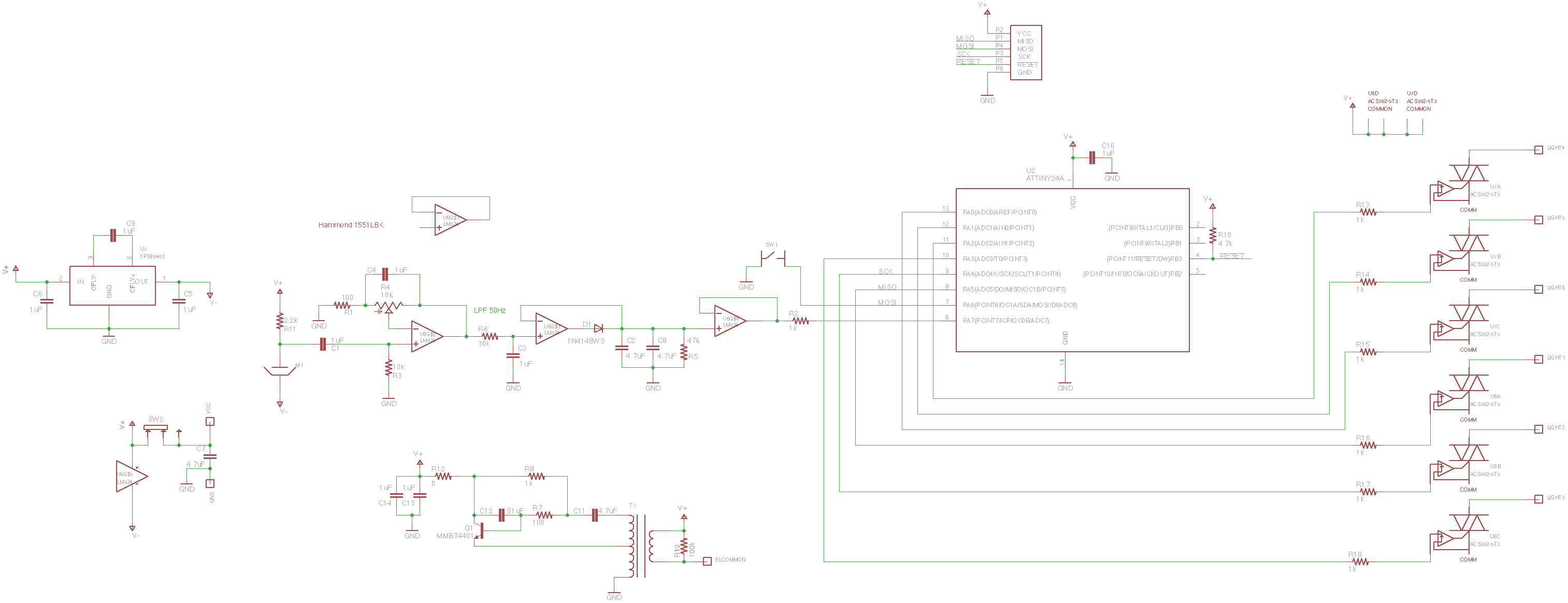
There isn’t much new with the circuit. Similar to my DJ Jacket, I opted for a dual-rail audio circuit using another charge-pump inverter. The audio stages are almost exactly the same. Honestly, if you want a play-by-play, just read my DJ Jacket post and the one for the original Shutter Shades.
The interesting and new part is the issues I had this time around.
Issues
I anticipated having some audio performance issues given that I’m powering both my audio circuit and the EL wire supply off the same battery. I figured any 2-3kHz noise coming out of the EL supply that got picked up by the audio stages would be eventually filtered out by the low-pass filter and wouldn’t cause too much trouble. I was wrong.
The big problem here is that even the tiniest little blip on the +V (and therefore -V) lines will get picked up by the microphone and gained up by a factor of two hundred or so. This means that even an imperceptible little wiggle can easily clip the gain stages. As an attempt to quell this, I added C4 to turn my gain stage into a low pass filter. This would help prevent the signal from hitting the rail and losing what useful information it had. I also added some bypass capacitance to the EL power supply, though C13 and C14 are only slightly representative of what I ended up adding:
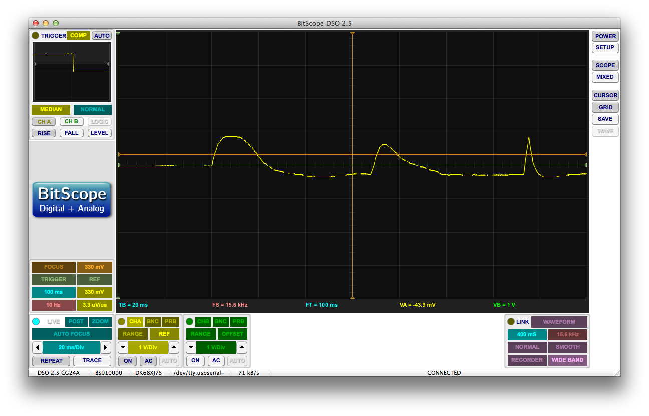
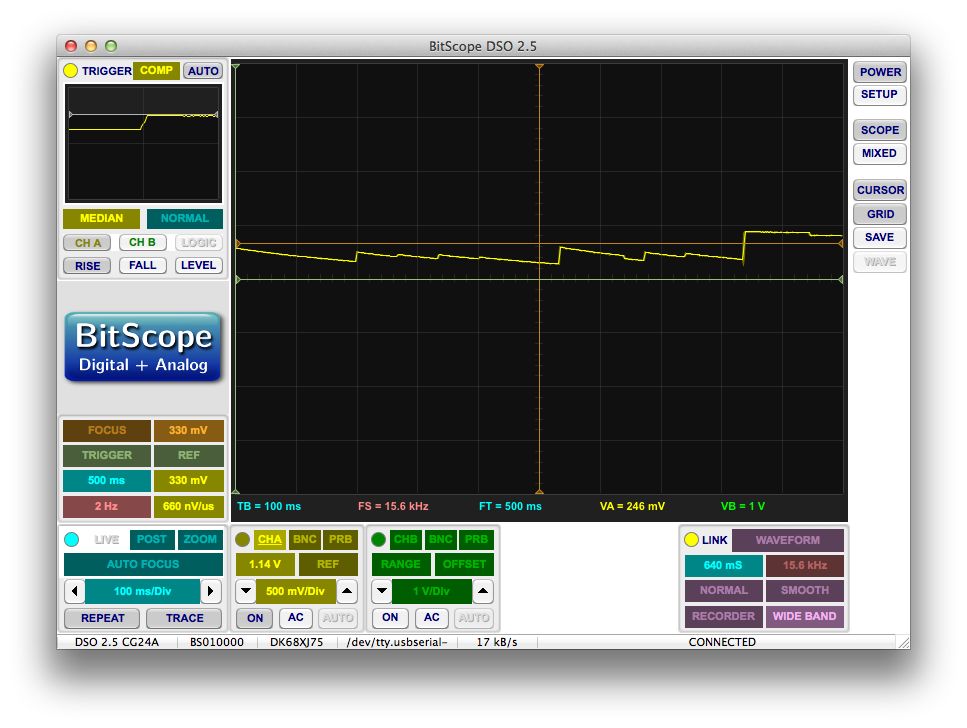
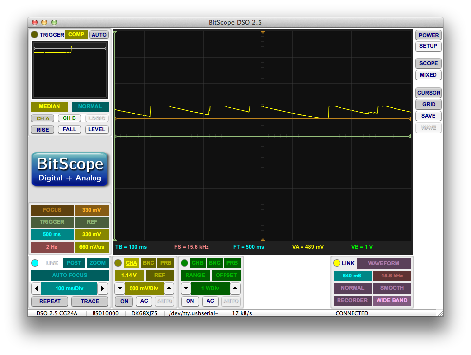
Even with all of these measures, I wasn’t able to get the noise down to a good level. The issue mostly arose during switching events with the TRIACs. As soon as I turned an EL segment on or off, the resulting current spike would cause a blip in my power rail and result in noise making it to the ADC of the micro controller. Here’s the noise going into the envelope follower:
And the resulting envelope:
Note that this is with a quiet input. This signal should be resting at zero, but instead, it’s flying up to as high as .3 or .4V causing my glasses to dance even with no music playing. This is especially bad considering that my audio stages clipped at around 1.5V:
I confirmed this issue by disconnecting my EL supply from the circuit and connecting an external supply to the appropriate rails. This completely solved the noise problem and silenced the signal. While this is not a practical solution, it did help narrow down exactly what the problem was.
Fortunately, I had a digital stage between this input signal and my EL wire. In the firmware, I was able to partially remove the noise by setting a rather high noise threshold. This helped, but it still isn’t perfect and I’m not entirely pleased with the result. With that kind of threshold, the range of the glasses is severely limited and as a result, it’s hard to tell if they’re really reacting to the music being played.
It’s even more upsetting because part of the advantage of having a digital stage was the ability to program in different reactive patterns. Rather than just have the glasses light up like the original pair, I could have had them light up from the top down, or even blink like eyes. Unfortunately, when I tried more sophisticated patterns like that, the current spike resulting from lighting up numerous bars simultaneously was large enough to put the glasses into a sort of feedback loop. A current spike would cause a dramatic change in the EL bars which would cause another current spike and so on. Once you got it started, it would continue to bounce around even with no music. I ended up having to limit myself to a single animation mode that used only a single bar of light at a time.
In the future, I’ll be sure to take more extensive measures to decouple my EL supply from the audio rails. If I make my next version using the 9V transformer, I’ll be able to use a linear regulator to drop that 9V down to 5V for the audio stages and hopefully completely block the power line noise from entering them.
Circuit
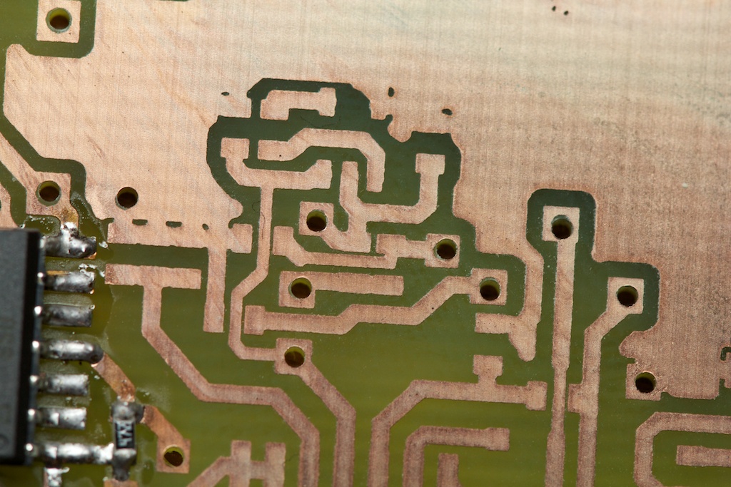
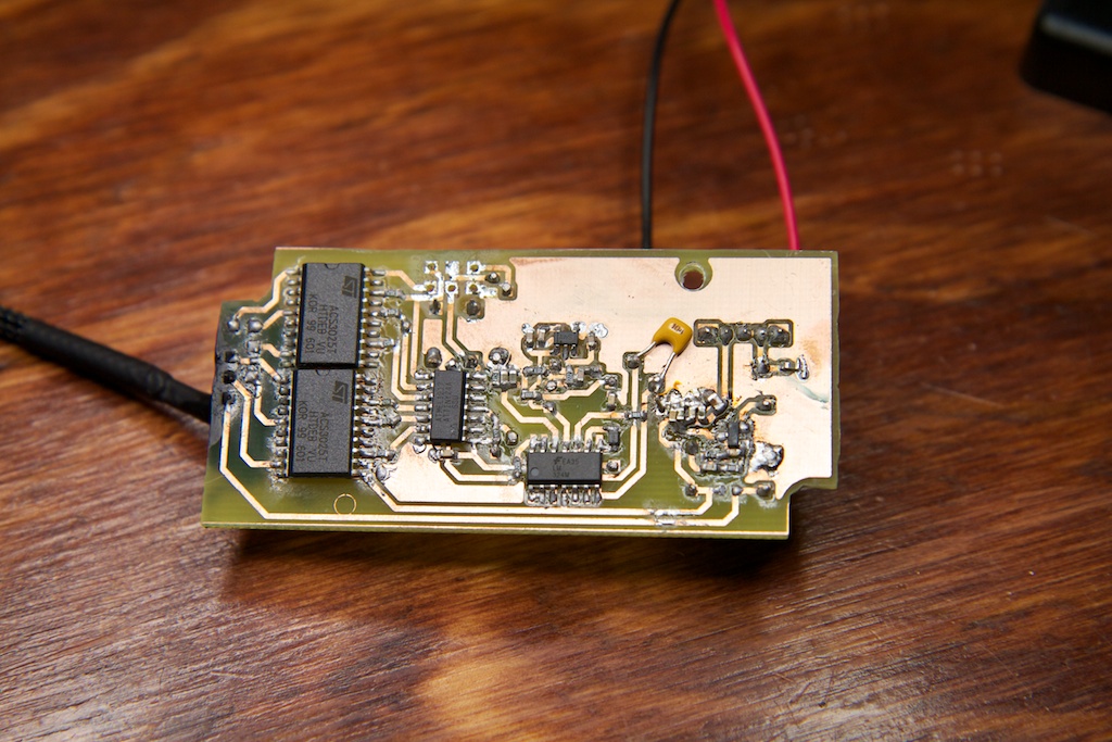
I’m really excited by how well my circuit board turned out. I had absolutely zero shorts this time despite some risky routing.
This is especially good considering how bad they’ve been in the past. Here’s the completed board.
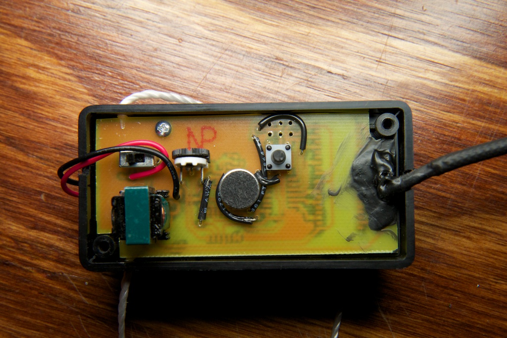
I was careful to choose parts this time that would fit nicely inside an enclosure. Given that this device was to be purchased by a complete stranger, I wanted it to look “near production quality”. I replaced my awkward potentiometer with a thumbwheel, and picked a switch that fit the enclosure well:
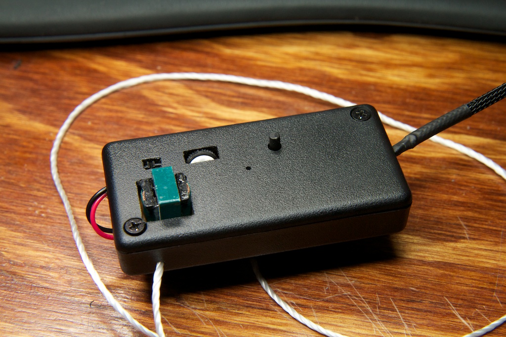
Unfortunately, I wasn’t able to fit the transformer entirely inside the supply, but in my defense, it’s a really big transformer:
One of the big complaints I got with the original pair that I wasn’t anticipating when I made them was that I couldn’t take the glasses off to let people try them on. This is because there was about 3 feet of wire running from the glasses down my shirt into a power supply in my pocket. This time I fixed that by adding a small bit of cord and turning the power supply box into a sort of necklace that can be easily slipped off.
A generous application of super glue attached the battery holder to the back:
Firmware
There really is nothing remarkable about this firmware. There’s a timer interrupt that causes the micro controller to either grab the next frame of the current animation from a lookup table or measure the incoming audio signal depending on which mode it’s in. You can change the mode by hitting the button.
Seriously, that’s it.
Demonstration
Here’s a video demonstrating some of the pre-programmed animations as well as the sound-reactive mode.
As you can see, the audio-reactive mode isn’t quite as good as the original. Also, they are a lot brighter in person, I didn’t have the settings for my camera set optimally.
Conclusion
While the glasses didn’t turn out as well as I would have liked, I think I still improved by leaps and bounds on the hardware and usability front. I’ll be sure to apply what I learned here on the electrical front in the next revision (which might be a Christmas present for a lucky sibling).
Regardless, I’m sure that the lucky winner of these glasses at the auction will love them as they are certainly the kind of eye-catching party-garb that you cannot buy in a store.






Awesome! I’m a beginner with electronics and your original glasses inspired me to try and make my own. I actually just (finally) finished building them on the weekend that uses a 9v inverter with a 5v regulator for the audio and I haven’t noticed any problems with it (so far). It was my first real project and I think it turned out alright. Here are some pictures and a video:
http://imgur.com/a/AITHg
http://www.youtube.com/watch?v=McQ_8yofNXU
Definitely didn’t turn out as good as your new ones but I’m just happy they work 🙂
Also I have been looking to get some thin hook up wire and was wondering where you got yours.
Thanks!
Holy crap dude, those are amazing! Really excellent job. I seriously laughed out loud in excitement watching the video. You should be proud.
I’m also glad to hear that the 5V regulator trick works. I’ll definitely be using that in my next attempt.
I got the wire off digikey. Part number A5851B-100-ND.
Pingback: Stronger-er Glasses (with digital EL sequencer) « adafruit industries blog
damn, I was working on a digital version of these, you beat me to it.
Pingback: Sound Reactive EL Panel Dimmer (for real this time) | ch00ftech Industries
Hi, if your el wire is very dimm is very likely you have a short between the el wires. Sometimes i suffer the same.
Good suggestion, but I think it’s just a different type of wire. It required a beefier power supply to operate, but it also got a lot brighter than my normal wire when powered properly.
Try short the el wires when power up. When i do that, the wire is very dimm, but not totally off.
In other way that problem can be the frequency needed to operate the wire. Diferents type of wire need diferentes frequencies..
http://www.kickstarter.com/projects/dropshades/dropshades-sound-reactive-technology?ref=category
Pingback: Soil Moisture Sensor | ch00ftech Industries
Pingback: Stronger-er Glasses (with digital EL sequencer) #ElectronicHalloween « adafruit industries blog
Pingback: Stronger-er Glasses (with digital EL sequencer) #ElectronicHalloween | electronics-trade blog