For the past few weeks, I’ve been blogging my assembly of the transistor clock which is now hanging on the wall of my new apartment. One of the most interesting aspects of that clock is how it keeps time.
Most clocks today use high precision crystal oscillators or dial out to some atomic clock somewhere (like your cellphone), but the transistor clock actually uses the 60Hz AC coming out of your wall socket to keep time. While this method was once common use, it’s certainly unconventional by today’s standards. I decided it would be fun to try to investigate exactly how accurate the 60Hz coming out of the wall is.
Goal
My goal with this experiment was to measure the accuracy of an AC clock source against a more predictable crystal-based time source.
Setup
To perform this experiment, I needed a micro controller that could take inputs from a crystal and an AC line, measure the difference between them, and send the output over RS-232 to my computer so it could keep a record of the measurements.
The idea is to produce a plot that shows how many seconds ahead or behind the AC clock is when compared to a “perfect” clock source at different points in a day. If the AC clock source was also a perfect time base, this plot would be a flat line.
AC input
Although my transistor clock looks lovely sitting on the wall, it doesn’t really have the right kind of input and output necessary to feed into a micro controller, so I basically rebuilt the clock’s time base going the easy route and using an LM-311 comparator. My schematic looked like this:
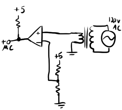
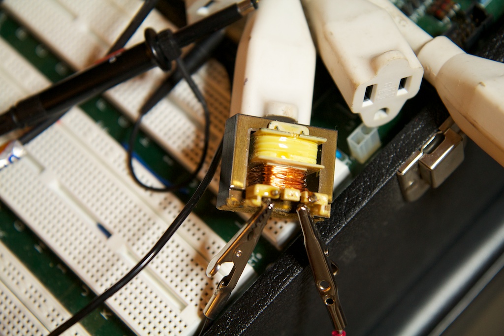
I found the transformer lying around in my parts bin, so I don’t know what its turn ratio is, but it gave me about a 3.5VRMS output. When compared against the 2.5V input supplied by the voltage divider, it produced a square wave on the output that matched the frequency of the AC input.
Oh yeah, that’s totally safe.
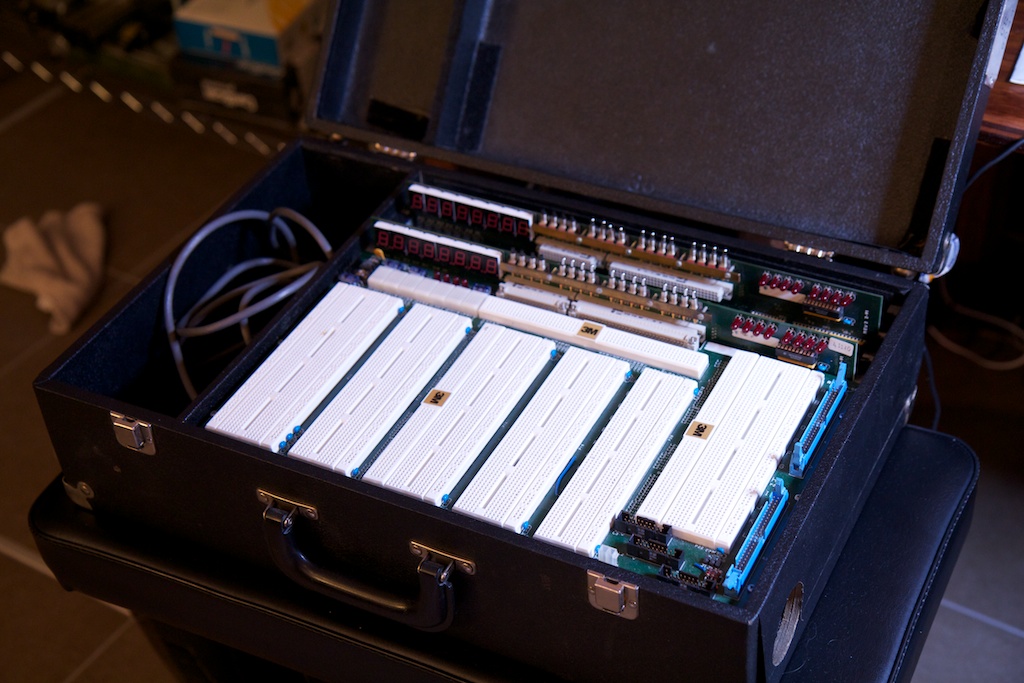
Oh by the way, I performed this whole experiment on an old MIT 6.111 lab kit that I acquired right before I graduated. They re-vamped the curriculum a few years ago, and were handing out the old kits that were just taking up room. I got one of the last good ones.
6.111 is an FPGA class, so the two boards in the back have very old onboard FPGAs that I don’t know how to program. Unfortunately, the Alpha-numeric LED displays are wired directly to the FPGA, so I can’t use them. I can however use the switch and LED bank as well as the built in power supplies. The LED bank is especially cool because it takes a standard TTL input instead of requiring current limiting resistors. I don’t know why I left this thing under my bed for a whole year. It’s neat what you find when you move across the country.
But I digress.
accurate timing
Time bases for clocks need to be incredibly accurate. If a clock measures a second as being just .001% longer than an actual second, over the course of a year the clock will become 5 minutes slow. Most decent digital wristwatches can get their error down to .00005%. Most crystal manufacturers like to measure accuracy in “parts per million”. This can be easily calculated by multiplying error by a million. For example, .00005% is .00000005 error which is .5ppm.
Crystal input
When precision is not of the essence, often times, micro controllers will simply use an internal RC oscillator that uses a resistor and capacitor to keep time (not unlike a 555 timer). This is fine for a lot of general use applications, but it’s not suitable for keeping time. Even if the internal RC oscillator was rated for high accuracy , temperature variations in the room would have a profound effect on its frequency. This is why crystals are needed. They are much more accurate, and have fairly low frequency variance across temperatures.
The internal oscillator for the micro controller I used in this experiment is rated for “8.0Mhz” operation. That’s 8MHz with two significant figures. That means it could be anywhere between 7.5MHz and 8.5MHz or up to a 6.5% error. In fact, the internal oscillator is so poor that it can’t be used to do serial communication without risking some serious transmission errors.
Because of all of this, I needed a crystal input. By “crystal” I mean “quartz crystal”. Quartz is a cool material in that it can be made to oscillate under an electric field. Once a standing wave is set up in the quartz material, it will oscillate at a very precise frequency dependent primarily on the geometry of the particular cut of quartz.
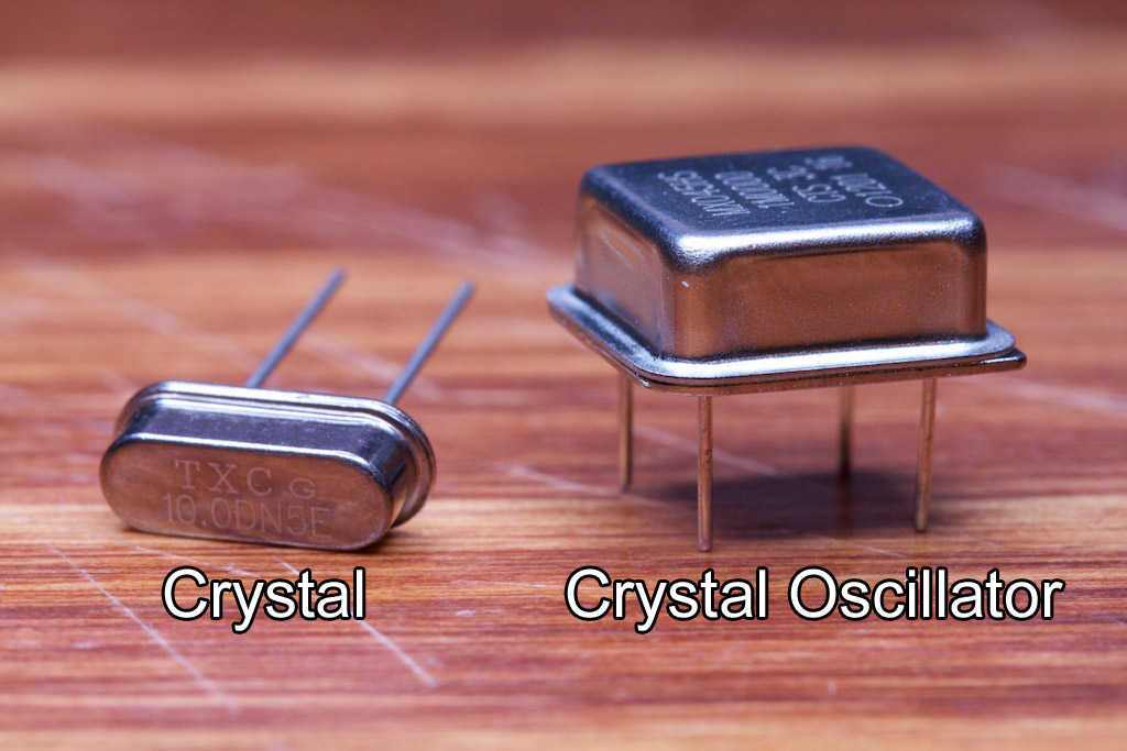
When working with crystals, you have two options.
Bear in mind that some people use these names interchangeably. I choose to differentiate them in this way (as does Digikey, turns out).
The device on the right is a fair bit bulkier because in addition to the piece of quartz, it also contains all of the circuitry needed to get the quartz to resonate. When provided with 5V and GND, a crystal oscillator will simply output a 5V square wave at its rated frequency (the fourth pin is a no-connect).
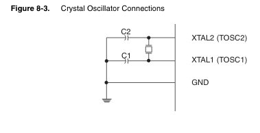
The device on the left on the other hand needs a little bit more babying. Looking at page 31 of the ATMega48a (23MB PDF), you’ll see this diagram:
The little square thing between the two micro controller pins is the crystal. In order to work, this crystal requires some additional “biasing capacitors”. The values of these caps are determined by a table on the next page of the datasheet:
This is the table for low-power crystals. There’s another for “full swing” crystals farther down.
The values of these capacitors are very important. Having the wrong capacitance will cause the clock’s frequency to vary ever so slightly. I dealt with this problem a few years ago when I was working on my wristwatch (which I’m still “working on”). Because the table was only asking for a number of picofarads, the parasitic capacitance in the breadboard became a problem. I ended up using a high precision LCR meter and twisting two pieces of wire together to make a capacitor that I could very finely tune.
A lot of that process was guess-and-check. In fact, through my research for this experiment, I learned that a lot of professionally made clocks are “guess and check” as well. The designers will often make a few iterations of the design to get the clock crystal ticking accurately. They sometimes even resort to fixing the problem in software by having the clock automatically set itself a few milliseconds fast or slow each day to compensate for predictable variations. Some of the more sophisticated clocks even take into account ambient temperature to predict how far they will drift.
Either way, while a crystal is much much more accurate than an RC oscillator, a lot of work needs to be done to make it accurate enough for a clock. Because of all of this, I decided to go with the 1MHz crystal oscillator which I happened to have lying around.
Still concerned that this clock might not be accurate, I quickly set up an short experiment using the 1MHz clock. I set up a micro controller to keep a count of seconds in binary on the LED bank. This count would reset to zero after 59. I then went out and purchased a cheap digital watch.
Jeez, is it really that late?
One of my base assumptions for this experiment is that this watch is accurate. I think this is a fairly safe assumption given that a wristwatch is a dedicated time-telling device that at some point during its design process was probably tweaked with the assistance of a much more accurate clock like an atomic clock. Also a fun fact: although I wasn’t wearing it during the experiment, a lot of wristwatches are tuned with the assumption that their crystals’ temperatures will be regulated fairly consistently by the users’ body temperature.
When I got it home, I synchronized its chrono timer function with the binary output on the LEDs manually. After an hour, I found both clocks to still be visibly synchronized. Of course, an hour isn’t a lot of time for the clocks to drift apart. Because of this, I decided to keep the digital watch synchronized with the experiment for the length of its run. If by the end of the experiment, the binary LED output was still synchronized with the wristwatch, I could assume that the crystal remained a “perfect” time base and measured the 60Hz signal fairly.
RS-232
I used the same RS-232 interface board that I built for my windshield wiper project. This board was originally intended to interface between RS-485 and RS-232 (as pictured above), but I simply bypassed the RS-485 section for this experiment and connected the rest directly to my micro controller.
issues
Originally, this experiment was performed with a single micro controller using the 1MHz clock as its system clock. I set up a software timer (that used the system clock as a time base) on the micro controller that would measure the 60Hz signal coming in. Every second, it would send information about the time lead or lag to my computer over RS-232.
After running the experiment for a while though, I found that the binary LED output and the wristwatch were vastly out of synch. Even in as little as 10 minutes, I could already see the crystal clock lagging behind the wristwatch by a few milliseconds. This is the same clock that worked perfectly when I tested it before.
After scratching my head for a while, I found that the problem was the RS-232 interface. See, serial communication with an AVR requires a few hardware interrupts to be setup. These interrupts happen to have a much higher precedence than the software timer interrupt I was using to keep time.
Basically, every time the micro controller had to send some data to my computer, it would drop everything it was doing and focus primarily on that. This means that it would occasionally completely ignore timekeeping for some portion of every second. Over the course of a few minutes, it had neglected timekeeping so much that it was visibly out of synch with the watch.
After working with a few possible solutions, I found that the only way to make this work with the parts I happened to have on hand was to use two micro controllers. One micro controller did the RS-232 interface and 60Hz measuring while the other simply took in a 1MHz clock signal and output a 1Hz signal. This 1Hz signal left enough time between pulses for the RS-232 interface to do its thing without any interference.
I ended up using a regular crystal for the first micro controller as higher speed was preferred if I was to keep the RS-232 transmissions as short as possible and I only had 4-pin oscillators up to 1MHz. The crystal I used was 10MHz. I did my best with the biasing capacitors, but incredible accuracy would not be necessary for this job as its timer was only measuring a few seconds at a time, and that wouldn’t offer enough time for any drift to take place.
The only other major issue I came across was the (perhaps obvious) discovery that the test will crash if my laptop goes to sleep. This was rather disappointing to see after waking up after a long night’s rest and expecting my test to be 12 hours done.
Software
I’ll spare you the code and leave you with a brief overview. My micro-controller started a timer every time it received an tick from the crystal clock source and stopped that timer after receiving 60 more ticks from the AC source. It then sent the resulting time to a Python script on my computer. I also had it keep track of “lapping” in case one source drifted a full second in front of or behind the other. The program would simply add a second to the time before sending it.
Time was measured in increments of .0001024s
![]()
on a 16 bit timer. The final value (along with “lapping” seconds) was calculated and transmitted as a 16 bit signed integer to my computer. This means that the maximum drift it could measure was (
![]()
![]()
3.35 seconds. At one point in my experiment, the drift exceeded this range, so my +3.35s lag rolled over to a -3.35s lead. This was easy to spot though, and I simply corrected the values on my spreadsheet.
Here’s my whole setup:
Don’t judge me, it was only supposed to be temporary.
Results
The following is a plot showing the experiment over its near-24 hour run.
In this plot, positive values mean that the AC clock was slow while negative values mean it was fast. Also, I noticed that by the end of the experiment, my crystal clock was lagging about .56s behind the wristwatch (verified with a video). Videos taken at various points in the experiment confirmed that this drift was roughly linear, so I accounted for it in the above plot based on it being so.
So this is an interesting plot. One thing it shows for certain is that the AC line is definitely not a steady frequency, but it varies over time. It also shows that the frequency seems to flutter a lot more abruptly during peak hours of the day. At night, it changes much more slowly.
As a possible explanation, I’ve heard that electric utility companies know that many customers depend on that 60Hz to keep their clocks going accurately, but it’s difficult to keep the 60Hz exact when energy demand is fluctuating rapidly.
As a solution, they will adjust the frequency slightly during off-peak hours to compensate for any mishaps during the day.
Ideally, this plot would start and end at zero every day, but my guess is that the required changes can sometimes require more than an entire day to take place. It’s not like they’re in a super big hurry. We’re only talking about a few seconds of inaccuracy, and that isn’t going to kill anyone.
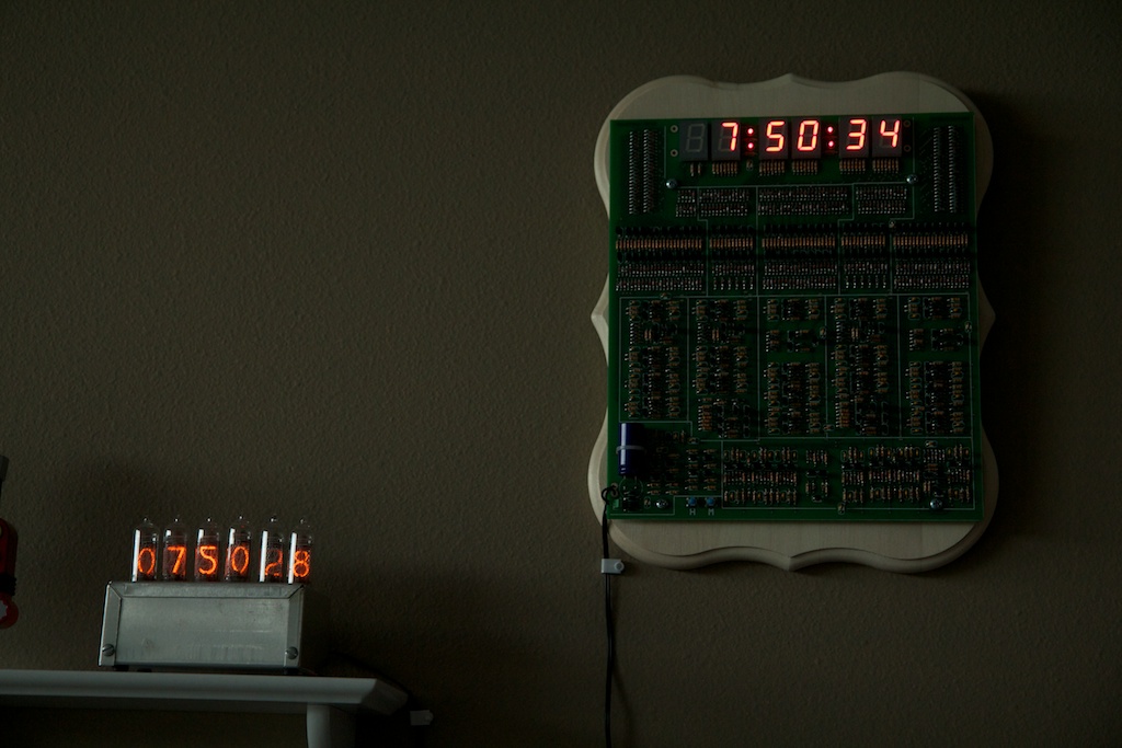
I would really like to run this experiment for a few weeks to see how it goes, but it unfortunately requires too much space on my desk and too much attention from my computer to just run idly in the background. As a possible solution, I’ve been running a much less precise version of this experiment with my nixie tube clock (which uses a crystal oscillator time base) and my transistor clock which now share a wall:
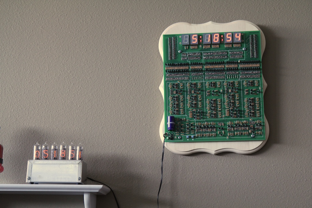
This picture was taken at 5:18pm on Sunday (a day before my experiment started). As you can see, the transistor clock is about 3 seconds slow (note that these photos cannot account for fractions of seconds, so everything should be followed by an “ish”). Moving forward about eight hours, you can see that the transistor clock falls another second behind.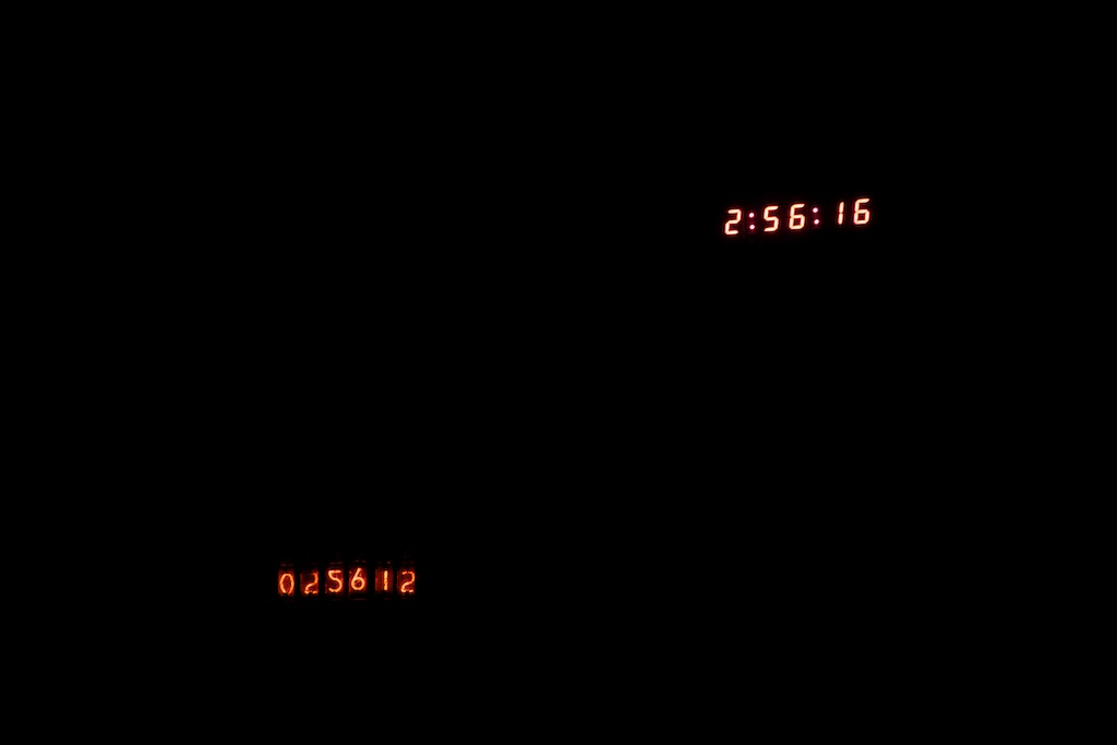
But then another six hours later on Monday morning, it’s only 2 seconds behind:
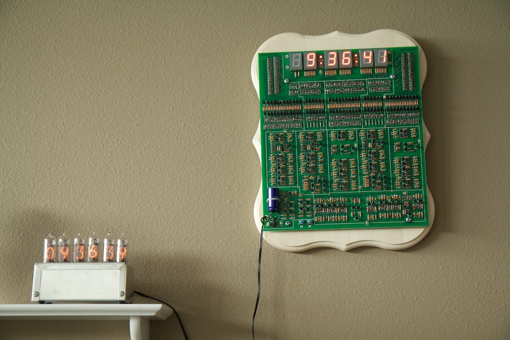
You can even the clocks’ behavior reflected in my test results. The above image was around the peak of the plot:
This might be a little confusing at first because the experiment was taking place entirely separately from my two clocks. It looks like the experiment said that the AC clock (transistor clock) had about a 3 second lag behind its crystal counterpart.
In reality though, the transistor clock was two seconds ahead. We can normalize this value by subtracting five from whatever the plot displays.
So at 7:50PM, the plot shows about a zero lag. That means that our transistor clock should have a “-5 second lag” or a 5 second lead.

And the clocks say?
Boom! Five-ish!
Conclusion
It’ll be interesting to see how these clocks perform over the next few months. I suspect that the electric utility people have a pretty good time source working to keep the 60Hz from drifting, so it’ll be interesting to see if over the long run, the nixie tube clock becomes inaccurate first.
When I set the clocks up, I went through a lot of trouble to get them perfectly synchronized, and since then, I’ve seen them get as far apart as seven seconds, but never any further. They might be a few seconds off one day and then perfectly in time the next. It really makes looking at the clock a much more exciting experience. You never know what you’re going to get!
For more information, you can see a similar experiment here.
More information here.




If you haven’t already seen tvb’s page on mains frequency stability, I highly recommend it: http://leapsecond.com/pages/mains/ It’s pretty interesting how detailed time measurement works!
I have. That’s actually where I got the idea for the experiment. I wish I could run mine for a month like he did! I’ll add a link.
You may find it useful to install a filter between your transformer and your LM311 comparator. Something that insures the comparator won’t trigger multiple times within a 15 to 18 millisecond window. Perhaps one or maybe a cascade of two second order 60 Hz lowpass filters? Or you could copy the precautions made by the designers of the actual transistor clock itself, and use a one-shot multivibrator with a reset time of ~ 8 milliseconds, to completely eliminate any response to input frequencies greater than ~ 80 Hz. A nonlinear filter with brickwall response.
https://ch00ftech.com/wp-content/uploads/2012/06/noisywave.png
Finally, you might want to direct readers to excellent the Wikipedia article on “Utility Frequency”, specifically section 5 “Stability”. Here is the URL: http://en.wikipedia.org/wiki/Utility_frequency#Long-term_stability_and_clock_synchronization
I didn’t mention it, but I sort of made a LPF in software. A few math operations had to take place every time a new tick came in from the AC line. This all happened during an interrupt vector, and I manually cleared the interrupt flag right before returning to the main loop. Basically, if it got a second tick (or a number of ticks) while performing the math, it would ignore them.
Thanks for the wikipedia link. You’re the second person to recommend it. I’ve added a link to the post.
You should read:
http://en.wikipedia.org/wiki/Utility_frequency#Long-term_stability_and_clock_synchronization
Interesting. I added a link at the bottom of the post. Thanks.
Pingback: How’s the 60Hz coming from your wall? - Hack a Day
I implemented an experiment with similar goals: http://blog.blinkenlight.net/experiments/measurements/power-grid-monitor/. However I focused on getting immediate feedback if the frequency is higher or lower than the nominal value. That is: no cool graphics but a somewhat interesting display. And of course somewhat simpler setup.
Thanks for the interesting article! I’ve been recording the grid frequency in New Zealand for almost two years (live meters at http://www.paulmonigatti.com/projects/phd/grid/), but haven’t yet got around to analyzing the time lag. I’ll be sure to put that on the (already rather long) to-do list!
You might want to look up electric network frequency analysis.
its a verry interesting forensics method used for determining the time at which an audio recording was made by looking at the frequency profile of the backround noise and comparing it to recordings of the mains frequency made at known times.
Pingback: Transistor Clock Part 1: Power and Time Base | ch00ftech Industries
Pingback: Bringing a Car Battery Back from the Dead: A Ch00ftech Halloween Tale | ch00ftech Industries