How’s that for an eye-opening title? While you all were watching football this weekend, I made some progress on my wiper driver.
Design
For those of you just joining us, I am trying to build a synchronous motor driver to replace the normal driver for the windshield wiper motor in my car.
If you remember from my other post, the plan here is to place this motor driver inside the engine bay of my car and send commands to it/receive commands from it via RS422 over Ethernet. RS422 is a differential signaling protocol that will help cut out some of the noise present in the normal electrical operation of a car and prevent me from getting data transmission errors.
Relays
The purpose of SW1-SW4 is to allow my driver to sit between the normal driver and the motor. When the micro-controller pulls P15 high, all of the relays will switch over, and my circuit will take the place of the normal driver. When P15 is low (or the circuit is not powered), the normal controller takes over. There are four relays: two for the two speed setting connections and two for the parking switch connections. Ground is connected all the time.
Serial Communication
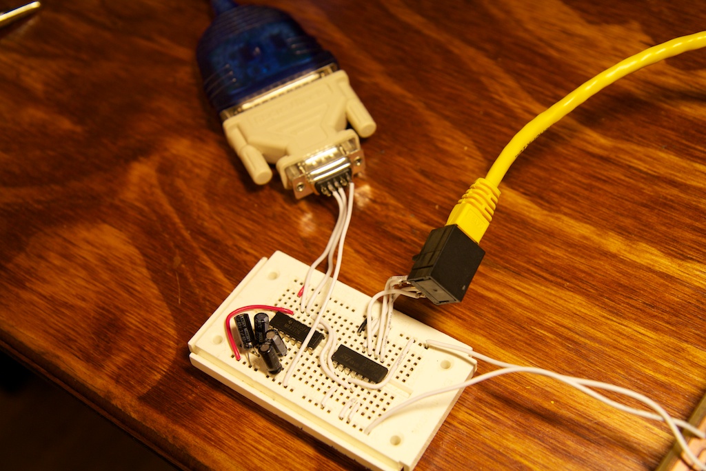
U2 is an RS-422 transceiver. It connects to the AVR’s UART pins allowing me full duplex communication from the AVR to whatever I have controlling it on the other side of the ethernet cable. For the final version, I will have some sort of micro controller setup, but for the time being, I just wanted to connect it to my laptop somehow. To do this, I built a simple circuit on a breadboard as seen here:
There are two chips on this board: a MAX232 which converts the +3V, -3V serial connection coming from my USB serial adapter to TTL logic, and a RS-422 transceiver (ST491ACN) that converts my TTL signal to a differential signal and passes it to my main board over the ethernet cable.
Fet Driver
My plan is to control my motor through Pulse Width Modulating (PWMing) its power source. Because we’re dealing with such high currents, and an inductive load (think of the windings in a motor as an inductor), special considerations have to made to achieve this.
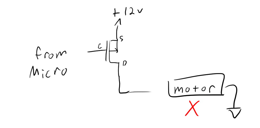
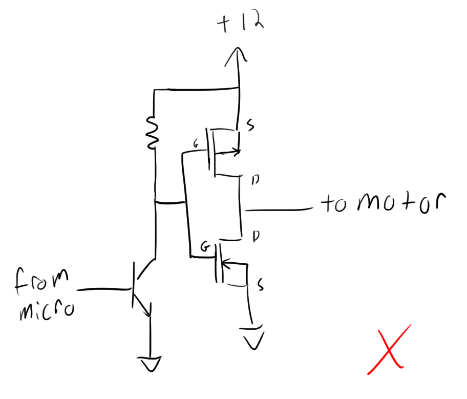
My first inclination would be to use a simple PFET to switch the motor on and off:
Let’s assume that the “From Micro” signal is somehow buffered so that it can output +12V or 0V.
This circuit presents a problem because my motor is like a huge inductor. As soon as my PFET shuts off, my motor’s inductor is going to fight that sudden change in current and induce a huge potential that tries to pull current through the now off FET. This could damage the FET, so we need a better solution:
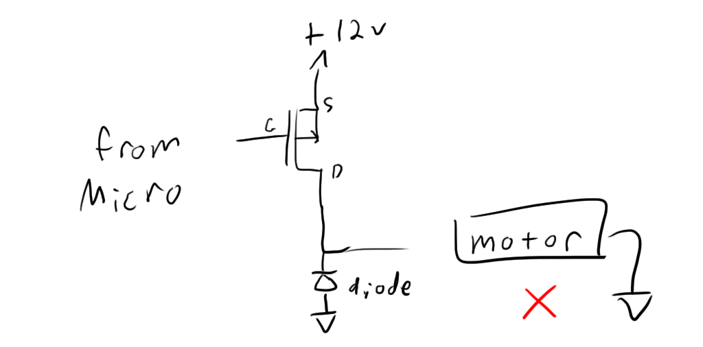
This diode is what you might call a “freewheel diode”. You’ll notice a bunch of them on the terminals of my relays (because the relays are turned on by activating an electromagnet which is an inductive load). The idea is that it doesn’t affect function while the PFET is on, but it allows the motor to safely suck current from ground instead of trying to force it through the PFET while the PFET is off.
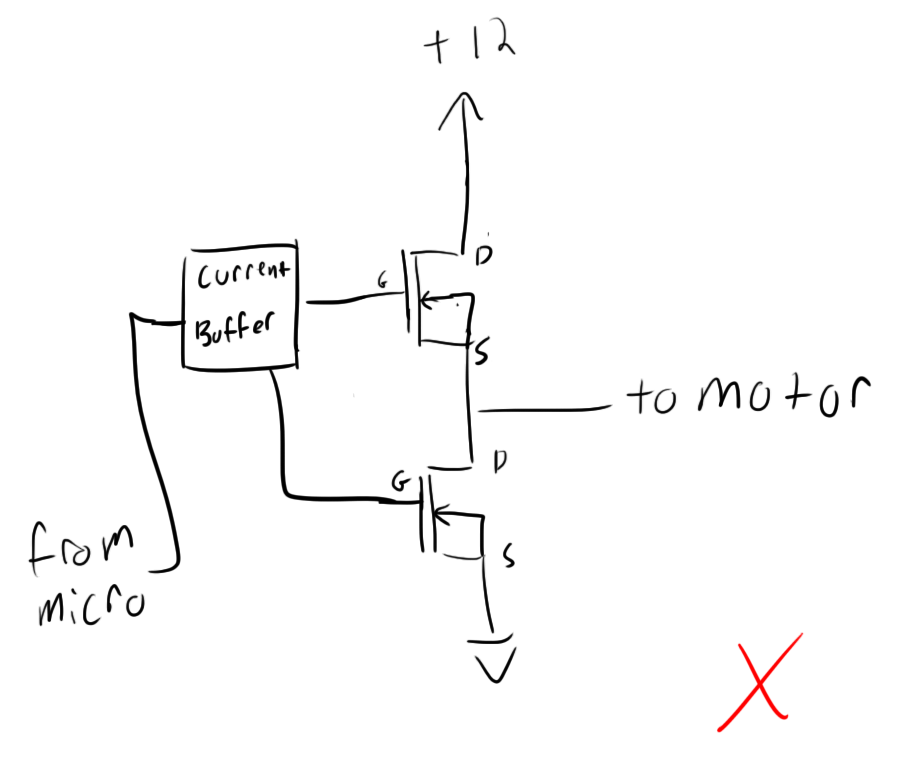
This is a pretty good solution, but it isn’t optimal. Even with good power diodes, you’re still going to have a forward voltage around .3V-.7V or so. When you’re talking about 10Amps of current, a .3V drop is losing you around 3Watts of instantaneous power. While I’m not super concerned about efficiency, I am concerned about my diode being unable to dissipate heat fast enough to keep from melting. Let’s replace that diode instead with an NFET:
The issue with this circuit is a function of how the FETS are being controlled. I previously left out my 12V signal buffer, but decided to leave it in this time to illustrate a problem.
FETs can most simply be though of as digital switches. When they are turned on, they conduct, and when they are turned off, they don’t conduct. In reality, it isn’t quite this simple though. It is possible for a FET to be partially on so that it conducts just a little. This will look in the circuit like a resistor, and when you’re talking about 10A of current, they will dissipate a lot of heat and this could cause issues.
As you switch the FET on and off, you want to really power through this “half-on” state. Every microsecond it spends in this state causes more and more heat to dissipate. Because of this, you really want to yank that gate voltage up and down as quickly as possible. The gate will have some sort of gate capacitance (in my case, around 900pF), so the pull up resistor and that gate capacitance will act like an RC system and slow down the switching action. Slow switch means more time spent “half-on” per switching cycle.
A solution is to use a special chip called a gate driver that is designed to deliver a crap load of current (on the order of 2-2.5Amps) to the gate of the FET. With my FETs, a 2.5Amp current will switch the FET on (bring its gate from 0-12V) in about 1ns. This is a good thing.
Okay, so let’s use a FET driver:
So, this is starting to look good, but there are still some issues. PFETs are typically not as efficient as NFETs. This has to do with quantum physics and the fact that electrons move more readily than “holes” in silicon. A good power P-channel MOSFET is going to cost a lot of money, so let’s ditch that guy and try it with two NFETs:
So, this isn’t going to quite work. An NFET is turned on when its gate potential is at least Vthreshold more volts than its source potential. With this configuration, there is no way to guarantee that with the top side NFET. If the output is very high (for example 10V), the best you could hope for is a 2 volt difference between its source and gate.
To solve this, you need a special kind of FET driver called a “High Side Driver”. This will allow you to drive the high side FET (duh). This is achieved using a capacitor. When the low side driver is switched on, the capacitor charges, and when the high-side driver is switched on, the chip shorts the charged capacitor across the gate and source pins of the high side FET, guaranteeing that it is on.
This method works great except for one caveat, and it’s a small one. Because the high side driver depends on the charge in the capacitor to stay on, it can not stay on indefinitely. Eventually, the charge in the cap will dissipate. All this really means is that you can never attain a duty cycle of 100%. The best you can hope for is 99.9%. This also limits your switching frequency options. The switching frequency must be high enough such that the capacitor does not fully discharge before the end of the switching cycle.
There are a few other considerations here too. You need to be very careful that you never turn both FETs on at the same time. This will cause “shoot through” wherein you basically short your power supply to ground through the FETs. This is very bad. I don’t have to worry about this though, because the FET driver I’m using has integrated protection that makes sure that it switches off one FET before switching on the other.
Construction
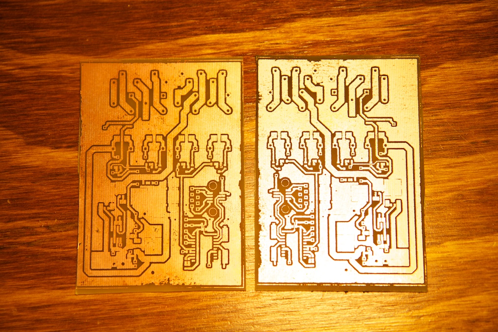
The construction process was not too remarkable except for the fact that I forgot to uncheck the “mirror” option when printing out my etch-resist in my printer:
That was only a moderate setback.
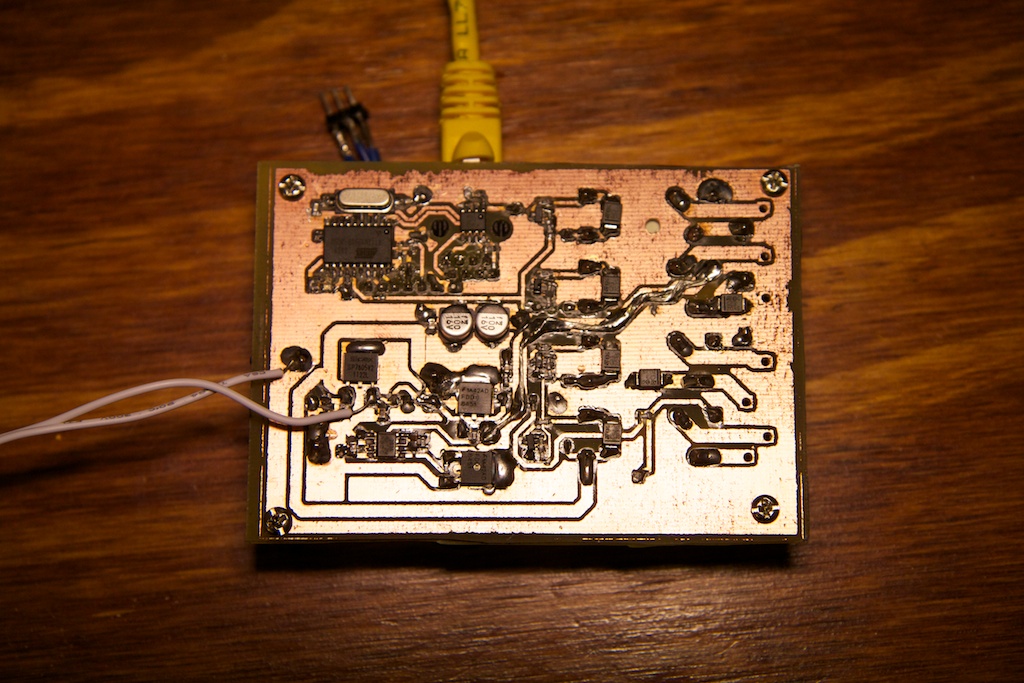
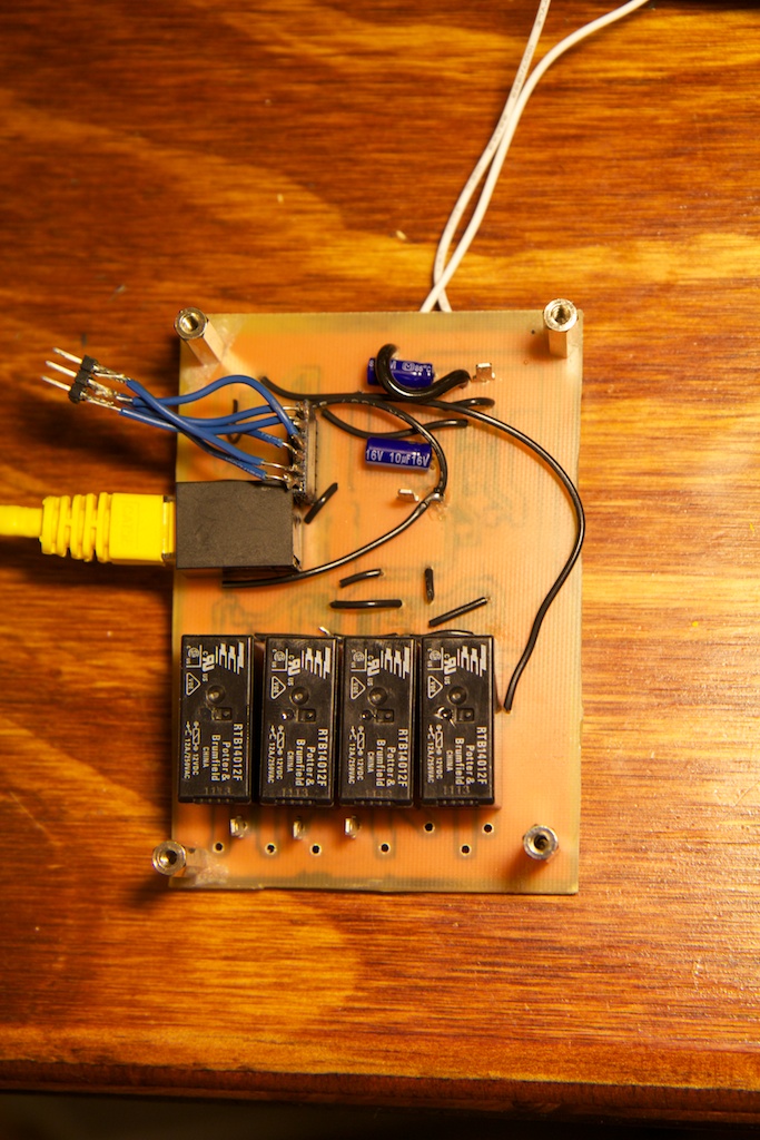
I found some standoffs in one of my many drawers, and decided to use them to make my board sit flat:
Those four black boxes on the bottom are my relays. you’ll also note that I reinforced one of the traces on the top with a piece of stranded wire and a lot of solder. This is the output of my FETs, and I wanted to make sure that there was enough copper to carry 10A of current. This board was made with 1oz. copper which isn’t too thick, so special considerations were made.
The white wires coming off the top are just to power my serial interface breadboard because I was too lazy to find another +5V supply. They’re only there temporarily for testing purposes.
Software
I wrote two pieces of software to make this thing work. The first was a simple Python script that passes values over the serial port to my board. The board was set to accept serial bytes and use them to determine the duty cycle of the FET driver. Furthermore, a byte of “0” switches the relays off and a byte of “1” switches them on. I used the “serial” package in Python. “Struct” allows me to convert Python datatypes to raw binary bytes for transmission.
import serial
import struct
ser = serial.Serial('/dev/tty.usbserial',9600,timeout=10)
print ser.write(chr(0))
while(1): command = raw_input("Input command: ")
if command == 'on':
    ser.write('\x01')
elif command == 'off':
    ser.write('\x00')
elif int(command) <256:
    ser.write(chr(int(command)))
else:
    print 'Invalid command'
The code running on the micro controller wasn’t quite so simple. It needs to properly setup the ATTiny2313’s serial interface as well as its PWM signal generator.
I’ll spare you the code, but here are a few details that might help. I wanted my baud rate to be as close to the standard 9600 as possible. My clock was running at 10Mhz (I made sure to deselect the div8 bit of the lower fuse so that it was actually running at 10Mhz as opposed to 10/8Mhz. I then used the formula on page 113 of the data sheet:
And came up with UBRR = 64 (this is actually 9615 baud, but that’s close enough). I set the low byte of UBRR to 64 and the high byte to 0.
I also selected asynchronous operation, 1 stop bit, no parity, and 8 bit characters. The PWM mode was set to MODE 5 (fast PWM). I also used the ATTiny2313’s waveform generator to set and clear the pin going to the FET driver automatically without any need for software interrupts.
This mode operates by incrementing a counter every clock cycle. This counter goes from 0 to 255. When it reaches 255, the pin is cleared and the counter is reset to zero. When it reaches the predetermined threshold value (sent from my Python script), it sets the pin. In this way, 255 is a 0% duty cycle, and 0 would be 100%. A little counter intuitive, I’ll admit.
Testing
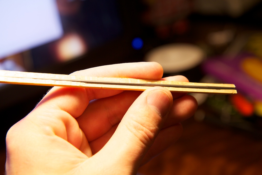
Now the fun part about the pencil. I wanted to test my circuit using some sort of test load. Usually, one might use a power resistor, but I decided to use a pencil instead because they’re cheaper and more fun. The lead from a wooden pencil can be removed fairly easily by splitting the wood using a pair of pliers or wire cutters:
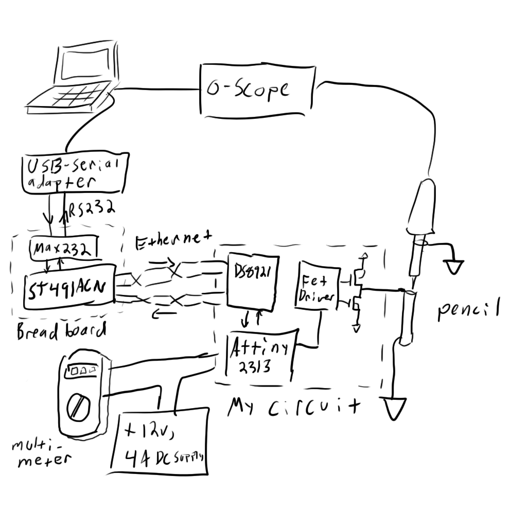
I then configured my circuit according to the following block diagram:
The multimeter is configured to measure Amperes entering my circuit, so it combines the output of the driver with the current required to power its onboard components.
And here’s a video of the test. Stick around to the end to see the lead glow:
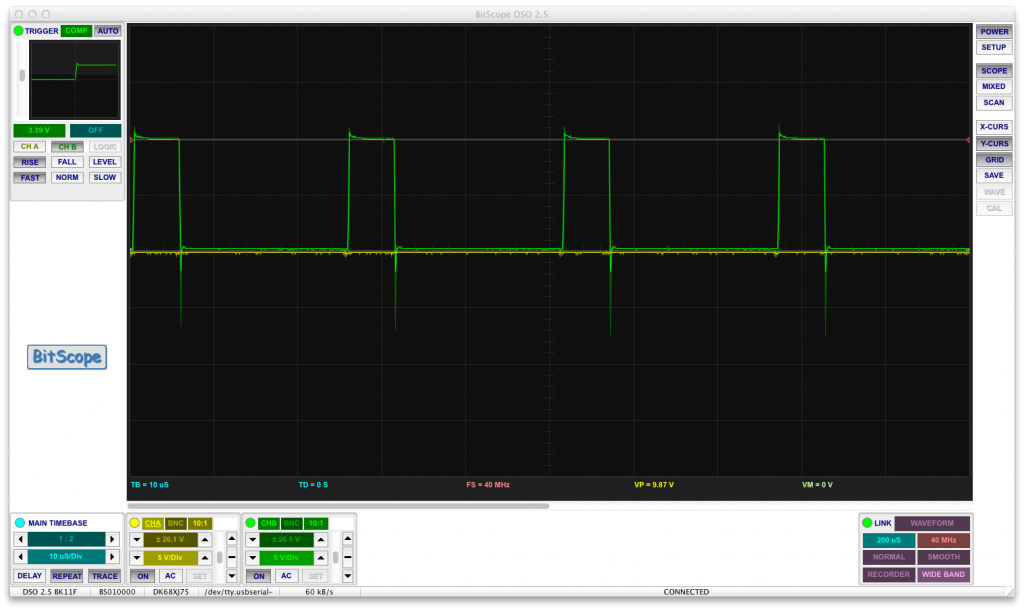
There were a few things that bothered me about that test. The first is that the output waveform of my FETs seemed to not be very square. I pondered this issue for a while until I realized that it had something to do with my scope probes not being configured correctly. After fixing them, the waveform turned out super square:
See?
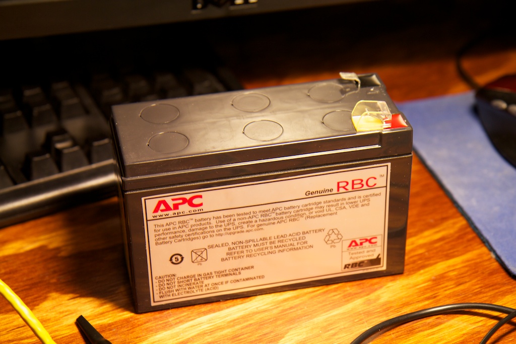
The second is that I was only able to supply a max of 5A because that’s all my 12V, 4A wall supply would put out before it completely switched off the output. For a real test, I was going to need something with some real juice behind it. For this, I turned to my uninterruptible power supply:
Hell. Yes.
This battery is normally used to power a few hundred watts of computer equipment in the event of a power failure. Sure, it only lasts for a few minutes (long enough to safely shut down the equipment connected to it), but I wouldn’t need a lot of time.
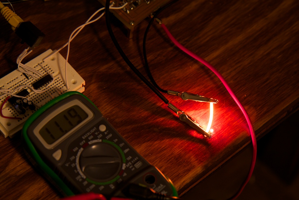
I replaced my 4A supply with this bad boy and really cranked it up. Here it is clocking along at 11.2A:
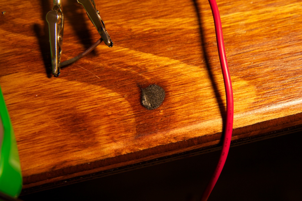
Oh yeah, that little dot of light next to the pencil lead is a flame. I caught my desk on fire:
Whoops.
Results
All in all, the driver appears to be a success. While it was pumping out 11Amps of current, the FETs hardly got warm. If anything, the bypass capacitors on the high side FET got a little toasty. This is because they’re working so hard to stabilize the 12V rail. If the heat becomes a problem, I’ll have to replace them with something that can handle a larger ripple current. I’ll also have to strip and re-finish my table.
Next, I’ll be testing the inputs on the motor driver. These are what the other relays are for, and they will let me read the position of the wiper blades (or at least tell me when they’re parked).
Continue this story here.






Please do not blow yourself up
With all your reducing and oxidizing agents, do you at least have a fire extinguisher in your apt????
Where did you learn so much about analog design in this digital age?
Heh…Four years of college.
Your schematic with the green checkmark, showing two MOSFETS, a bootstrap capacitor, and a high-side gate driver IC (such as the Fairchild FAN73711) … shows a P-channel MOSFET for the pullup, with drain and body connected to +12V. But high-side gate driver ICs are designed to drive N-channel MOSFETs, not P-channels.
This is because N-channel transistors have ~2X higher “surface mobility” than P-channel transistors, so they can get ~2X lower RDSon for the same die size, so they are ~2X cheaper to make than P-channels. (Ignoring fixed costs such as packaging, test, inventory, shipping, etc). Therefore customers would love to design with the cheaper Nchannels ONLY, and omit Pchannels. Voila, the high side driver IC lets customers do exactly that.
Whoops, looks like you caught a mistake. Fixed.
Also, I don’t mean to be rude, but did you actually read this post? I spent basically 50% of the post explaining exactly what you just said.
Haha fucking tell him! This guy just came in here trying to show off his electrical engineering knowledge and you called him on that bullshit! Jesus what the ego is capable of… I know almost nothing about electrical work and studies but have found these posts awesome!
Pingback: Are you sure about that 60Hz? | ch00ftech Industries
Pingback: Bringing a Car Battery Back from the Dead: A Ch00ftech Halloween Tale | ch00ftech Industries
Pingback: Bucking It Up | ch00ftech Industries
As a student, you are likely to face numerous challenges in the course of your college education. However, none of them will match up to the stress that accompanies endless assignments https://www.writemyessays.org/write-my-essays-online/ with strict deadlines and complicated instructions. In such situations, getting help from a fast custom essay writing service will be critical. Don’t let those assignments stress you if you don’t know how to complete them yourself.
This is awesome. Am looking for a high amperage LED Amplifier – ideally something that takes 24v High Amperage and a 24v PWM signal line, and adjusts the about of the input source as a function of the latter.
Ideally something that handle say 1-2kws,