So, I’ve got a little time before I need to start packing, and I thought it would be well used investigating a theory I had about the EL panel. It turns out that my theory was wrong, but that might be a good thing.
So as you might recall, I specifically decided to use a 120V square wave to drive my EL panel instead of a 120V sine wave assuming that it wouldn’t make a difference. Well, there is a very important distinction to be made between these two types of waveforms, and I decided to investigate exactly if and how that disctinction affected my circuit.
AC Voltage
When you say “nine-volt battery”, it’s pretty obvious what you mean. You want a battery with a near-constant 9 volt potential across its two terminals. Measuring direct current voltages is fairly simple. Measuring alternating current is a little harder.
For example, let’s say you have a 120V DC source driving a 1k
![]()
load and want to figure out the amount of power dissipated in the load. You could simply use this formula which is a slight modification of Ohm’s Law:
![]()
![]()
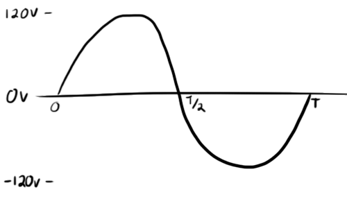
Now, let’s say you try to do the same with a sine wave. How do you define a 120V sine wave? Looking to trigonometry, you might expect something like the following formula:
![]()
Where
![]()
is frequency in radians per second. But this presents an issue when trying to calculate power dissipated into the resistor. You can’t simply use Ohm’s law anymore. Instead, you need to calculate the total dissipated energy over a single cycle and divide by the period. Energy over time is power, and this will be the average power over the whole cycle.
So, let’s start with the voltage waveform:
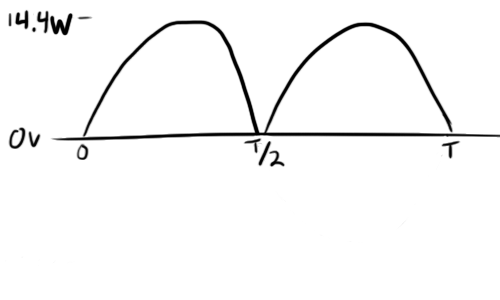
And apply our formula from before to get instantaneous power at any point in the cycle. Note that by squaring the voltage waveform, we are making it always positive.
The next step is to take the integral of this waveform. You can think of taking an integral as taking an area. The area under this curve has the units
![]()
. Because power is definited as
![]()
, the area will give us energy in Joules.
![]()
(go ahead and look this one up)
![Rendered by QuickLaTeX.com \[\Large Energy=\frac{(120V)^2}{1000\Omega}\times (\frac{t}{2}-\frac{sin(2\omega t)}{4\omega}) \bigg|_0^T\]](https://ch00ftech.com/wp-content/ql-cache/quicklatex.com-70399d1005e5ab9b7f8fa9c813d251ee_l3.png)
We can replace all instances of
![]()
with
![]()
and go ahead and solve this one out:
![]()
![]()
Dividing by the period will give us the average power dissipated over the whole cycle.
![]()
![]()
Well, this isn’t right. It looks like a sine wave delivers half the power of a DC signal of equal amplitude. If you still want to get 14.4 Watts out, your knee-jerk reaction might be to double the voltage, but…
![]()
Excellent, now we have twice as much as we need. That doesn’t work either. As you can see, calculating the energy dissipation through a load can be problematic if you measure AC signals by amplitude. Luckily, there’s something better.
RMS
RMS stands for “root-mean-squared” and it’s basically exactly what it sounds like. You take the square root of the mean (average) of the squared signal.
We actually almost did this above. In one of the steps, we had this:
![]()
![]()
is essentially the average of our squared original signal. Let’s tuck the denominator into the exponent:
![]()
Now, if we take the square root of this, we will have the root-mean-square of our voltage signal:
![]()
We can now treat this RMS voltage as a normal DC voltage as far as Ohm’s law is concerned:
![]()
![]()
Which is the same number we got above.
As you can see, once we have the RMS voltage, calculating the power dissipated was a lot simpler. How great would it be if we exclusively used RMS voltage when referring to AC waveforms all together and saved ourselves the math?
That’s what we do.
When you see that your wall adapter runs on 120V AC, that 120V is actually the RMS voltage. The amplitude of that AC waveform will be around 170V, but nobody really cares. RMS isn’t only limited to sine waves though. You can see formulas on the Wikipedia page for lots of different types of waveforms. You’ll see that to convert from amplitude to RMS for a sine wave, all you need to do is divide the amplitude by
![]()
.
You can probably derive most of these formulas yourself. The idea is to look at it from a power dissipation angle. As you can see, the RMS voltage of a DC signal is…very straight forward.
What does this have to do with EL?
Looking at that list of RMS formulae, you’ll see the formula for a square wave. Interestingly, taking the square root of a squared square-wave signal just gives you the absolute value of that signal, so the RMS voltage is the same as the amplitude of the square wave.
This means that a 120V square wave and a 120V sine wave will have drastically different peak voltages. The sine wave might be as high as 170V peak. Again, this doesn’t usually matter because each will dissipate the exact same amount of energy to a conventional load.
But what about an unconventional load? After writing a little more about EL materials, I became concerned that the shape of the waveform might have more to do with panel brightness than one might expect.
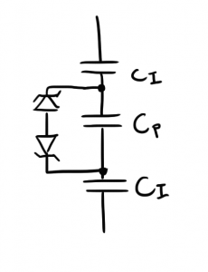
I found that EL materials could be modeled as a series of capacitors and some zener diodes:
The idea is that once you cross the breakdown voltage threshold for the zener models, a small amount of current will flow and charges will shift around on the capacitors. This “electron transport” is what dissipates energy and creates the light that you see. The zeners also help to explain why there is a minimum voltage for the EL panel to light up.
I had a running theory that the model could be further improved with a bunch of parallel capacitor/zener diode arrangements that all had slightly different values. Basically, while some zeners would be conducting, others would not have reached their threshold yet. These inconsistencies would be all mixed together, so while you might not notice splotches of light and dark, the whole panel would appear darker if some of the zeners weren’t conducting.
How high of a voltage is necessary then to make sure that all the zeners conducted? This is the ideal voltage at which to operate the panel as you would be getting the most “bang for your buck” and the highest efficiency. I chose to operate at 120V because that’s what all of the commercial power supplies seemed to use.
The big question is though: Is that 120V? or 120Vrms?
If there were any parts of the panel that required 130V or 150V to light up, a 120Vrms sine wave would be able to light them up as its peak voltage is 170V. A 120V square wave though has a peak of 120V and would not.
I was concerned that I was robbing myself of some brightness because I was driving at too low a peak voltage.
Testing This Theory
I decided to run a test of this theory. I wanted to try driving the panel with a square wave and a sine wave of equal RMS voltage and frequency to see if the sine was was any brighter than the square wave. This proved more difficult that I originally thought it would.
To produce my square wave, I used my original EL panel T-shirt power supply. To produce the sine wave, I built a beefy blocking oscillator power supply with a hand-wound transformer. While I could easily control the frequency of the square wave in software, I found controlling the blocking oscillator to be rather difficult.
Although I can explain how blocking oscillators work, I still have no idea how to set their frequency. By playing around with some parts, I was able to get my blocking oscillator to produce a sine wave as low as 1.6kHz.
Unfortunately, if I increased my square wave generator’s frequency to such levels, the increased current draw caused its voltage rail to sag and the output amplitude would suffer. Because I was only looking to compare the brightness of the panel when connected to each supply, the exact frequency and voltage didn’t matter as long as they were consistent between supplies.
I managed to strike a happy medium at around 1.6kHz and 70V. I ran each supply and took a picture with my SLR locked into the same settings so that equally bright objects would show up as equally bright in the photographs.
Here’s the square wave:
And the sine:
 As you can see, they’re both pretty much the same brightness.
Yup. Pretty darn similar.
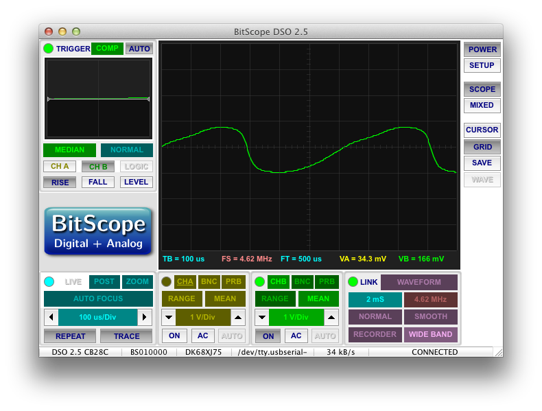
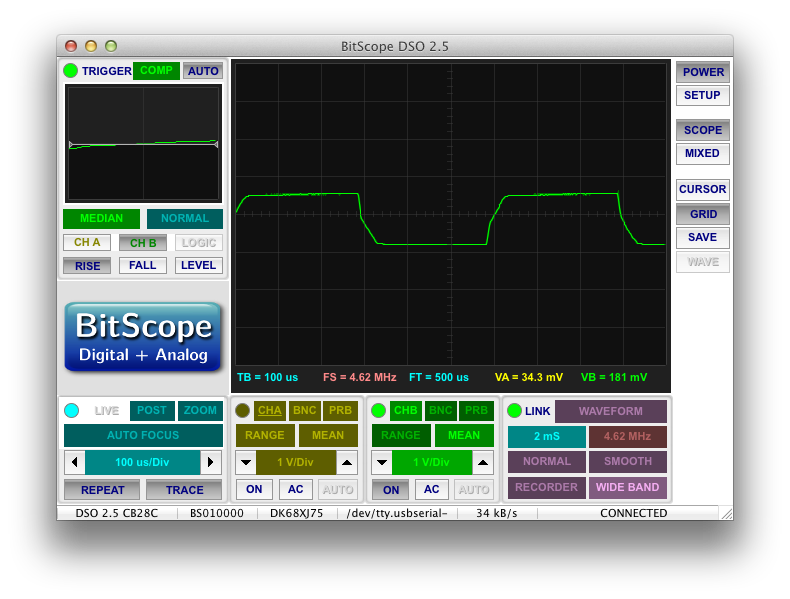
Looking at the waveforms, you can see that the sine wave isn’t exactly a sine wave, but it does have a higher amplitude than the square wave:
Of course, these are measured through a voltage-divider to protect my scope, but the actual peak voltages are 87V and 67V respectively. So you can see that although the “sine” has a peak voltage that is 20V higher than the square, the brightness is not affected.
Conclusion
Now, this wasn’t the most thorough test. If I had the equipment to generate a proper sine wave of arbitrary voltage and output current, I could do a much better job. It’s possible that the 20V difference in peak voltage was not enough to show a significant change in brightness. Given my current track record, you’ll probably see this passage crossed out at some point in the near future when I run another test and realize that my original theory was actually right all along.
Assuming my test results are valid, it appears that even at 70V, the brightness depends only on the frequency and the RMS voltage. This comes as good news. I was concerned I would have to increase my voltage rails up to 170V to get the 120Vrms sine wave I thought I needed. This would also involve trying to find some way to produce a sine wave in software…
The one advantage that a sine wave does offer is possibly a more gradual application of current. Although I’m not certain, I suspect that a sine wave will allow the electron transfer to be spread out over a period of time rather than happening immediately like it does at the transitions of a square wave. Even still, if I redesign my power supply to better handle these dramatic current spikes, it shouldn’t be an issue.
Continue the story here.



Pingback: ch00ftech Industries
Pingback: The Follies of Driving a Capacitive Load with an H-bridge | ch00ftech Industries
Pingback: Reactors to Full Power | ch00ftech Industries
Pingback: Sound Reactive EL Panel Dimmer (for real this time) | ch00ftech Industries