I think LEDs are rapidly becoming the “put a bird on it” of my blog…
Background
Something like two years ago, I had a friend who wore a pair of Christmas light earrings around the holidays. They were the big bulby kind, and they looked so much like the real thing that she was constantly asked if they actually lit up. That got me thinking: how hard would it be to make a pair of Christmas light earrings light up?
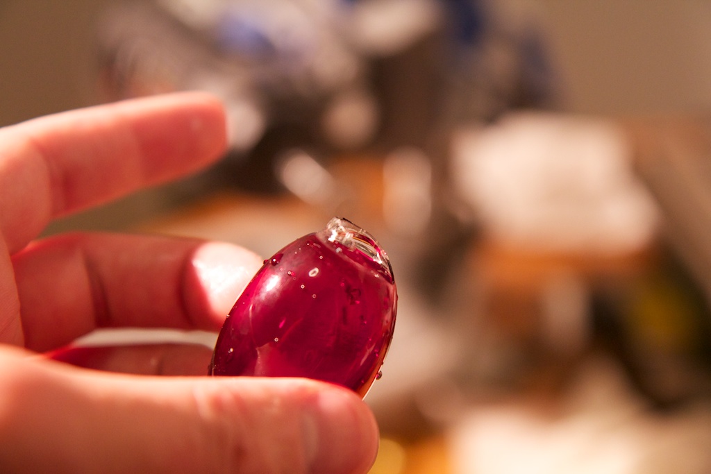
I purchased a few glass Christmas light bulbs and quickly set to work cutting them apart:
I even bought a special diamond wheel for my Dremel tool for the project. The plan was to remove the base from one bulb and the top from another and then reassemble them with a small circuit inside that powered an LED.
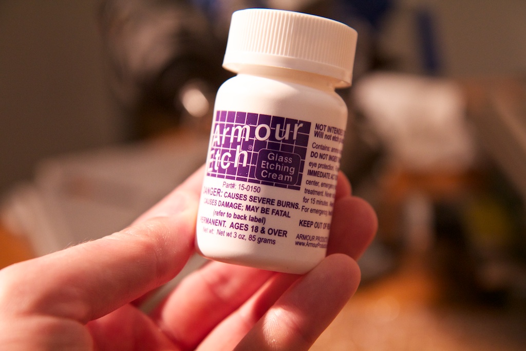
I really wanted to match the even glow of frosted holiday lights which ironically meant that I couldn’t use frosted bulbs. Frosted bulbs are typically coated on the inside with a frosting layer that flakes off very easily. The plan was to use non-frosted bulbs and then frost the inside with some glass etchant:
I even had plans to build a base station that looked like a conventional light socket. Screwing the bulb into the socket would start it charging. At the time, this was achieved using a tilt sensor and…to be honest, I never got a chance to work out the details.
See, no matter how bright of an LED I tucked inside my frosted bulb, I was still unable to achieve that brilliant even glow of an incandescent light. This was partly because of how small of a point light source an LED represents but also because high intensity LEDs tend not to be the diffuse variety. Even scuffing up the LED with sandpaper didn’t help much. I benched the project.
My pre-project shopping spree left me with a dozen Christmas lights in various states of broken and a small collection of very very small lithium polymer batteries:
These things are seriously tiny. They were the smallest I could find online, and they just so happened to fit into the base of a Christmas light. Although their 19mAh of charge is tiny compared to just about any other battery I’ve dealt with, it can still provide enough energy to run an LED for a few hours.
I found them on All-Battery.com, and unfortunately, they’re no longer in stock (unless you want to order 30,000 of them). I found a seller on Alibaba who sells them, but they’re out of stock as well.
So a few weeks ago, I realized that I was sitting on some pretty rare parts and decided that I wanted to finalize my earrings.
Earrings
The goal of this project was to create a pair of tiny light-up earrings that are totally unobtrusive and look and feel more or less like normal earrings. This involved creating the smallest circuit board I’ve ever made and packing it into a tiny case where none of its components would be accessible from the outside.
It’s also the first project I’ve ever made that can recharge its own batteries.
Fancy lights
Before I dive into the details of the battery management and other electrical aspects of the design, I think I should cover the aesthetics and some of the non-electrical design decisions I made along the way.
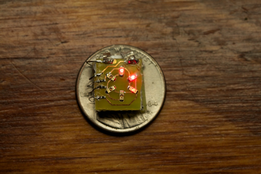
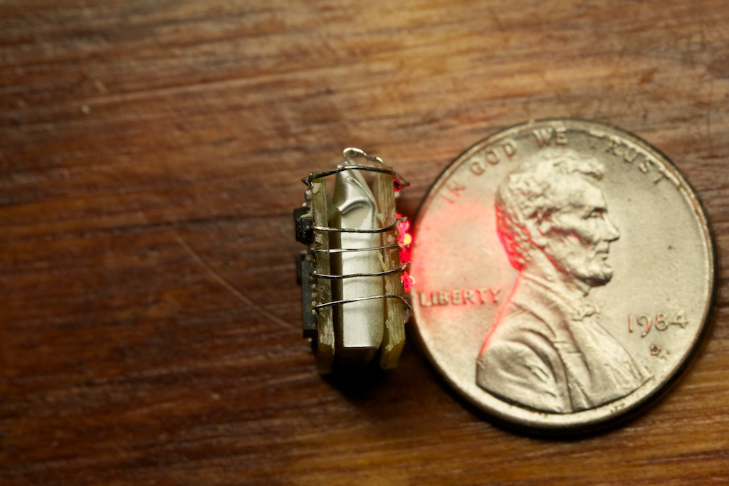
The final circuit and battery combo looks like this:
The six lights on the front are programmed to light up in sequence going around the circle.
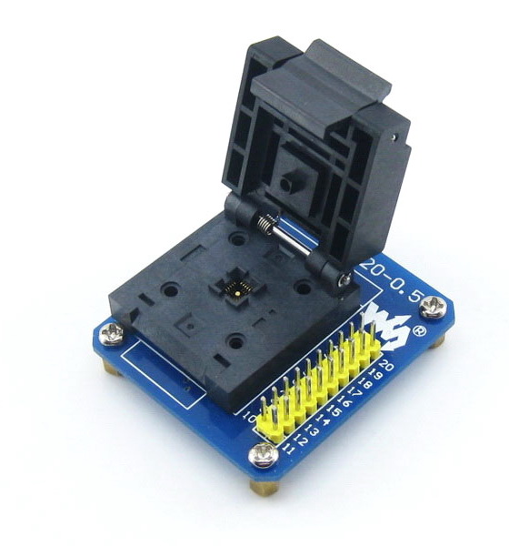
Now, you might be wondering how I developed the firmware for such a tiny platform that doesn’t have so much as a programming header. My original thought was to work out the firmware on a larger development platform and then when I was satisfied, program the parts before soldering them down. Of course, you can’t exactly plug a QTFN part into a breadboard for programming, so that would require something like this:
And these usually cost around $80. I wasn’t quite ready to drop that much dough on something I probably wouldn’t get a whole lot of use out of, so I came up with a different solution.
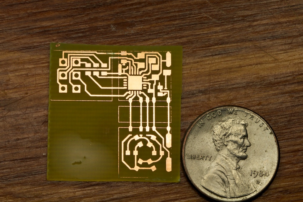
Both of the earrings started their lives like this:
You might already recognize the bottom right portion as the front face. The top right section is the “brain” which houses the microcontroller and just about everything else, and the top left section is the programming header.
The idea was that once I was happy with the firmware, I was able to permanently slice off the programming header and the LED face. The LED section was then reattached with some small wires that wrapped around the battery.
As you can imagine, this process really pushed my fabrication skills to the limit. Many of the traces on this PCB are only 10 thousands of an inch thick. The boards came out much better than I expected. And that was kind of a problem.
When printing a board, you have the option of leaving the dimension layer on or off. The dimension layer shows all the lines that represent the outer edges of the board. Because this layer serves as a method of documentation rather than a representation of anything physical on the board itself like silkscreen or copper, it usually has “zero” thickness which means that the printer makes it as small as possible while still being visible.
Typically, this line is so thin that large portions of it don’t make it to the end of the etching process. This is why I had no qualms with running traces straight through this outline between the three mini-boards.
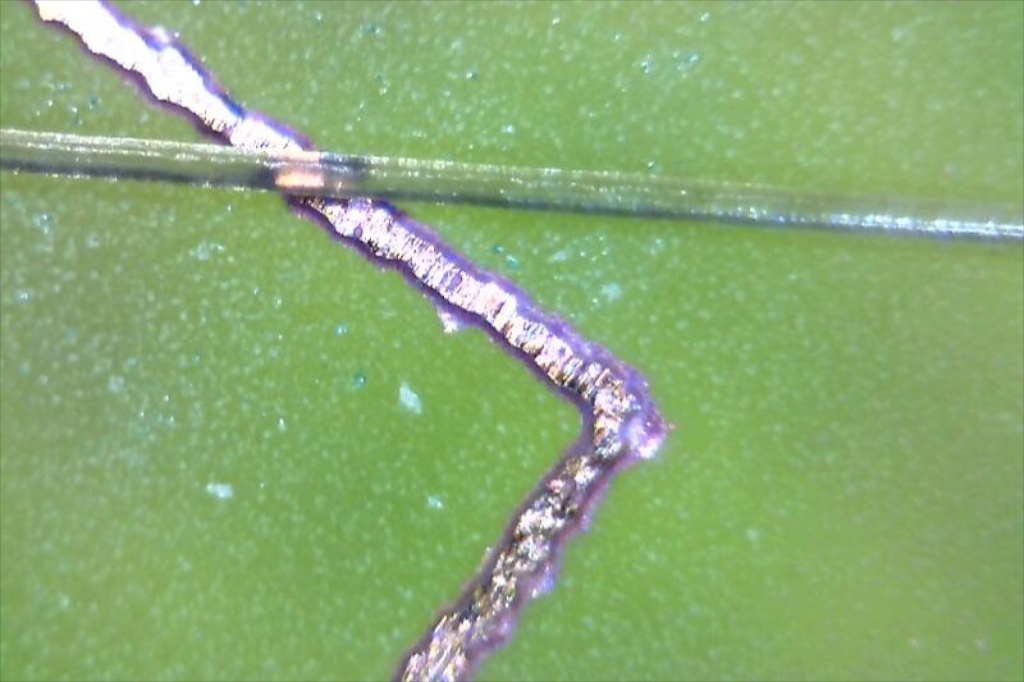
Surprisingly, this time my boards came out so well that these tiny lines of copper were actually shorting out some of my traces! Seriously, look how small these things are:
That clear looking fiber is a piece of hair from my head; I measured its thickness to be 0.003 inches. That’s a seriously tiny trace. I didn’t even have to do anything special to get this result. I just carefully followed my normal printing methods.
Because of their size, these boards were also the first of mine to require 0402 components. Just about all of my boards up to this point have used 0603 components which are 0.06″x0.03″. These new parts are 0.04″x0.02″. They’re small. Small enough that I had to whip out these bad boys just to see what I was doing. For my earlier prototypes, I actually managed to assemble each component by hand with careful use of a pair of tweezers, but I soon switched to solder paste.
One thing I learned this time around is that solder paste doesn’t need nearly as high of a temperature to melt as regular solder does. For a while, I was cranking my hot air rework gun up to 360-400C figuring that it should be around the same temperature as my soldering iron.
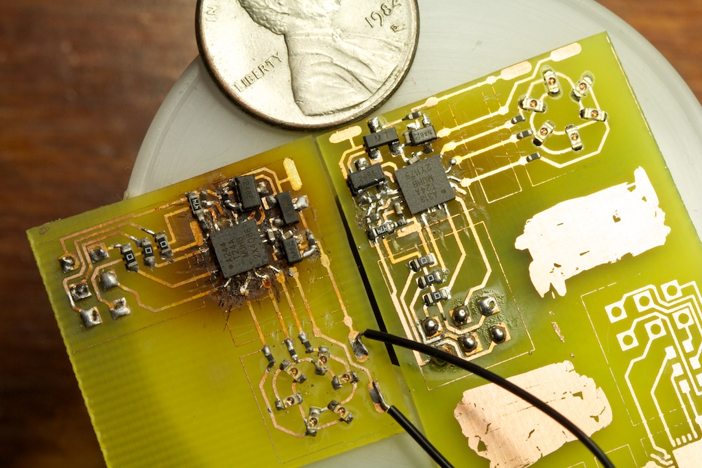
What I later learned is that only 260C or so is required to get solder paste to flow. I bet you can tell which of these two PCBs was made after I figured this out:
Here’s a good closeup of the board:
The open pads on the top and bottom are where the charging pins connect. The battery connections are on the LED board.




Really nice project! Now get these 3D printed and start selling them on Tindie 🙂
I still shy away from using LiPos for the reasons you mentioned. Maybe I should give them a try as well.
A few comments regarding your circuit:
– when measuring the current draw from your circuit, did you account for the voltage divider (I calculated about 8.5 uA)?
– you don’t actually need a voltage divider at all! Using the ADC mux connect VCC as reference and the 1.1 V bandgap as input. From that measurement you can calculate VCC.
– almost did not see this: so you pull low PB0, right? What about the current flowing through R12?
– when in power-down mode you can still wake up the device with the Watchdog interrupt (see http://www.avrfreaks.net/index.php?name=PNphpBB2&file=viewtopic&t=135288). That way you can configure your MCU to only wake up every 8 s.
Great comments!
-The voltage divider certainly contributed to the 0.45mA draw. Also that measurement was taken before I added R12 (I added a note to make this clear).
-That ADC mux trick is brilliant. I’ll definitely use that next time.
-Someone else suggested the WDT as well. I’ve never used one before. I always assumed it ran off the same clock as the application processor (or at least that it drew more current than that). I’ll definitely try that out next time.
Your break off programmer has inspired me to use that design in a wearable project idea that I have. Awesome and Thank You!
Nice project 🙂
One idea that could help storing the earrings in a charged state would be to use a small reed switch between the battery and the rest of the circuit (while keeping the connection to the charger).
I think you could use it to simply cut the power mechanically instead of having a sensor+code to manage the case.
For over-discharge protection when it’s in its box, you would only have the self-discharge effect to worry about, and that would not be a problem as long as the earrings are used at least once every few month.
Yeah, using the 1.1vref for voltage detection works out all right – it’s not 100% accurate, but if you set your threshold high enough, you don’t risk getting near the bottom end of the discharge curve for the LiPo cell. I’ve been fiddling around with adding navigation lights to my RC helicopters now that the sun is setting so early in the evening, and having the lights warn me before the low voltage cutout in the model kicks in is a design goal, and it’s within a few dozen mV of my goal voltage.
(viz: http://jeelabs.org/2012/05/12/improved-vcc-measurement/ although I’m using a different method.)
And white Sculpey is translucent, huh? I’ll have to give my blinkenlights a shot with it. Right now I’m using some HDPE medicine bottles to diffuse the LEDs a bit, but it’s a bit weird looking. Pressing them into Sculpey and baking it up might look a _bit_ nicer…
It’s actually marked as “translucent” Sculpey. I think the white stuff is different.
Neat project. I really like the coulomb graph.
Pingback: LED Earrings #WearableWednesday | electronics-trade blog
Pingback: Community Corner: RGB Stick Man Costumes and Ten More Great Projects from the Past Week in Adafruit’s Community « adafruit industries blog
Pingback: Community Corner: RGB Stick Man Costumes and Ten More Great Projects from the Past Week in Adafruit’s Community | electronics-trade blog
Pingback: Light Up Earrings
do you have a schematic for the charging circuit? Been throwing around an idea that this battery would work well in.
– K-tWizel
Page 4 has the schematic for the charger. You can also download the .zip file at the bottom of page 5 which contains the Eagle schematic files for the earrings and the charger.
Have some master models of the parts 3D printed. Smooth up the surfaces as needed with some primer and sanding. Then make RTV silicone molds for casting in urethane resin.
Smooth-On has a fairly quick setting white that when cast thin enough, light can shine through.
You could make a multiple cavity mold with only one set of 3D printed parts by first making a small mold to cast one set, then cast several sets from that mold to make one or more multi-cavity molds.
Shrinkage of the resin, especially with small sized items like these, is next thing to zero.
This is an awesome project. I’m also doing really small circuits as well. I’m sure you get this a lot but I need help finding a component. I need something that will detect voltage on a battery to about 2.5 volts. Then after hitting 2.5 volts it will direct the power somewhere until the voltage drops back down to about 1.7 volts. Or something similar to that. I just need to find out what kind of component that would be so I can see what there is to offer. thank you
I don’t know of a specific part that can do that. There may be a number of battery management ICs that can be configured to do something like that though. What kind of battery are you dealing with? What’s your application?
Well I’m actually dealing with a capacitor but treating it like a battery, just for energy storage. The application is a small energy harvester that takes in small amounts of energy over a period of about a minute and then dumps that collected energy into a motor or an LED. I found a part that could do the job but I’m going to test it in a few days to see if it’ll work. The LM8364 seems like it’ll work. What do you think? http://www.ti.com/general/docs/lit/getliterature.tsp?literatureNumber=snvs232b&fileType=pdf
Well, that part will certainly detect when the voltage drops below a threshold, but I still don’t quite understand your application. Will this connect to your charging circuit?
Sorry for the long reply. Basically the circuit has a small solar panel* made up of photo diodes. I’m getting a little over 3 volts in normal room light from the solar panel. In parallel with the solar panel I have a 1200uF capacitor as a battery to store the electrical energy made from the solar panel. I want that stored energy dumped into an LED or a small motor once the voltage in the capacitor gets to around 2 volts. I just finished building the circuit just now and it doesn’t work with the LM8364. But the circuit did show that the small solar panel and the capacitor could power an LED for a few msec. Then, i could have also heated the LM8364 to high when I was soldering it. I’ll test the component now to see if it actually functions.
So after testing the LM8364 I figured out the problem. The component basically detects whether there is enough power to run a processor or not. And in return tells the processor to shut down or turn on. For every failure I learn more about what I’m doing.
Look up Microchip TC54 series chips for battery protection, SOT23 package low-voltage detectors basically. Also, using a RGB LED might be an idea.
Pingback: CNC machine, Christmas gifts, and I’m a dope | ch00ftech Industries
Really good design work, unfortunately the Chinese have unlimited “research” funds
and dirt cheap parts and labor. They are selling beautiful LED earrings on the web for 99 cents a pair. Including shipping!!! Sorry Guys!!!
Pingback: CNC machine, Christmas gifts, and I’m a dope » Geko Geek