Time
I’ve built several timekeeping devices before, but the challenge here was to build one where the user doesn’t have to set the time. My logic was that allowing the user to set the time would give them the power to set whichever book they wanted to read, and part of the allure of this clock is how its progress is unstoppable. Besides, making a clock set its own time is harder more fun!
When thinking of a clock that sets its own time, my first thought was one of those fancy SkyMall clocks or wristwatches that set their own time using the radio broadcast from the National Institute of Standards and Technology (NIST). The NIST maintains a 70kW antenna array near Fort Collins, Colorado that broadcasts time and date information on a 60kHz wavelength. A little more research showed that they not only broadcast the time, but also the day of the year and year of the century. Perfect!
I’m no RF engineer (yet), so rather than trying to create a custom 60kHz radio receiver, I shopped around online to see what I could find in the way of 60kHz radio modules. I found a few options, but nothing was in stock, so I did the next best thing:
![Rendered by QuickLaTeX.com 20</a>! And inside: <a href="http://ch00ftech.com/wp-content/uploads/2014/07/clockinside.jpg"><img class="aligncenter size-full wp-image-4439" title="clockinside" src="http://ch00ftech.com/wp-content/uploads/2014/07/clockinside.jpg" alt="" width="1024" height="682" /></a> So what we have here is a PCB with a chip-on-board block epoxy blob that's common for clocks, some buttons, batteries, a speaker, and that little module and coil at the top. The coil is a 60kHz antenna and the module is the radio: <a href="http://ch00ftech.com/wp-content/uploads/2014/07/moduletop.jpg"><img class="aligncenter size-full wp-image-4440" title="moduletop" src="http://ch00ftech.com/wp-content/uploads/2014/07/moduletop.jpg" alt="" width="1024" height="682" /></a> <a href="http://ch00ftech.com/wp-content/uploads/2014/07/modulebottom.jpg"><img class="aligncenter size-full wp-image-4441" title="modulebottom" src="http://ch00ftech.com/wp-content/uploads/2014/07/modulebottom.jpg" alt="" width="1024" height="682" /></a> The radio module had four connections using the familiar color scheme: <table> <tbody> <tr> <td>VDD</td> <td><span style="color: #ff0000;">Red</span></td> </tr> <tr> <td>Power On</td> <td><span style="color: #c0c0c0;">Black</span></td> </tr> <tr> <td>Out</td> <td><span style="color: #00ff00;">Green</span></td> </tr> <tr> <td>GND</td> <td><span style="color: #ffcc00;">Orange</span></td> </tr> </tbody> </table> Uh huh... At least the labeling on the PCB was correct. One other interesting thing about the module is that it apparently takes 1.5V which is less than the 3V provided by the two series AA batteries. The solution was to connect most of the circuit to the two series batteries while the radio only connects to one. <a href="http://ch00ftech.com/wp-content/uploads/2014/07/modulepower.jpg"><img class="aligncenter size-full wp-image-4442" title="modulepower" src="http://ch00ftech.com/wp-content/uploads/2014/07/modulepower.jpg" alt="" width="1024" height="682" /></a> I suppose the radio draws a small enough amount of current so as to not have a significant impact on the battery. And that's only when it's turned on which is (I'm guessing) once per day to keep the clock accurate. After some scope traces, I was able to determine how to operate the radio. VCC and GND connect to 1.5V and ground, and pulling Power On down turns on the radio module. Right away, it will start to receive 60kHz radio and output the demodulated result on the Out pin as a 1.5V square wave. <a href="http://ch00ftech.com/wp-content/uploads/2014/07/goodsignal.png"><img class="aligncenter size-full wp-image-4443" title="goodsignal" src="http://ch00ftech.com/wp-content/uploads/2014/07/goodsignal.png" alt="" width="1475" height="935" /></a> Next up is decoding. Wikipedia has an <a href="http://en.wikipedia.org/wiki/WWVB#Phase_modulated_time_code">excellent description</a> of the time code. The gist is that the 60kHz signal uses a very basic form of amplitude modulation. The signal is either present or not at any particular time. Once per second, a 60kHz pulse is emitted from the radio array. If this pulse is 200ms long, it's a zero, if it's 500ms long, it's a one, and if it's 800ms long, it's a "marker" which is used to separate data types . As you can imagine, this is a very slow form of communication, so you only get a new time stamp once per minute. This is why these clocks will often indicate that they have a signal before they actually set the time because getting the proper time takes at least a full minute. My clock indicated this indeterminate state by flashing the radio icon on the display. It's also convenient that the protocol transmits one bit per second because it synchronizes those bits to actual seconds on the clock. It took me a while to realize that the output of this radio module is inverted (i.e. when the pulse is present, Out is at 0V), but I was able to get a good enough trace with my Saleae to decode a single time stamp. Since markers are sent on seconds 59 and 0, you just need to locate two consecutive markers to figure out where the time stamp starts: <table> <tbody> <tr> <td>Time</td> <td>Pulse Duration</td> <td>Pulse Type</td> <td>Pulse Meaning</td> <td>Result</td> </tr> <tr> <td>0</td> <td>0.79436</td> <td>Marker</td> <td>Start of frame</td> </tr> <tr> <td>1</td> <td>0.19534</td> <td>0</td> <td>40 mins</td> </tr> <tr> <td>1.99</td> <td>0.51098</td> <td>1</td> <td>20 mins</td> </tr> <tr> <td>2.99</td> <td>0.206164</td> <td>0</td> <td>10 mins</td> </tr> <tr> <td>3.99</td> <td>0.215304</td> <td>0</td> <td>Always 0</td> </tr> <tr> <td>4.99</td> <td>0.209944</td> <td>0</td> <td>8 mins</td> </tr> <tr> <td>6</td> <td>0.197688</td> <td>0</td> <td>4 mins</td> </tr> <tr> <td>6.99</td> <td>0.504792</td> <td>1</td> <td>2 mins</td> </tr> <tr> <td>8.01</td> <td>0.49088</td> <td>1</td> <td>1 min</td> </tr> <tr> <td>8.99</td> <td>0.798956</td> <td>Marker</td> <td></td> <td>20+2+1 = 23 minutes after the hour</td> </tr> <tr> <td>9.99</td> <td>0.205956</td> <td>0</td> <td>Always 0</td> </tr> <tr> <td>11</td> <td>0.208472</td> <td>0</td> <td>Always 0</td> </tr> <tr> <td>12</td> <td>0.212956</td> <td>0</td> <td>20 hours</td> </tr> <tr> <td>13</td> <td>0.211552</td> <td>0</td> <td>10 hours</td> </tr> <tr> <td>14</td> <td>0.20858</td> <td>0</td> <td>Always 0</td> </tr> <tr> <td>15</td> <td>0.20668</td> <td>0</td> <td>8 hours</td> </tr> <tr> <td>16</td> <td>0.493796</td> <td>1</td> <td>4 hours</td> </tr> <tr> <td>17</td> <td>0.198572</td> <td>0</td> <td>2 hours</td> </tr> <tr> <td>18</td> <td>0.207872</td> <td>0</td> <td>1 hour</td> </tr> <tr> <td>19</td> <td>0.8092</td> <td>Marker</td> <td></td> <td>4 hours into the day (4am)</td> </tr> <tr> <td>20</td> <td>0.190116</td> <td>0</td> <td>Always 0</td> </tr> <tr> <td>21</td> <td>0.210032</td> <td>0</td> <td>Always 0</td> </tr> <tr> <td>22</td> <td>0.219788</td> <td>0</td> <td>200 days</td> </tr> <tr> <td>23</td> <td>0.200324</td> <td>0</td> <td>100 days</td> </tr> <tr> <td>24</td> <td>0.211836</td> <td>0</td> <td>Always 0</td> </tr> <tr> <td>25</td> <td>0.488684</td> <td>1</td> <td>80 days</td> </tr> <tr> <td>26</td> <td>0.213412</td> <td>0</td> <td>40 days</td> </tr> <tr> <td>27</td> <td>0.212032</td> <td>0</td> <td>20 days</td> </tr> <tr> <td>28</td> <td>0.504496</td> <td>1</td> <td>10 days</td> </tr> <tr> <td>29</td> <td>0.804792</td> <td>Marker</td> </tr> <tr> <td>30</td> <td>0.189864</td> <td>0</td> <td>8 days</td> </tr> <tr> <td>31</td> <td>0.503328</td> <td>1</td> <td>4 days</td> </tr> <tr> <td>32</td> <td>0.505604</td> <td>1</td> <td>2 days</td> </tr> <tr> <td>33</td> <td>0.195972</td> <td>0</td> <td>1 day</td> </tr> <tr> <td>34</td> <td>0.219472</td> <td>0</td> <td>Always 0</td> <td>80+10+4+2 = 96th day of year.</td> </tr> <tr> <td>35</td> <td>0.210808</td> <td>0</td> <td>Always 0</td> </tr> <tr> <td>36</td> <td>0.204724</td> <td>0</td> <td>DUT1 +</td> </tr> <tr> <td>37</td> <td>0.50706</td> <td>1</td> <td>DUT1 -</td> </tr> <tr> <td>38</td> <td>0.212216</td> <td>0</td> <td>DUT1 +</td> </tr> <tr> <td>39</td> <td>0.80608</td> <td>Marker</td> <td></td> <td>DUT1 is negative</td> </tr> <tr> <td>40</td> <td>0.192576</td> <td>0</td> <td>DUT1 0.8</td> </tr> <tr> <td>41</td> <td>0.211388</td> <td>0</td> <td>DUT1 0.4</td> </tr> <tr> <td>42</td> <td>0.508932</td> <td>1</td> <td>DUT1 .2</td> </tr> <tr> <td>43</td> <td>0.197684</td> <td>0</td> <td>DUT1 .1</td> </tr> <tr> <td>44</td> <td>0.21776</td> <td>0</td> <td>Always 0</td> <td>DUT1 is -0.2 seconds</td> </tr> <tr> <td>45</td> <td>0.215488</td> <td>0</td> <td>80 years</td> </tr> <tr> <td>46</td> <td>0.213244</td> <td>0</td> <td>40 years</td> </tr> <tr> <td>47</td> <td>0.208428</td> <td>0</td> <td>20 years</td> </tr> <tr> <td>48</td> <td>0.50354</td> <td>1</td> <td>10 years</td> </tr> <tr> <td>49</td> <td>0.784892</td> <td>Marker</td> </tr> <tr> <td>50</td> <td>0.189896</td> <td>0</td> <td>8 years</td> </tr> <tr> <td>51</td> <td>0.497532</td> <td>1</td> <td>4 years</td> </tr> <tr> <td>52</td> <td>0.198768</td> <td>0</td> <td>2 years</td> </tr> <tr> <td>53</td> <td>0.201924</td> <td>0</td> <td>1 year</td> </tr> <tr> <td>54</td> <td>0.225144</td> <td>0</td> <td>Always 0</td> <td>10+4 = year 14 (2014)</td> </tr> <tr> <td>55</td> <td>0.195084</td> <td>0</td> <td>Leap year</td> </tr> <tr> <td>56</td> <td>0.225728</td> <td>0</td> <td>Leap second at end of month</td> </tr> <tr> <td>57</td> <td>0.498064</td> <td>1</td> <td>DST Value 2</td> </tr> <tr> <td>58</td> <td>0.499896</td> <td>1</td> <td>DST Value 1</td> </tr> <tr> <td>59</td> <td>0.798084</td> <td>Marker</td> <td></td> <td>No leap year/second. DST in effect</td> </tr> </tbody> </table> So, this trace was taken on April 6th, 2014 at 4:23 UTC time (9:23pm on April 5th in Seattle time). This year is not a leap year, and Universal Coordinated Time (set by atomic clocks) is about 0.2 seconds ahead of UT1 time (determined by the rotation of the Earth). This looked like a perfect system, and it would be super easy to coordinate with my books. Connecting to it was a little odd since I needed to interface a 1.5V circuit with a <del>5V</del> 3.3V one. I used an <a href="http://www.fairchildsemi.com/ds/LM/LM317.pdf">LM317</a> programmable voltage regulator. This regulator has a feedback circuit that attempts to keep a reference pin at 1.25V. An appropriate resistor divider on the output can keep this pin at 1.25V when the output is at 1.5V. I started with a 100k<span class="ql-right-eqno"> </span><span class="ql-left-eqno"> </span><img src="https://ch00ftech.com/wp-content/ql-cache/quicklatex.com-5060d7d946cd178c2e892e089190f3ff_l3.png" height="12" width="12" class="ql-img-displayed-equation quicklatex-auto-format" alt="\[\Omega\]" title="Rendered by QuickLaTeX.com"/> and 20k<span class="ql-right-eqno"> </span><span class="ql-left-eqno"> </span><img src="https://ch00ftech.com/wp-content/ql-cache/quicklatex.com-5060d7d946cd178c2e892e089190f3ff_l3.png" height="12" width="12" class="ql-img-displayed-equation quicklatex-auto-format" alt="\[\Omega\]" title="Rendered by QuickLaTeX.com"/> resistor which should reduce the desired 1.5V output by 17% to 1.25V which is perfect for the reference pin. I chose large values to reduce the amount of current and therefore power wasted in the divider, but I found that the reference pin actually draws a bit of current, so my output voltage rose to 4.4V unloaded and 2.7V with a 200<span class="ql-right-eqno"> </span><span class="ql-left-eqno"> </span><img src="https://ch00ftech.com/wp-content/ql-cache/quicklatex.com-5060d7d946cd178c2e892e089190f3ff_l3.png" height="12" width="12" class="ql-img-displayed-equation quicklatex-auto-format" alt="\[\Omega\]" title="Rendered by QuickLaTeX.com"/> load. Dropping the resistors down to 1k<span class="ql-right-eqno"> </span><span class="ql-left-eqno"> </span><img src="https://ch00ftech.com/wp-content/ql-cache/quicklatex.com-5060d7d946cd178c2e892e089190f3ff_l3.png" height="12" width="12" class="ql-img-displayed-equation quicklatex-auto-format" alt="\[\Omega\]" title="Rendered by QuickLaTeX.com"/> and 200<span class="ql-right-eqno"> </span><span class="ql-left-eqno"> </span><img src="https://ch00ftech.com/wp-content/ql-cache/quicklatex.com-5060d7d946cd178c2e892e089190f3ff_l3.png" height="12" width="12" class="ql-img-displayed-equation quicklatex-auto-format" alt="\[\Omega\]" title="Rendered by QuickLaTeX.com"/> solved the problem. On the input side, I used a BJT transistor to buffer the radio's output and raise it to 3.3V. I needed a BJT because I was afraid that 1.5V wouldn't be enough to hit the gate threshold voltage of a FET. A similar circuit brought the Power On signal from the micro controller down to safe levels. The whole thing looked like this: <a href="http://ch00ftech.com/wp-content/uploads/2014/08/radiosubcircuit.png"><img class="aligncenter size-full wp-image-4470" title="radiosubcircuit" src="http://ch00ftech.com/wp-content/uploads/2014/08/radiosubcircuit.png" alt="" width="912" height="838" /></a> With all of this put together, I fired it up and started writing firmware to support the radio when I hit a snag. My radio output signal looked like this: <a href="http://ch00ftech.com/wp-content/uploads/2014/08/badsignal.png"><img class="aligncenter size-full wp-image-4472" title="badsignal" src="http://ch00ftech.com/wp-content/uploads/2014/08/badsignal.png" alt="" width="1475" height="935" /></a> 60kHz is a very low frequency for radio waves, and the signal coming from Fort Collins is extremely weak. As a result, the high frequency and high current electrical signals from my circuit radiated enough stray RF energy to overpower it and confuse the radio module. Placing the module several feet away from the clock fixed this problem, but no matter how I tried to arrange it, there way no way to reasonably attach the radio module that wouldn't leave the signal corrupted. I suppose this is why these modules are typically used in extremely low power clock circuits and even then placed as far away as possible from the rest of the circuit as in the clock I bought. So with a terrestrial radio option no longer available, the next best thing was to look to space. GPS works by estimating the distance between satellites and a target by using the time of flight of radio. This involves each satellite transmitting what are essentially time stamps and the receiver measuring the difference in time between the stamps it receives. These time stamps actually include calendar and date information. Running at around 1.5Ghz, these signals are much easier to isolate than 60kHz. Furthermore, as a more widely used technology, a lot more work has been put into making reliable GPS receivers that are used in a variety of high power products like cars and cellular phones. Googling around, I stumbled across a GPS module on <a href="http://www.adafruit.com/products/790">Adafruit</a>. <a href="http://ch00ftech.com/wp-content/uploads/2014/08/module.jpg"><img class="aligncenter size-full wp-image-4474" title="module" src="http://ch00ftech.com/wp-content/uploads/2014/08/module.jpg" alt="" width="970" height="728" /></a> While they offer a breakout board for this module, I saved a bit by spinning my own. 0.0748 <a title="CNC machine, Christmas gifts, and I'm a dope" href="http://ch00ftech.com/2014/01/20/cnc-machine-christmas-gifts-and-im-a-dope/">Bitcoin</a> and a few days later, and it was in my mailbox. This module contains a totally integrated GPS radio receiver complete with on-board antenna. Communication is over standard serial. With the module in hand, I started working out how to make a breakout board. In addition to simply supplying power and serial communication, there are a few extra features I wanted to include. The device includes an indication LED that is useful for reporting status during debugging. There's also a 1 pulse per second output that could be useful for timekeeping (I ended up not using this). A 3V coin cell battery can be connected to keep the device alive during power off. This helps it more rapidly find satellites when it's powered on again (worst case without this battery is about 15 minutes). Most importantly, the device has a connection for an external antenna. I needed this because I was planning on placing the radio inside a metal enclosure, and I was worried that the GPS signal wouldn't make it inside. External GPS antennas are fairly cheap consumer-grade devices often used for automotive GPS units to add an antenna on the roof. They connect over standard SMA. I <a href="http://www.amazon.com/gp/product/B005RUPU6W/ref=oh_details_o00_s00_i00?ie=UTF8&psc=1">picked one up</a> for](https://ch00ftech.com/wp-content/ql-cache/quicklatex.com-40db5ce85ad728c10a370689eaeb7572_l3.png)
30.
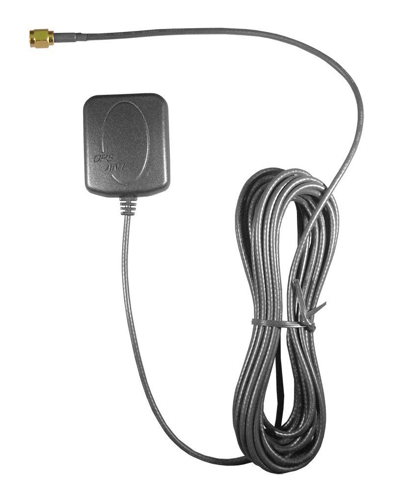
Of course, connecting this antenna required me to build my first ever radio frequency circuit. SCARY!
Not so scary really. I just needed to provide a 50
![]()
trace from the module to the antenna connection. This involves matching the parasitic capacitance and inductance of the signal trace to prevent any reflections along the transmission line from causing problems. Considering how weak satellite GPS signals are coming in, I’m guessing this is pretty critical, but it worked on the first try, so I’ll never know if it was my excellent engineering or the design of the radio’s input circuit that was responsible.
I used an online trace impedance calculator to help design my circuit. I forgot to record the exact values and which calculator I used, but taking measurements from my PCB design file, I used a different calculator to reproduce my results:
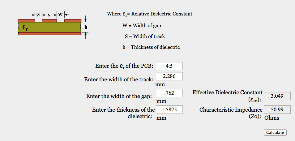 The sizing values are pretty self-explanatory, but the
![]()
is a value I estimated from some search results for “dielectric of FR4”. It wasn’t exactly rocket-science, but it worked. When I do more complicated RF circuits in the future, I’ll have to be more precise, I’m sure.
I took into account other things too such as making the entire bottom of the board a ground plane, and peppering it with vias. I also made sure to keep the RF line as short as possible. The end result looked like this:
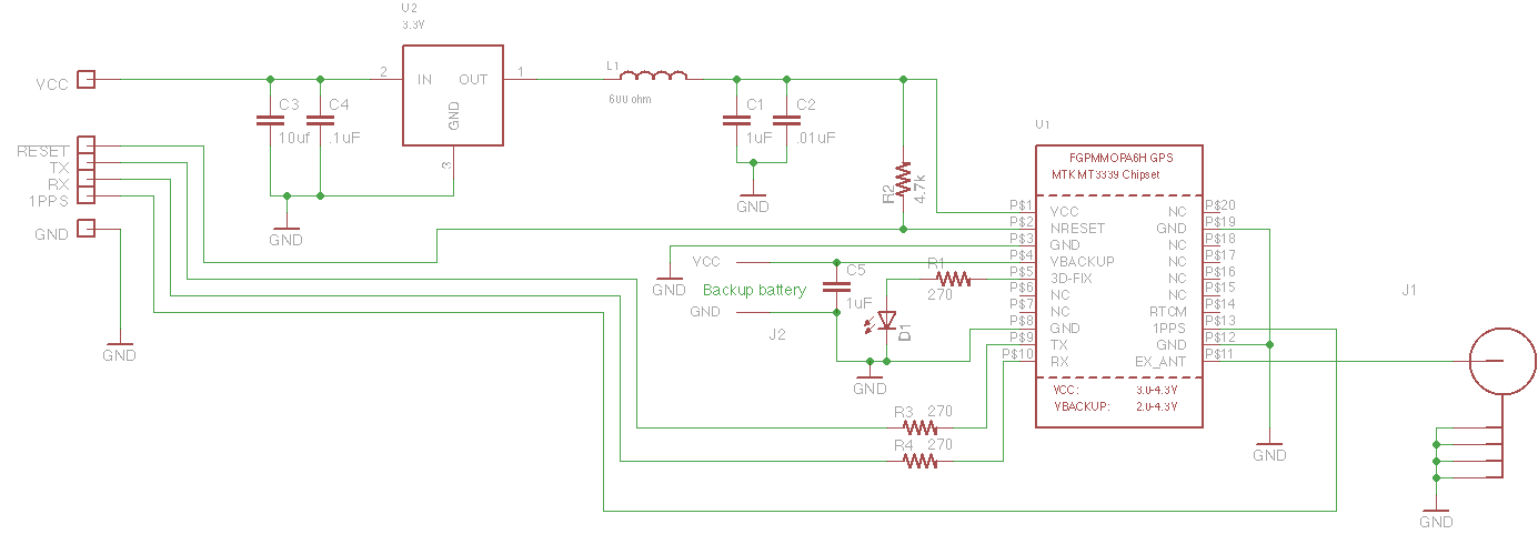
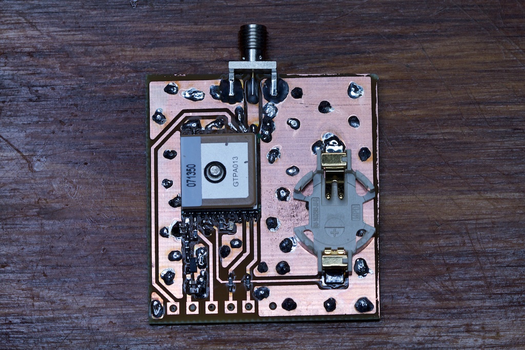 In order to keep the wire connections from shorting to the bottom ground plane, I drilled them out like this:
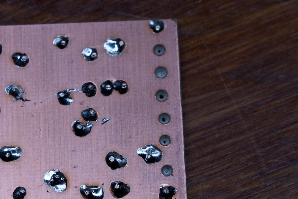
As it turns out, drilling into fiberglass with a general purpose drill bit is an excellent way to dull that drill bit.
The GPS module’s serial command set allows you to configure the frequency with which it reports and what information is in those reports. I set mine to output GPRMC (Recommended Minimum Specific GNSS Sentence) and GPGGA. As the manual specifies, GPRMC provides Day, Month, Year, Hour, Minute, and Second information. GPGGA provides information regarding the quality of the satellite lock. My code waits for the GPGGA data to report “GPS fix” before reading the time/date information from GPRMC.
The returning data looks something like this:
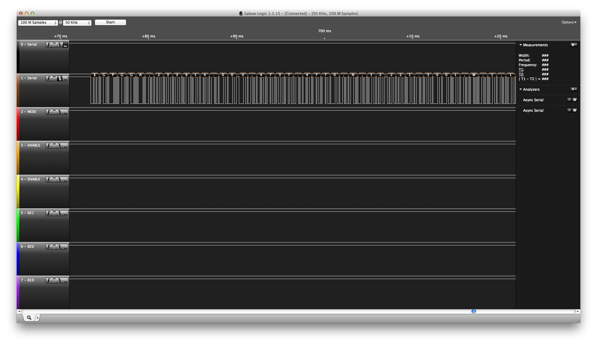
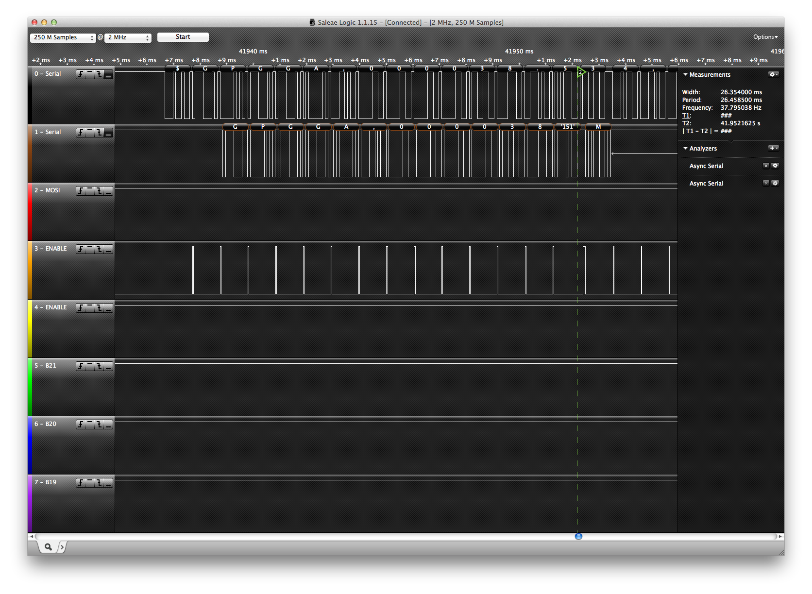
I used the Saleae to capture a single GPRMC packet which looked like this:
GPRMC,034244.000,A,4737.4663,N,12221.3078,W,0.03,244016,060514,,,D*72
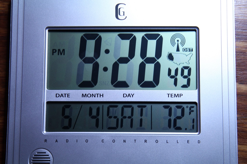
This indicates that the date is currently June 5th, 2014 (060514), and the time is 8:42:44PM in Seattle (034244 UTC). As an added bonus, the GPS location data (47
![]()
37.4663’N 122
![]()
21.3078’W) also checks out:
 I don’t really need position data, but it’s pretty cool how well it works. I might have to use one of these modules again for a future project.
Schematic (again)
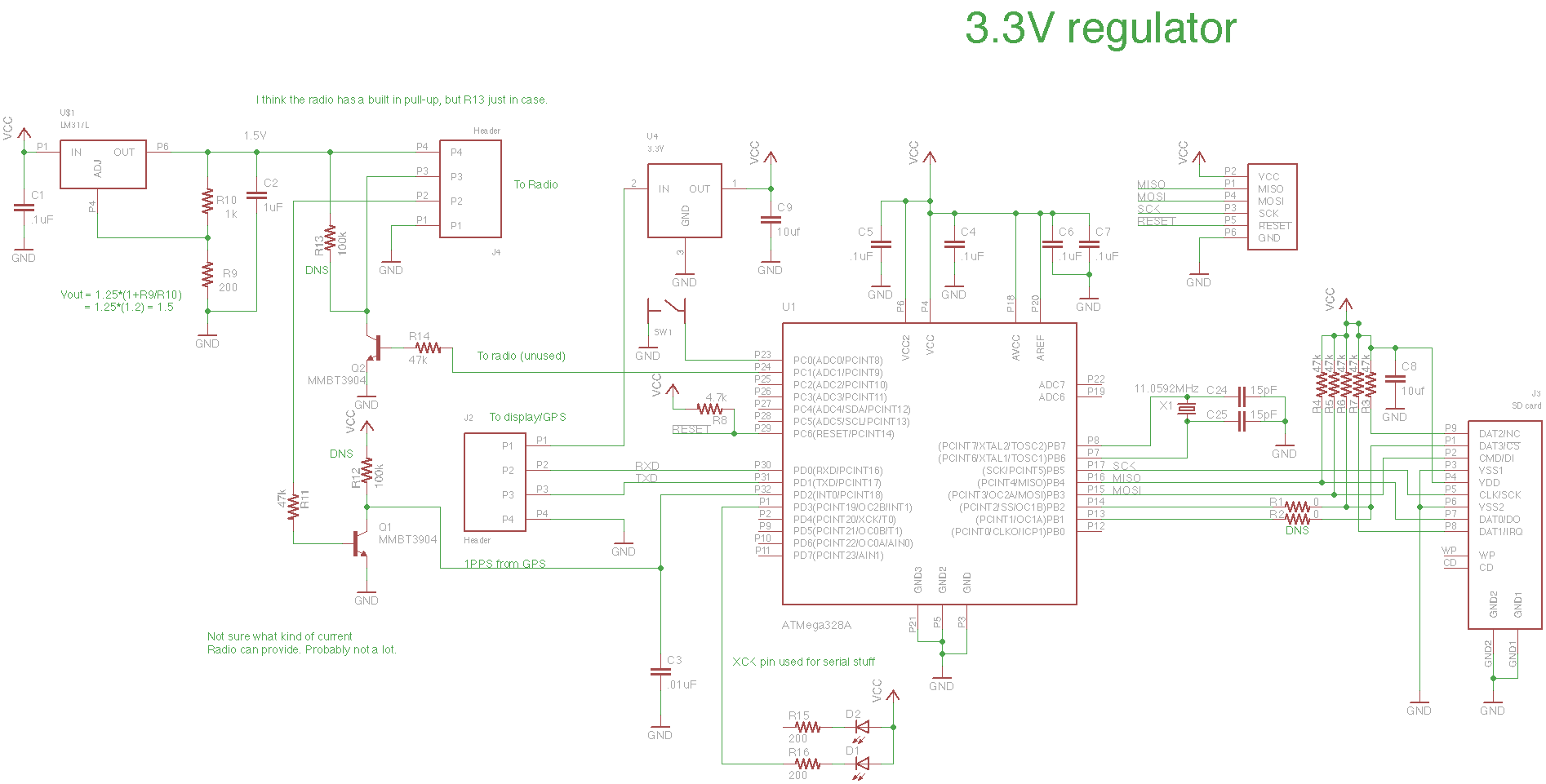
Since there were no more surprises after this point, I’ll go ahead and reveal the schematic:
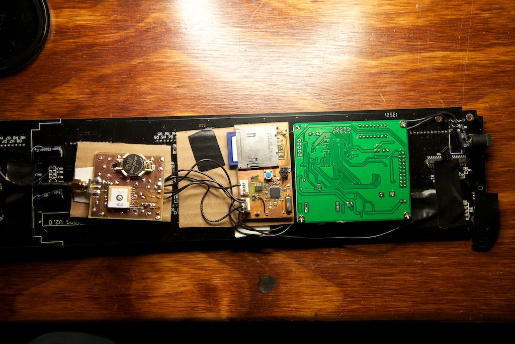
The green thing is the controller built into the display, and the cardboard is a high tech form of insulation.
There are still a bunch of vestigial elements on this schematic. The Output signal from the 60kHz radio module was repurposed to be the 1 Pulse Per Second output of the GPS module which I also didn’t end up using.
The display and GPS module are now both connected over the same serial bus. This is okay because both of these devices require their commands to be prefaced with addresses that are unique to each of them. Furthermore, because only the GPS module sends any kind of response, there’s no need to worry about a race condition where the GPS module and display might try to send messages at the same time. It’s just convenient that both of them accept 9600 baud serial.
That’s not to say I didn’t have any problems.
Serial problems
With the hardware finished, I set about writing some firmware. A few days into this, I noticed that sometimes data packets were getting corrupted when sent from the GPS radio to my AVR.
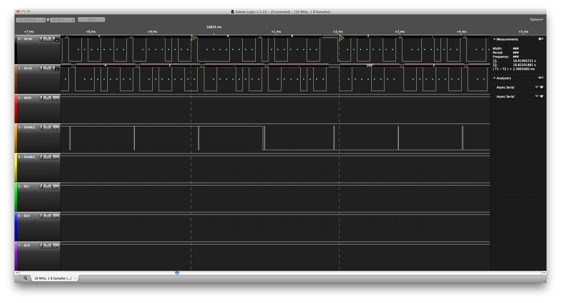
As a temporary fix, I used the internal framing error bit of the AVR to detect when data was coming in corrupt and wrote some code to just ignore it. While this more or less fixed the problem, I wasn’t content to just let it slide without finding a root cause. Here you can see a simple loopback script with a debugging bit indicating where the corrupt byte comes in (‘0’ turns into ‘.’):
I had a number of theories as to what was causing this problem:
- I measured the GPS module transmitting at 9607.69Hz while my AVR transmits at 9600.00Hz. Standard serial starts counting from when the first bit is set, so it’s possible that for long messages, this accumulated error causes bits to be missed. Seemed unlikely though because that’s less than 0.1% error.
- I thought my code might be taking too long to handle incoming data so that it can’t keep up. This was ruled out by some debugging where I established that my code spends a majority of its time in a tight loop waiting for data to come in.
- Noise? I don’t know. I probably had a thousand half-baked theories about what could be going on here, but nothing seemed particularly out of place, and I was going crazy.
One interesting thing I found is that it sometimes randomly did take slightly longer to read an incoming byte even if it was still a much smaller amount of time than the total serial transmit time. You can see this below where the orange trace indicates how long it took to read the incoming byte from a buffer and how that correlates to where the corruption starts.
The actual problem ended up being pretty interesting.
Because I’m lazy, I very rarely write code from scratch. A smart engineer tries to avoid duplicating work, so many good software engineers try to find libraries to do what they want or write their own libraries that they can pull into any future project that has similar requirements.
Unfortunately, I’m not a good software engineer.
I usually start a project by pulling in code from other similar projects. In the case of this project, I was going to use the code from my party lights which used the ATMega328 to communicate over serial, but that project only received serial. It had no code for transmitting it. Instead, I used the code from my beat tracking windshield wipers which maintained two-way communication with the PC controlling them.
What I didn’t seem to notice is that the wiper driver used the ATTiny2313 while my new circuit used the ATMega328. You can see below how my Gutenberg Clock code sort of resembles the Wiper code that it drew from.
Wipers
//config serial
UCSRB = 0b10011000; //Transmitter enable, Receiver Enable, receiver interrupt enable
UCSRC = 0b00000110; //8 bit, asynch, no parity, 1 stop bit
UCSRA = 0b00000000; //Don't double trans speed
UBRRH = 0;
UBRRL = 64; //9600 baud
Gutenberg Clock
//config serial
UCSR0A = 0x00; //no double trans speed
UCSR0B = 0x08; //TX enable
UCSR0C = 0x46; //8 bit, asynch, no parity, 1 stop bit
UBRR0H = 0;
UBRR0L = 71; //9600 baud
For some reason, I switched bit 6 of UCSRnC from a 0 to a 1. I’m not entirely certain why I did this, but if I had to guess, I’d say it has something to do with misinterpreting the changes added to this register in the ATMega328 to support more USART features.
I also could have temporarily mixed up “synchronous” and “asynchronous”. Asynchronous means that no clock pin is required, but counter-intuitively, it requires receiving and transmitting parties to be more “in synch”. That always confuses me.
Regardless of why I did this, the implications were pretty interesting.
I accidentally placed my UART into synchronous mode. This means that my AVR was providing a data clock that nobody was reading. What’s confusing is how well this actually worked. Transmission from the AVR was completely unaffected.
Asynchronous serial requires the receiving party to start a timer when the first bit gets set and then check back on the line at a regular interval (9600Hz) to see the following bits. This mode of communication can be severely impacted by unexpected delays between bits. Synchronous communication adds the clock pin which makes it more robust as the receiving party can be told by the sending party when the bit is ready and should be read.
In my case, I was lucky in that there were no unexpected delays between bits sent from the AVR. Although it isn’t required for synchronous communication, the AVR maintained a solid 9600kHz transmit rate with no delays. Ignoring the clock line, this looked exactly like a standard 9600 baud serial transmission. This worked 100% of the time.
This wasn’t the case on the receiving end though. As I said before, asynchronous communication requires a timer to be started when the first bit arrives. Because the AVR was under the impression that its clock pin was providing the timing, it read the incoming bits on its own schedule.
For the most part, this actually worked! Since both devices had such well tuned transmit/receive clocks, as long as the AVR started reading somewhere between the clock edges of the incoming signal, it would continue to do so without problems. Furthermore, since the baud rate is so slow compared to the rise and fall time of the signal, the bits are valid for a majority of the time.
Every once in a while though, there will be some small delay or change in clock speed that can make a data stream that was near a clock edge pass it and corrupt a bit. That’s where my problem was.
So, at 3AM (yes, Seattle time this time), I fixed the UCSRnC byte and had no more problems. It wasn’t entirely a waste of time though. I learned a lot about how the AVR’s USARTs work during my investigation and used the Frame Error detector for the first time.



Pingback: Gutenberg Clock Keeps Time by Reading Books
Pingback: Gutenberg Clock Keeps Time by Reading Books - Tech key | Techzone | Tech data
Pingback: Gutenberg Clock Keeps Time by Reading Books | Ad Pub
Pingback: Gutenberg Clock Keeps Time by Reading Books | Hack The Planet
Pingback: Nerdcore › Gutenberg Clock reads a Public Domain Library
Pingback: Auteursrechtvrije Gutenbergbibliotheek leest als een klok | Rafelranden
If you are interested in porting the Gutenberg clock to my Wise Clock 4, I could send you a kit (you would need to buy the displays from Sure Electronics). In the end, you could have a device with ATmega1284, SD card, GPS, bluetooth and 128×16 tri-color display,
Pingback: PrintSnap Instant Camera | ch00ftech Industries
Pingback: Electrical Hell and the apocalypse survival external phone battery | ch00ftech Industries
2lnmst6u
zfi5l0
io70li
el0w07
jijzb0
hhmsxv
jumrg4
q59fzb
9gl6tt
bv9yxq
xg87xp
umtdf1
63ghlk
5qgq22
p4v4ys
ialscr