So I’ve got a project coming up (that may have something to do with this tweet) that will require a few LED matrix displays. I found a suitable candidate online and ordered one to play around with. Since I already had the display, I thought it’d be fun to run it through the paces and build a little circuit out of it using some parts I had lying around.
What I came up with is the “Laser Doodler.”
Concept
So when this display arrived in the mail, I wanted something to do with it so I could get accustomed to the pinout and LED intensity. I thought it would be fun to create a simple display that can be “drawn on” with a light source. An LED would work, but using a laser allows you to doodle from across the room if your hand is steady enough.
Sensor Matrix
In order to accomplish this, the display needed to alternate between being a display and being a sensor. During its sensor stage, it records where the laser dot is located, and during its display stage, it lights up the LED associated with the laser dot’s position. But how do you make an LED matrix into a sensor matrix?
A while back, I wrote an article about using LEDs as light sensors. If you want to have any idea what’s going on in this post, I highly suggest you read that one first. In short, when you reverse bias an LED, it will pass a small amount of current that is proportional to the intensity of the incident light that is equal or greater in frequency than the light the LED normally emits (i.e. green LEDs can’t detect red light). Because small units of current are difficult to measure directly, I instead allowed that current to charge a very small capacitor and timed how long it took to charge up. Higher current -> faster charge.
That demonstration was an incredibly quick and dirty hack, and it only worked for a single LED. In order to make an entire display function, I needed to multiply that by 64. Before getting into how this is done, let’s get to know our display a little better.
Displaying
The display is a BL-M12A883DUG-11 which I found on Adafruit for $7. The display has 64 red and 64 green LEDs so you get a total of three colors available (amber if you turn red and green on at the same time).
The device has two parallel rows of 12 pins each. The pin pitch is .1″ as usual, but for some reason, the two rows are just .05″ short of half an inch apart. Sort of odd. I had to bend the pins slightly to fit them in my breadboard.
You might be wondering how the heck you drive 64×2 LEDs off of just 24 pins. The answer is: you don’t.
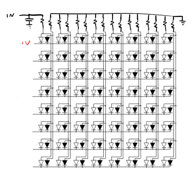
This design only allows you to drive one row of the display (green and red together) at a time. Take a look at page two of the datasheet. You’ll note two different schematics. This display is the “A” model, so make sure you only look at the schematic on the left (mixing those two up cost me an hour of design time).
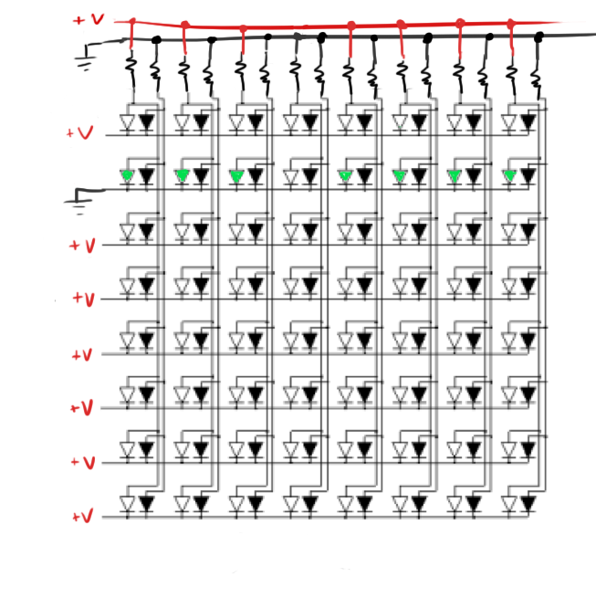
You’ll see that all of the cathodes of a single row of LEDs are tied together. Once the cathodes for a row are held low (and the rest of the rows are held high), the pins along the columns allow you to choose which LEDs to illuminate specifically. Any column pin that is high at this time will cause its associated LED for that row to light up.
 The resistors were added to act as current limiting resistors for the LEDs.
Once these LEDs have been lit for a while, the cathode for that row can be pulled high shutting off all the LEDs in the row. Then the next cathode down is held low and the process continues.
If you scan through the rows like this fast enough, it will appear that all rows are lit up simultaneously. Of course, you have to be careful to light up each row for an equal amount of time or you’ll end up with some rows looking brighter than others.
This process requires you to have 24 pins that can be individually addressed. Unfortunately, the ATmega48a micro controller that I used doesn’t have quite enough output pins. To make it work, I first connected the cathodes to the 8 pins of Port D and the green anodes to the pins of Port B with the exception of pin 6. Pin 6 of Port B can also be used as an external oscillator pin which means that it has slightly weakened drive capabilities when configured as an I/O pin. This would cause one column of my display to be slightly dimmer than the rest. To solve this, I used a pin of Port C instead. I made sure to connect the pins in the right order so that pin 0 of Port D connected to the first column of LEDs. This made my software a little bit simpler.
With the green LEDs accounted for, I moved on to the red. I connected the red LED anodes to the output pins of a 74HCT573 Octal Latch that I had lying around. An octal latch has 8 inputs and 8 outputs. When the chip’s latch enable pin is held high, it connects its 8 inputs to its 8 outputs. When the pin is subsequently held low, it locks the output pins in their current orientation. This allows you to change the input pins without affecting the output.
So with my 8 output pins connected to my LEDs, I connected the 8 input pins to Port B. This effectively lets me “double up” on my Port B output capabilities. In order to display red and green on the LEDs, I had to output the pattern for the red LEDs, set the latch, and then set the output for the green LEDs.
To prevent any weird and unsightly glitches during this process, I set all of the Port D pins high so no light would come out of the display.
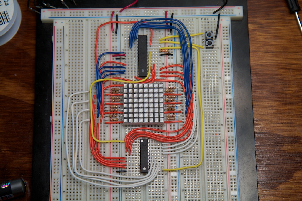
This is a diagram of the connections made for one pixel. The wires are color coded to the wires I used on my breadboard. The “LE” line is “Latch Enable” and is connected to one of the pins of Port C.
So that’s the easy part. Now the question is how to make the display into a sensor.
Sensing
This trick takes advantage of the fact that the Port D and Port B pins can be used as inputs or outputs. When set as an input, a pin will not be driven to either ground nor +V (assuming the internal pull up resistor is turned off). It will be loosely connected to ground though through a nearly infinite resistance, but for our purposes, we can say that it’s “floating”. Its voltage will be read by the micro controller, and as soon as it passes a threshold (in this case 3V assuming the chip is powered from 5V), the software on the micro controller will read it as a logical “1”. For more details, you should read the light-sensor article I linked above.
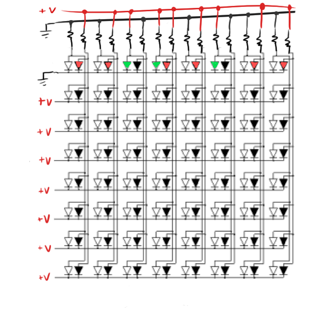
The real tricky part is selecting the pins so that only one LED sensor is read. Let’s start by reading the pixel in the top left corner.
In this state, all of the LEDs in the top row are reverse-biased, and are all already passing a small amount of current to ground (depending on how much light is hitting them).
All of the other rows are set to high-impedance inputs. I won’t be reading them, but I do need them to be completely disconnected from the circuit. If they were simply set to +V, then their row’s LEDs would also start passing current and skewing my readings. If they were set to ground, they would begin sinking current and also skewing results.
Note that at the small currents we’re dealing with, the current limiting resistors play a negligible role.
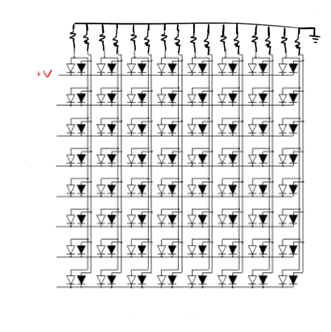
So with the LED’s all reverse-biased, it’s now time to release one of the LEDs from ground and begin reading it.
Here “IN” is the high impedance input of the micro controller. You’ll note the capacitor that I added. This capacitor represents all of the parasitic capacitance on the circuit. It will vary from pin to pin, but with all the wire and the copper rows in the breadboard, you can anticipate it being around a few picofarads.
As current continues to pass through this LED, the voltage across that capacitor will rise. Timing how long it takes will tell you how much light is hitting the LED.
If you were really clever, you could actually read the entire top row at once (well, all the green LEDs anyway). This might prove difficult though, because this whole process can happen fairly quickly (only a few picofarads, remember?), and the code necessary to keep time and record results takes some time to complete. You might run into an issue where a second capacitor charges up while you are still recording the results from the first one. This will cause some data loss and present some issues. To avoid this, I just scanned one pixel at a time repeating this process between scans.
All of the other LEDs can be scanned using a similar process simply by reassigning the micro controller pins appropriately.
Optimization
The biggest issue I ran across was time. This process needs to take place very quickly so that it can change back to display mode without the user noticing. Some of these pixels can take entire seconds to charge up depending on how much light is in the room. To save time, I implemented a time-out where the code gives up if the capacitor isn’t charged all the way after a set amount of time has elapsed. Basically, the sensor doesn’t care how dark the pixel is as long as it’s darker than a laser-illuminated pixel should be.
To make it even faster, I opted to only scan one row each time before switching back to display mode. This reduced the amount of display flicker at the cost of reducing the scan rate. With this in place, the display is less responsive to fast-moving doodles.
Calibration
Remember how I said that the parasitic capacitance varies from pin to pin? This presents a problem as this along with some variation from LED to LED means that some pins might charge up much more rapidly than others with the same amount of light. To address this problem, I created a simple calibration routine that runs when the device is first turned on.
This routine simply measures the charge time of each pixel under ambient light and stores it in a table. If a pixel charges a little faster than the value recorded in the table, that pixel is considered “on”. Basically, each pixel gets its own threshold value.
Code
Here’s a sample of my code from the scan routine. This routine scans a single row at a time (“column” is a global variable) and is called once after every display refresh:
void scanrow(void)
{
    //Port C:
        //PIN0 = LATCH OE
        //PIN1 = LATCH ENABLE (latch is for red ANODES)
        //PIN2 = PORTB.6
        //PIN3 = Reset display
        //PIN4 = Draw in red
    //Port B: Green Anodes
    //Port D: Cathodes

    uint16_t time;
    uint8_t row=0;

    //make the latch output pins all low
    PORTC = PORTC | 1; //turn off latch output enable
    PORTB = 0;
    fixportc(); //a small routine to address
                //the Port B Pin 6 problem.
    PORTC = PORTC | 2; //Set the latch and enable outputs.
    PORTC = PORTC & ~2;

    //advance to new column since last time this routine was called
    if (column<8)
    {
        column++;
    }
    else
    {
        column=0;
    }

    for (row=0;row<8;row++)
    {
        time=maxtime; //maxtime is a global variable
                      //that sets the pixel scanning timeout

        PORTB = 0X00; //bring all red anodes to ground

        //set up row
        PORTB = (1<<row);
        DDRB = (1<<row); //all other rows are set as
        fixportc();      //high impedance inputs

        //set up column;
        DDRD = 0XFF; //all columns are driven low
        PORTD = 0;

        _delay_ms(2); //small delay to ensure that everything
                      //has settled before beginning measurement.

        //this calculation is done ahead of time to save time
        //during the timing loop
        uint8_t temp = (1<<column);

        //release column and start timing
        DDRD = 0;

        //wait until the pin goes high or the timer runs to zero
        while (!(PIND&temp)&&time)
        {
            time--; //decrements are faster than increments
        }
        //compare time to time recorded in threshold table.
        if (time>thresholdtable[row][column])
        {
            //set pixels in the framebuffer depending on
            //state of red drawing button
            if ((PINC&0b10000))
                framebuffergreen[row] = \
                   framebuffergreen[row]|(1<<column);
            else
                framebufferred[row] = \
                   framebufferred[row]|(1<<column);
        }

    //set everything back to normal
    DDRD = 0XFF;
    DDRB = 0XFF;
    fixportc();
    }
}
Here are some notes on the code segment:
- The 2ms delay as it turns out is absolutely vital. Before my lasers arrived in the mail, I was testing this circuit using a flashlight. Using the flashlight didn’t require this delay. My guess is that with such a powerful laser pointer dot, quite a bit of charge will fill up the parasitic capacitors and this charge might then flow into neighboring cells. Before adding this delay, sometimes an entire row lit up at once. This is a similar effect to CCD blooming. The delay allows everything to settle into a predictable state before beginning measurement.
- The calibration routine looks almost exactly like this except it takes the timer results, adds 1, and stores them in a table. This means that the threshold is always 1 unit shorter than the ambient light time (for a noisy environment, adding a number larger than 1 might be appropriate). For some of the pixels, charge time is so slow that basically any time the timer doesn’t run out entirely should be considered an “on” condition. The calibration routine accounts for that.
- The timing loop was optimized to make it as quick as possible. The faster that loop iterates, the finer your timing resolution.
Besides this routine, the rest of the code basically just sets up a timer interrupt. Each time this interrupt is called, it displays a different row of the image. When all rows have been displayed, it scans a row using the above routine and then repeats the process.
Demonstration
Here you can see my display in action:
Conclusion
So the display isn’t the greatest. I had to play with my camera to produce the above video. Looking at it normally, you can visually see it flicker. The LEDs are also not very bright. In addition, you have to draw on it very slowly for it not to miss pixels. The last section of the video was sped up to save your boredom. If you were to draw on it that quickly normally, it would miss most of the pixels.
Despite these issues, I think it works phenomenally well as a proof of concept. I don’t plan on pursuing it any further, but if someone were to take up the reins and optimize/improve the code, I suspect a very fast response time and bright display could be made in a similar fashion.



Good work
Now go make a game out of it. “Catch the dot”, “Simon says” or maybe even some sort of a maze game.
Pingback: Writing on LEDs with a laser pointer - Hack a Day
You should investigate moving to a different ATMega chip. I’d bet you could quadruple your clock speed (quartering your loop time) with little effort.
Also, your captcha is set too aggresively. I spent like 2-3 minutes trying to enter it correctly.
Actually, most of the loop time is spent waiting for the LEDs to settle, a faster chip wouldn’t really help. To make it faster, you’d need some better LEDs or a better algorithm.
Sorry about the captcha. I actually had a weaker one earlier, but I kept getting spam comments about discount watches (what is it about watches?).
Pingback: The ch00ftech Guide to Breadboarding | ch00ftech Industries
You could optimize by memorizing the pointer’s position, and start by reading from the adjacent cells towards the more remote cells. As soon as you find the pointer, you stop the loop and start displaying.
Not a bad idea! My only concern with that solution is that the visible flickering would change speed depending on where the laser was. Might not be that noticeable though!
Pingback: The Laser Doodler « adafruit industries blog
Pingback: Writing on LEDs with a laser pointer « debuti's Blog
Very nice! I was working on something similar (http://youtu.be/a1ueQ7cmRw4) but never got around to coding the sensing. I was planning to connect an NPN-PNP half-bridge to each common cathode, so that I could pull the cathode low to light the LED, and high to sense. Each anode had its own I/O pin, so it required 24 I/O total, but you could connect the common cathodes to a shift register or a 3:8 decoder to reduce that.
Wow! That’s an awesome gadget! Do you have any details on the build?
http://robotguy.net/blog/?cat=26
Pingback: MAKE | Laser Doodler Draws on a LED Matrix
Pingback: Laser Doodler Draws on a LED Matrix
Maybe you could use the green as the sensor and red for display only? This way you wouldn’t have to clock at all since you don’t have to reverse the LEDs. Obviously you don’t get multicolor, but hey, it shouldn’t flicker.
Unfortunatly, the way the LEDs are wired in the display, this is impossible. Turning on the green LEDs would interfere with reading the red.
Pingback: Laser Doodler lets you draw on LEDs with a laser pointer | Stock Market News - Business & Tech News
Pingback: QR Clock | ch00ftech Industries
Pingback: Write on LEDs using a Laser! | Arkane Interactive