Whaaat? You can do that?! You need phototransistors or photodiodes silly! Turns out, you don’t. IT’S A CONSPIRACY!
Seriously though, LEDs can be used as photo detectors. It’s not as simple as using a proper photodiode, but it’s a pretty neat trick and can save you a few parts if you’re working on a budget.
First, let’s discuss what an LED is.
Light-Emitting Diode
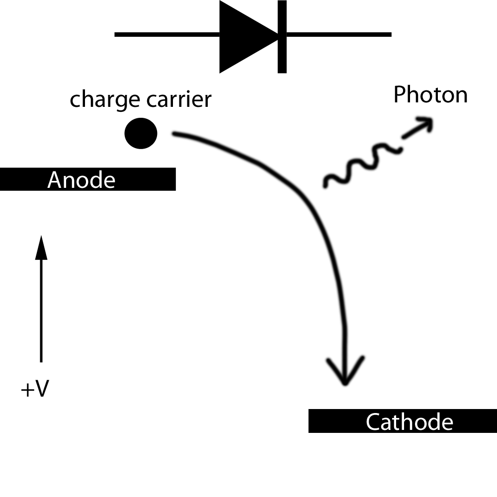
LEDs contain a small junction of specially doped silicon. The details are a little complicated, but all you really need to know is that this junction sets up a “band gap”. Visually, I like to think of a band gap as a large stair step where the vertical axis represents voltage:
 If you are able to raise the anode step up high enough (the forward voltage of the LED), you can get electrons to fall down to the cathode. As they fall from this high energy state to a lower energy state, they release a photon of energy equivalent to the energy lost during their fall.
This explains two cool facts about LEDs:
- With light, low frequency colors (red, yellow, etc) have less energy per photon. This is why blue and green LEDs have a higher forward voltage. The electrons have to fall farther to release more energy and get higher-energy photons.
- This is why LEDs need in-series resistors. Once you’ve got your electrons up to a sufficiently high energy state, there’s nothing to keep the lot of them from pouring down that step and potentially blowing out the LED.
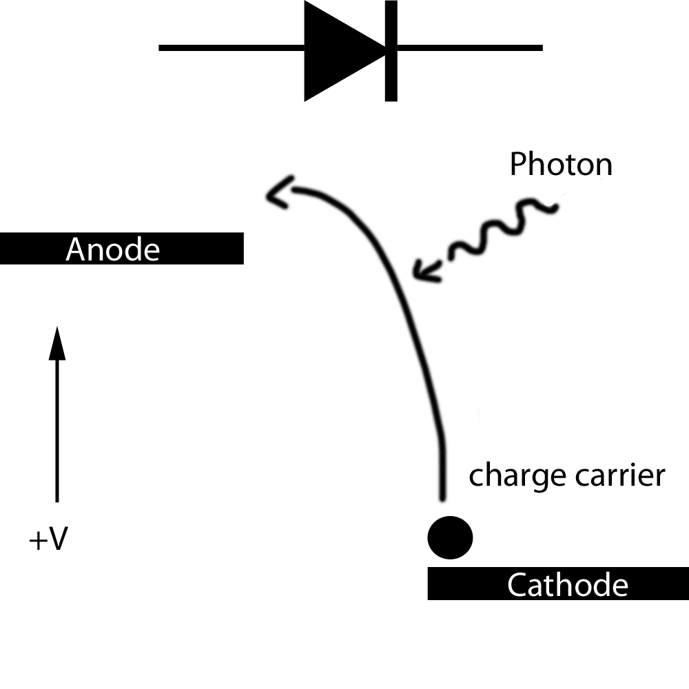
Now. Here’s where a cool trick comes into play. If you reverse the paths of the charge carrier and photon in that image above, it still holds true.

This is what Einstein calls the “photo-electric effect”. Assuming the incoming photons are of high enough energy to raise the electrons on the cathode up to the anode, the junction will produce a current (if the photons aren’t energetic enough, the charge carriers will just fall back down to the cathode and produce heat).
If you look at a solar panel, it’s really just a giant junction that will produce current when exposed to light. This is also why most semiconductor products are housed in black plastic. Incoming light could potentially produce small currents that could disrupt performance.
Now, it’s worth keeping in mind that this effect is exhibited more in some devices than others. It will vary depending on how the junction was doped. In the case of LEDs, this photo-current is extremely small. On the order of maybe a micro-amp or two. Currents like this are extremely difficult to measure, especially considering that the idea here was to reduce the number of components.
Capacitors turn Current into Time
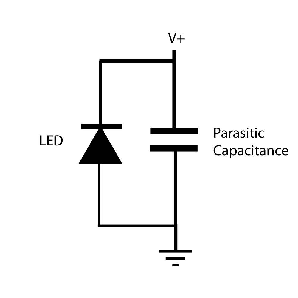
To measure this current, you just have to take advantage of parasitic capacitance. Every single component on any PCB exhibits some kind of capacitance. In some cases, such as in high-speed data lines, this capacitance can be an issue. For this project though, it’s welcomed.
To perform this trick, I started by connecting an LED across two pins of my micro-controller. I know you’re always supposed to have a current-limiting resistor in series, but I figured that I’d leave it out for simplicity’s sake. The output impedance of the micro-controller isn’t exactly super low anyway.
The IO pins of the ATMega48 I was using can be configured as either outputs, high-impedance inputs, or high-impedance inputs with a weak pull-up resistor.
The basic idea is to build up a small amount of charge on this parasitic capacitance and then let it slowly bleed through the LED. The more light hits the LED, the more current the LED generates, and the faster this charge bleeds off. While current is hard to measure, time is extremely easy to measure. All you have to do is time how long it takes for the voltage on the cathode of the LED to drop.
I started this process with the IO pins in the following configuration:

In this configuration, the capacitor charges pretty much instantly. Next, I changed it to high-impedance input with a pull up resistor. Electrically, this step doesn’t do much new, but it does prepare the micro-controller to “let go” of the cathode. I figured it was better to charge the capacitor with the pins in output mode, rather than through the pull-up.
Finally, I dropped the pull-up, letting the cathode float, and immediately started a timer to see how long it would take the LED to dissipate the charge. You don’t even need an ADC for this step. As soon as the voltage drops below the V-input low, the micro-controller will read a low voltage, and you can tell it to stop timing.
All of this is accomplished in the following code snippet (sorry about the formatting, I’ve been battling with wordpress lately…)
uint8_t count(void)
{
    uint16_t time = 0;
    PORTB = (1<<cathode); //force cathode high and anode low
                          //to charge the "capacitor"
    DDRB = (1<<anode);    //turn the cathode into an input
                          //still held high by internal pull-ups
    PORTB =0; //release the cathode.
    while (PINB & (1<<cathode))               //time how long until the voltage
        time++;                               //cathode drops below V_input_low.
    DDRB =  ((1<<anode)|(1<<cathode));        //turn anode and cathode back into
                                              //outputs so the LED can be used.
return time;
}
Benefits
The coolest part of this technique is that when you’re not actually measuring the ambient light the LED can be used as…well… and LED! It’s just a matter of reversing the pins and driving the LED normally. For long-term use though, you might want to consider integrating a series resistor. Given how low the currents are, a 100ohm or so resistance probably wouldn’t make any difference.
Drawbacks
There are quite a few drawbacks. Some of the simple ones include the fact that an LED will only detect light that is a higher frequency than the light it emits. If you have a blue LED, you will be unable to detect red light.
The LED can’t be lit while it’s in detection mode. This isn’t too much of a problem until you start getting into dark situations. Sometimes, if it’s dark enough, it can take a number of seconds for the cathode voltage to drop. You might be able to fix this problem by putting a huuuuge resistor in parallel with the LED, but the highest I had was 470k, and that wasn’t big enough.
When I first ran the code snippet above, I noticed that my time measurements seemed to get a lot noisier as light-level decreased. Commenter Josip pointed out that I wasn’t using a large enough variable to store the time, and it was overflowing, causing me to take “random” measurements. Running it again, I found that even a uint32 isn’t large enough to prevent overflow, so if you use this code, you’ll have to find some way to accommodate small and very very large numbers.
Finally, no two LEDs are the same, and the measured values can change dramatically because of things like ambient temperature and humidity as well as circuit board layout (anything that can affect capacitance). For my little demo, I just found a value that looked good and used it as a threshold. In reality, you would need some kind of calibration routine.
Conclusion
The below video is a short demo of this application. The code takes a measurement of the ambient light entering the LED then decides whether it’s going to keep the LED on or turn it off. It then takes another measurement after a short delay, and the process continues. The idea is for it to act like a night light, only turning on when the room gets dark. As you can see, this plan backfires when the room gets too dark as it spends so much time waiting for the LED’s capacitance to discharge that it becomes noticeable and then downright useless. In a real application, you would have to find some way to accommodate this delay perhaps by only taking a measurement every 30 seconds or so.
Overall, it was a pretty cool project. I have a plan to make a sort of simplified image scanner that will be made much easier using this method.

Very interesting project! I’ll be sure to try it. About the sporadic timing at lower light levels; if you used the actual code you provided, I’d say that the problem is in time variable which easily overflows if set to uint8_t. At lower lights it takes longer to reach threshold and 255 counter would last only about 100 us at 8 Mhz clock.
Good point! I actually messed the code snipped up when cleaning it up for the site. I actually used a uint16_t which should be long enough for up to 25ms delays, but that still wouldn’t be enough as some of the delays can be seconds long.
Just for kicks, I commented out the section of my code that compared the results to threshold and just had it turn on the light whenever it wasn’t doing a reading.
What I noticed was a slow, but steady blinking of the light. Nothing as random as what I was reading last night. Thanks for commenting!
Another cool project based on this idea: http://mrl.nyu.edu/~jhan/ledtouch/index.html
Nice hack. can you put the schematic also
Check out the video. The schematic has two components….should be pretty easy to figure out.
About the long measuring time in dark. Just add a time out at the threshold value:
If measuring time is longer than x ms then light on. (Don’t wait for actual value)
If less then recharge capacitor and repeat whit light off.
Funny that you say that. I actually did exactly that in the “Poor Man’s Cap Sense” of my digital menorah.
Assuming I understood it right…
Could you add a timeout in the while loop? If it takes longer than x loops, then break out and assume its dark?
Note to self, dont hold comments in draft stage for too long…
Pingback: The Laser Doodler | ch00ftech Industries
Hey,
I mostly code for ARM and PIC so I am not sure if arduino has the capabilities (I assume it does). Have you thought about using an on chip timer for the discharge time tracking? You could have it be self resetting, and just add a code snippet for when the timer overflows to increment a variable. In the approach you would have a course grain resolution (timer overflow count) and fine grain (actual timer value) resolution of the time to discharge. In addition, your timeout as mentioned by two previous posters could be as simple has when the (insert number here) overflow occurs, then it times out.
ps most timer modules have a configurable prescaler value that divides the uC’s primary clock rate to give you a larger timebase.
good luck!
Hi there,
Firstly *please* don’t call it an Arduino. I use raw AVRs without the Arduino for a reason.
Secondly, you’re absolutely right about the timers. I actually used a very similar technique in my 60Hz timing code (https://ch00ftech.com/2012/07/24/are-you-sure-about-that-60hz/) where precision was absolutely vital.
This application is sort of just a quick hack for demonstration purposes though, so I went the lazy route. Your solution is definitely more robust.
Hi i am only begining with C programming and blinking an LED is a challenge could you please provide me with the full code so i can see how it all works ?
Hello,
I always try to avoid giving out all of my code and process information because I believe that the best way to learn is to try to solve problems yourself. That being said, if blinking an LED is a struggle, you might want to try on simpler projects first.
If you’re just now starting on blinking LEDs, why don’t you blink a whole bunch of LEDs and make a persistence of vision display like this one?
https://ch00ftech.com/2011/10/24/led-persistence-of-vision-toy/
It doesn’t have to be a LED, any diode with a clear body (like 1N914) will work as a photo detector – the current out is proportional to the light intensity.
Right you are though an LED offers better lensing that help increase the sensitivity.
You also get the light-emitting aspect which is pretty cool.
Definitely, I just wanted to point out that there is nothing intrinsically special about a LED PN junction over any other exposed PN junction.