If you’re a resident of Seattle, I highly recommend you check out the Bubble events group. One of their regular events over the summer is something called “Nocturnal Push” where you can get decked out in your best glow gear and cruise the Alki Beach strip on your bike, longboard, or whatever.
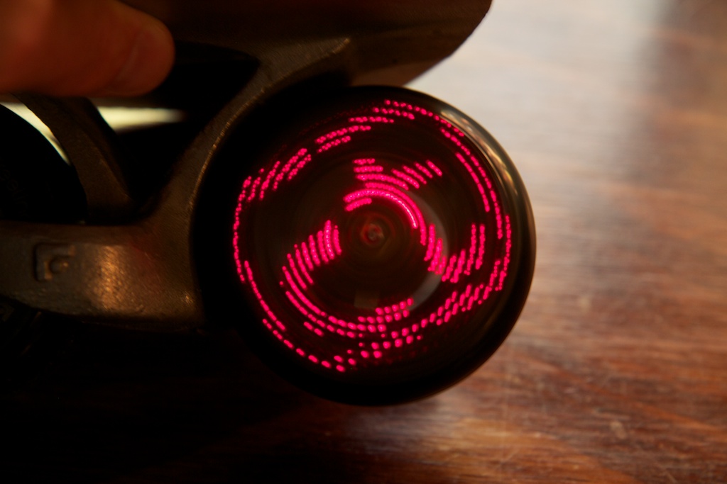
That’s why I made this:
 Background
So I’m no stranger to persistance of vision LED displays. One of the first projects posted to my blog was my POV toy about this time last year. I also made the “Ice Breaker” which operates on the same principle. Persistence of vision is a very simple concept. By moving an array of LEDs quickly and blinking them in a specific pattern, you can utilize the slow response of your retinae to produce what appears to be a stationary image.
In fact, one of the first micro controller projects I ever attempted was a persistence of vision display system for a bike wheel back in 2009. I had just finished my first class on embedded design and I saw a video of Monkey Electric’s wheel lights. Knowing nothing about AVRs, I decided to attempt to make what they made using a raw 8051 with an external ROM and RAM chip all in assembly because that’s what we used in the class and I didn’t know any better.
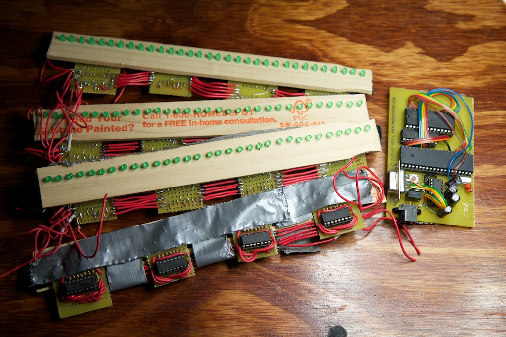
Working with my friend Collin, we produced this:
We code named it “Green Moon” and didn’t make it much farther than what you see here. Those are paint stirrers if you’re curious.
But I digress.
Objective
So I’ve done persistence of vision displays before; there’s really nothing new there. The challenge this time was to make it small enough to fit on a 72mm longboard wheel, and to make it cheap enough so that I could mass produce it and sell it to folks in the area.
So boiling it down: I needed a consumer-ready stick of LEDs that I could control with a micro controller with a sensor that can detect wheel speed all for as cheap as possible.
Unfortunately, I didn’t quite accomplish all of these goals, and since I haven’t touched this project for over a month, I decided to officially put it to rest for the time being. I didn’t want to deprive you guys of a blog post though, so read on to find out how it works and see if you can improve it!
Schematic
LEDs
One of the benefits of doing a display on a longboard as opposed to a bike is that during regular use, a longboard wheel rotates many more times per second than a bike wheel. This means that it’s much easier to attain a high enough refresh rate to achieve persistence of vision. Instead of using the four arrays of LEDs like in the MonkeyElectric display which effectively refresh the image four times per rotation, I would only need one array of LEDs to refresh it once per rotation.
I wanted my display resolution to be much higher than the 8 pixel display of the Ice Breaker, but my micro controller of choice (the ATTiny24) didn’t have enough pins to spare, so I couldn’t do the one to one LED mapping that I had used before.
This means that I had to multiplex the LEDs. This presents a problem with a persistence of vision display though because when you think about it, the display itself is already “multiplexing”. It’s core function involves it only showing a single row of light at a time.
With the array multiplexed, each single row of the image involves flashing light from multiple banks of LEDs quickly in sequence. I was worried for a while that my micro controller wouldn’t be fast enough to flash all three banks of LEDs in sequence before moving on to the next row of the image. There’s also the problem of image distortion resulting from the array moving too far while a single bank is turned on.
This turned out to not be a problem as the micro controller was plenty fast. I shouldn’t have been surprised because this is exactly how the POV toy I took apart worked.
In the interest of keeping costs down, I picked the cheapest LED I could find. Pricier, more efficient LEDs would create a brighter display, but I figured that it was a sacrifice worth making as this thing was only meant to be used at night.
Sensor
The other main component of my circuit was a sensor to determine the wheel speed. In order to display a steady image on the wheel, the micro controller would need to know approximately how fast the wheel was turning so it could blink the LEDs at the right times.
There are a number of ways to gather this kind of data such as electrical contacts and optical sensors. I’ve even seen a rotating POV display that uses a electronic compass to determine the rate of rotation based on the changing direction of magnetic north. I thought at first that I could use an accelerometer to detect that change in the direction of gravity, but I reasoned that the regular vibrations associated with riding a longboard on pavement would far overpower the acceleration due to gravity making an accelerometer useless.
I settled on using a 90
![]()
IR reflection sensor:
This sensor consists of an IR LED and an IR phototransistor. When the light from the LED reflects off a surface (in this case the ground) and into the phototransistor, the transistor turns on passing a signal to the micro controller which triggers an interrupt. Once per rotation, this sensor would be pointing down towards the ground and not only give the wheel speed information to the micro controller, but also orientation information for images that must be displayed upright.
After a few tries with this design, I had to give up on it. The amount of light reflected off the ground varies heavily depending on what kind of surface you happen to be rolling over. IR acts similar to visible light in many ways, so a white concrete sidewalk will reflect much more light than black pavement. I found that no amount of fiddling with the power output of the IR LED or the sensitivity of the phototransistor could make this design work consistently on any dark surfaces.
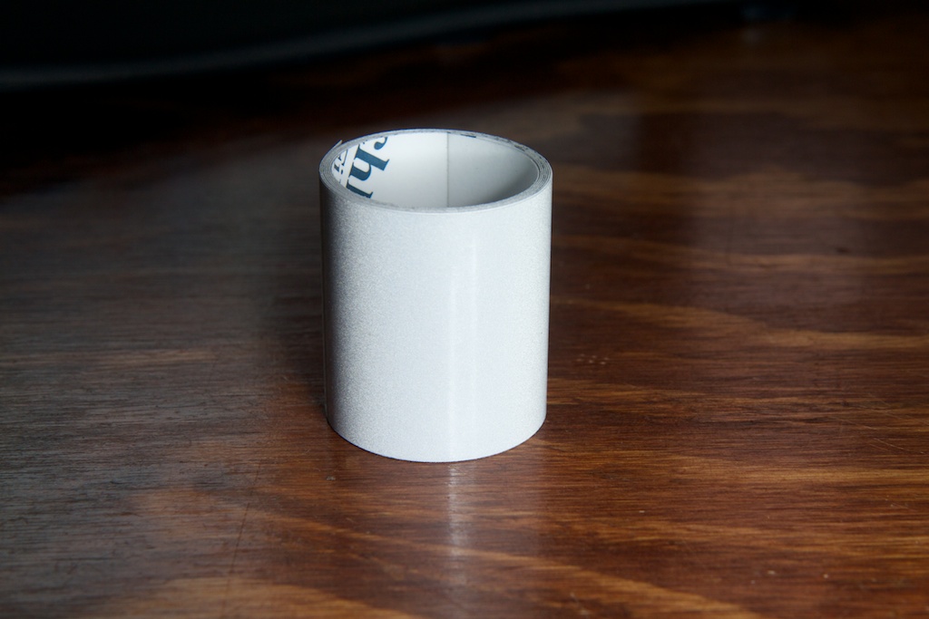
I then had the idea of using the longboard deck itself as the reflective surface. This would offer a surface at a constant distance with a controlled level of reflectivity. Unfortunately, on the longboard my friend lent me, the wheels were too far from the body of the board and there wasn’t enough IR reflecting back. I even tried adding some retro-reflective safety tape:
Which despite being really cool stuff, didn’t help too much. Even if I had gotten it to work, it depended too much on longboard geometry which isn’t very consistent between decks (some longboards have wheels that extend past the edge of the deck), so it would be less viable as a commercial product.
My next design placed the reflector inside the wheel. Longboard wheels are designed with the bearings built into the body of the wheel. This means that the wheel’s axle doesn’t rotate at all. By affixing a reflector to the axle I would have a steady measurement point that my circuit would pass once per cycle.
The reflector itself was hard to come by. My prototype used a piece of cardboard cut to shape and glued to the axle nut:
Presumably, a commercial version would come with a piece of shaped plastic that could be threaded to screw into the end of the axle bolt or shaped to fit around the nut. This was mildly off-putting as there would be costs associated with getting plastic custom formed, but it started to look like the only option that would work.
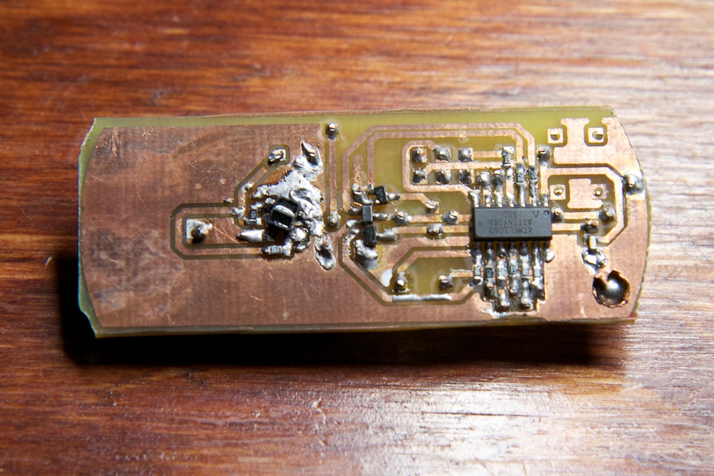
Opposing this reflector was another IR reflection sensor except this one was a surface mount model placed on the bottom of the board:
I messed up the footprint a little when printing the PCB, so it was a little ugly soldering it in…
With some minor tweaking of the IR LED and sensor, I found this method to be nearly flawless. What’s even cooler is that the orientation of the image displayed can be altered by moving the reflector around.
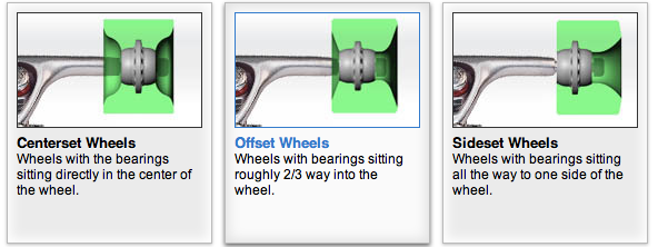
The main problem with this design is that again, it depends too much on board geometry. I thought going into this project that all longboard wheels are the same. I found out later that they vary quite a bit as this graphic from MuirSkate.com demonstrates:
I was thinking at first that I might be able to accommodate different wheels using different reflector shapes, but even among these categories, the wheels vary a bit, so anything designed for a specific offset wheel might not fit on another offset wheel. Furthermore, I don’t even know that I’d be able to get sideset wheels to work at all.
This is the problem that eventually killed this project, however the current design does work perfectly fine with my Freeline skates which have wheels that very closely resemble 72mm centerset longboard wheels in size and shape. While it’s a working design, it’s not a commercially viable one.
User Input
The device has one button. Deal with it.
PCB design
My major concern when I started designing the PCB was keeping the device balanced. I was worried that any minor weight imbalance would cause the wheel to vibrate annoying the rider at best and tearing the PCB from the wheel at worst.
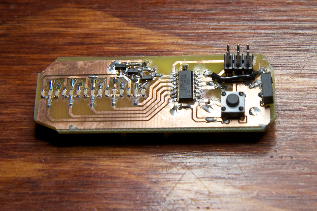
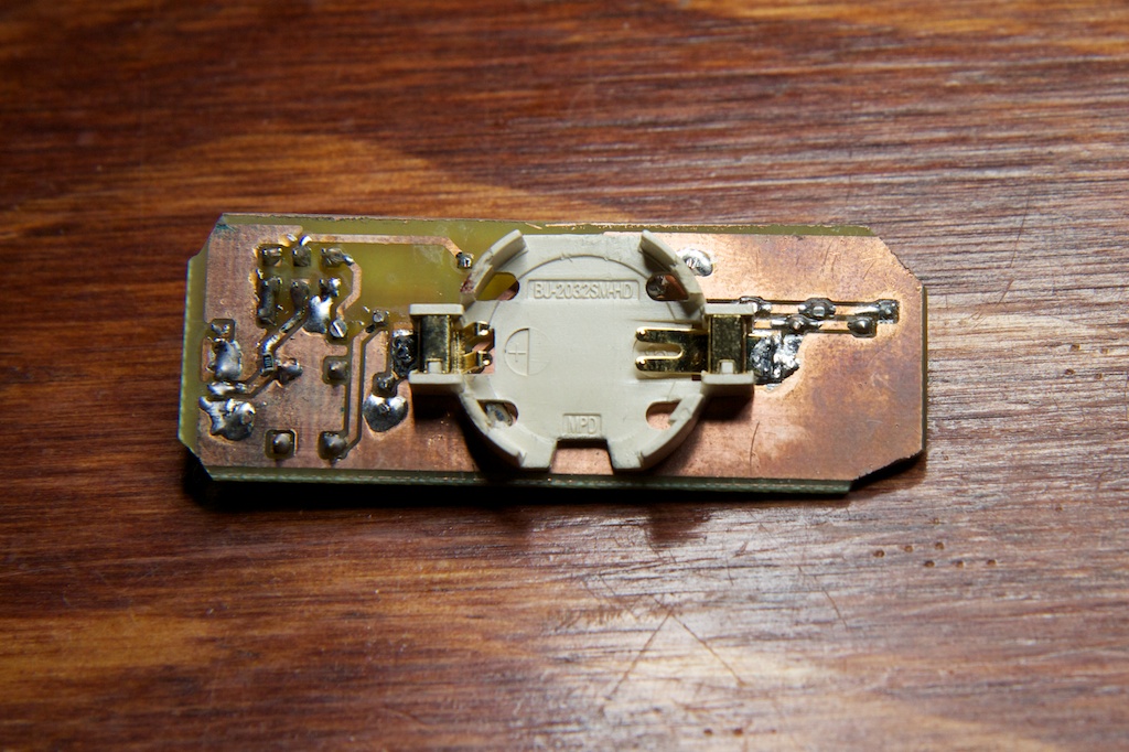
Because of this, I placed the battery (the heaviest component) directly in the center of the board:
The battery was too large to place on the top of the board as it would get in the way of the LEDs, so I had to place it on the back. This ended up being a problem for a number of reasons. The battery protruded so far from the PCB that it would hit the axle before the board could lie flush against the wheel (which might not have been a problem with a sideset wheel).
Also, at the time I was thinking that the board would need to be mounted relatively permanently either with small screws into the wheel or with some kind of semi-permanent adhesive. Putting the battery on the back would make it impossible to replace without removing the PCB.
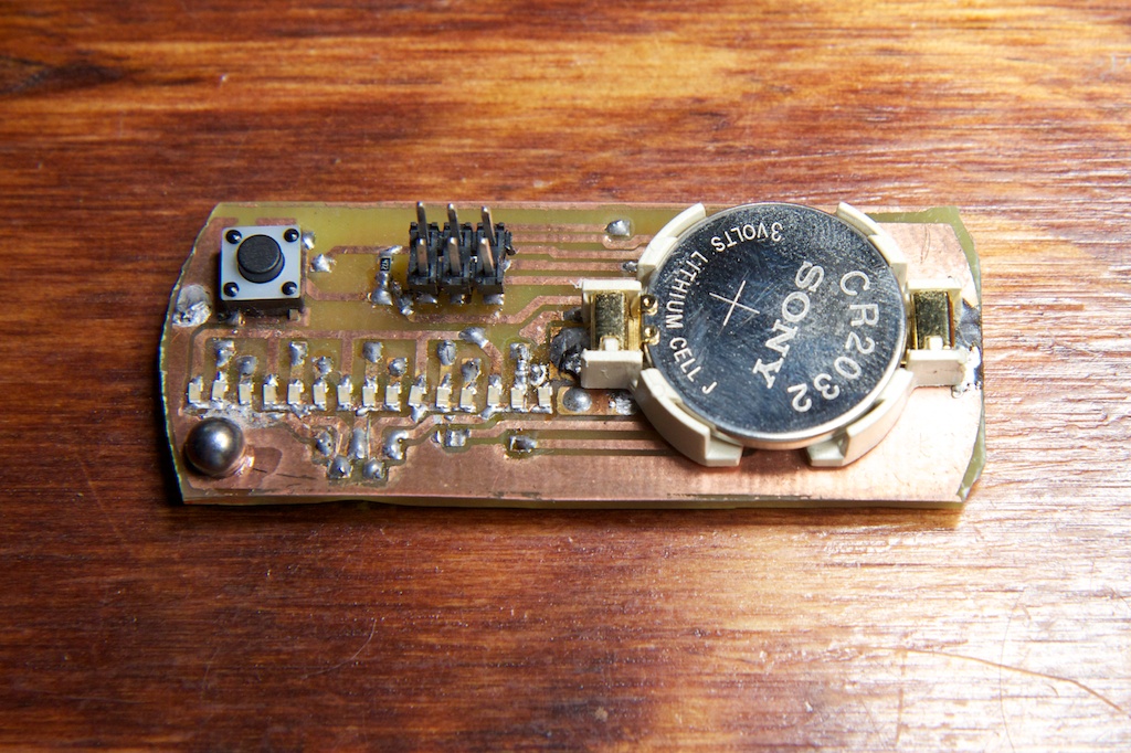
I opted instead to put the battery on the top:
This unfortunately required me to move the row of LEDs slightly off center, but it turned out to have a negligible impact on the displayed image.
This set the wheel completely off balance, so I looked around online for some type of cheap counterweight. I remembered buying lead weights for my pinewood derby car when I was a kid, so I looked for those. Apparently kids these day aren’t badass enough to deal with the dangers of lead poisoning, so they moved down to tungsten. Tungsten is another dense metal, and tungsten spheres marketed for pinewood derby racers can be obtained very cheaply off Amazon:
They have a diameter of 4.5mm and weigh in somewhere near 1g (my scale is only so precise though Wolfram Alpha places it pretty close to that). The battery itself only weighs 3g, so a clever placement of a tungsten sphere near the edge of the board should be able to balance it.
I drilled a hole near the opposing edge and glued one of the spheres into it. I didn’t get the balance perfect, but it’s pretty close. I think it could be made perfect with minor adjustments.
Power Management
The one new aspect of this project is how it’s turned on. Shopping around for power switches, I found a lot of them to be really expensive. It’s actually pretty hard to find even a crappy slide switch that’s under 50 cents. To reduce the cost of the power switch, I opted to not have one all together.
Instead, my device simply goes to sleep. In sleep mode, the ATTiny24 draws just 2uA which means that it can stay like that with a CR2032 battery for about 13.6 years before the battery dies. This might as well be the same thing as turning it off entirely.
I designed the firmware with a timer that is reset every time the button is pressed or the IR sensor picks up the reflector. When this timer runs down to zero (about two minutes), the micro controller turns off the LED array and IR sensor and goes to sleep. It can only be woken up by pushing the button again.
Unfortunately, despite all of this, the battery life of the unit isn’t very good when it’s awake. Because of the shape of my reflector and the distance to it from my board (which is separated from the wheel by a thick piece of foam tape), the IR LED still has to be fairly bright. This means that when the unit is idling (not displaying an image), it’s drawing 13mA of current.
This number could be greatly reduced by changing the shape of the reflector to reduce the distance from the sensor (something I would do if the reflector was precisely molded from plastic).
It could also be potentially reduced by polling the IR sensor once every millisecond or so instead of leaving it on continuously. This could cause a problem though because the firmware wouldn’t know the precise moment the reflector came into range, it would only know the first time it was polled. This lack of precision could cause the image to flutter similar to how it did in Icebreaker 1.0. Care would have to be taken to make sure the polling rate was fast enough
Pattern Generation
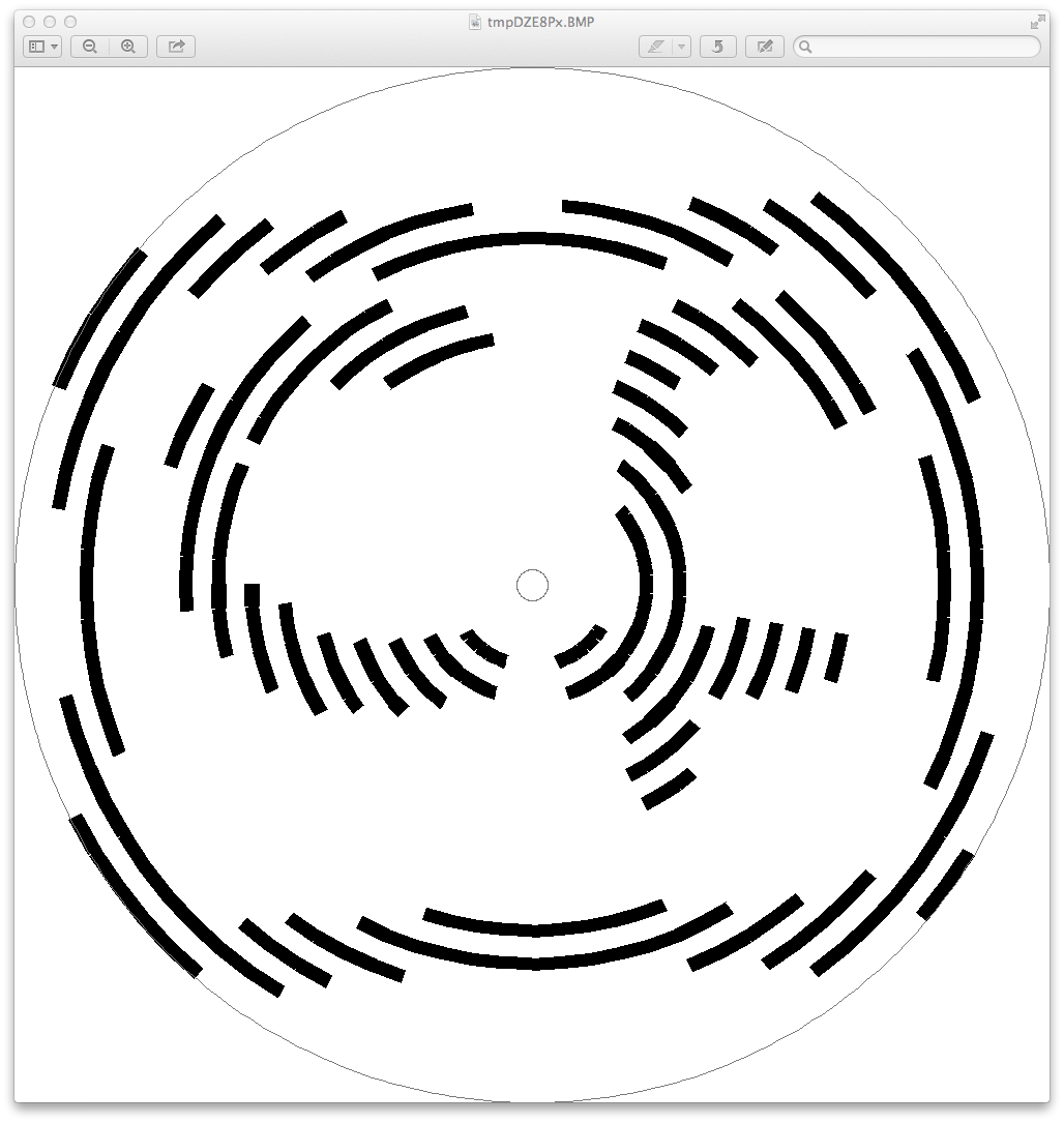
The patterns are all generated using a python script on my computer. This script takes in a 2 color PNG file and outputs an array of LED values along with an image simulating what the result will look like:
I found out after the fact that when mounted on the right wheel of my front skate and rolling forward, the image is mirrored. Also, the placement of the reflector causes the image to be rotated 180 degrees. To counter this, I flipped and rotated my PNG before sending it to the Python script so it would come out right.
A commercially viable device would need to have a method in the firmware for displaying the images in reverse in case the device was mounted on a left wheel and thus spun “backwards”. Perhaps the mode could be changed by holding down the interface button. I didn’t bother including this feature in my prototype.
I found that my device could hold just 4 patterns. Each pattern was made of a 160 element array of 1-byte values (each radial row of image was 15 bits
![]()
2 bytes). With the overhead from the compiler, that worked out to about 188 bytes of micro controller program memory per pattern. While my ATTiny24 only had enough room for 4 patterns in addition to the core firmware, its 8k counterpart could use its additional 6,000 bytes for patterns and store an estimated 35 total.
It would be nice to allow the end user to design the patterns, but the human interface parts required to pull that off would increase the cost of the unit substantially. I put this device in the same category as the blinky light things they sell at the circus. It’s kind of neat, and it’s really cheap.
Pattern Reproduction
The firmware for displaying these patterns is incredibly similar to the firmware of the Ice Breaker. Simply put, there’s a timer that measures how long a single rotation takes and then a function splits that time up into 80 equal increments. Every time 1/80th of the cycle elapses, the firmware displays the next row of the image. Assuming the speed of the wheel doesn’t vary too much between each cycle, this method should produce a fairly stable image.
When the wheel has stopped rotating for a second or so, the firmware stops trying to display the image and instead illuminates a single LED that represents which image it’s currently trying to display. This makes it easy for the user to select their desired image without having to spin the wheel to find out which one they’ve selected. The image is changed by pushing the button.
Demonstration
I took the display for a spin outside and tried to get some footage of it working. POV displays never play nice with cameras, so if you can imagine, it looks a lot better in person.
Conclusion
So again, I didn’t quite achieve what I set out to do, but it’s still a pretty neat gadget, and I really like how I got the power management to work. The simplicity of a single on button and an auto-shutoff is a really nice feature that I’d like to work into some future designs.
It was also a lot of fun designing a product where one of the ultimate goals was absolute cheapness. I was much more willing to take risks that potentially sacrificed the quality of the device and explore some new techniques (such as multiplexing) that I usually try to avoid.
The per unit BOM cost for components from Digikey purchased in the quantities required to make 50 units came out to ![]() .22 if I got them from Amazon. Considering the PCB is only 2.5 square inches, I imagine the PCB and assembly wouldn’t be much more than a few dollars if purchased in large enough quantities. All together, I think this kind of device could retail for a price somewhere around $6-10. Perhaps a set of four would get a discount.
.22 if I got them from Amazon. Considering the PCB is only 2.5 square inches, I imagine the PCB and assembly wouldn’t be much more than a few dollars if purchased in large enough quantities. All together, I think this kind of device could retail for a price somewhere around $6-10. Perhaps a set of four would get a discount.
I might pick up the idea of a wheel-mounted persistence of vision toy at some point in the future. I had an idea for combining the image scanning capabilities of the POV toy I reverse engineered with something wheel-mounted that might make for a fun project.
Project files can be found here: Longboard Wheel DIsplay v1.1






I’ve fiddled around with tracking PORF versus EXTRF on the ATtiny chips for waking up from sleep. The gist of my design is that it uses a reset switch to wake up, runs the display until the timeout condition is met (4 hours-ish), then falls asleep. If I hit the reset switch while the chip is awake, it increments the display mode, otherwise it just wakes up and starts displaying the last display mode. _Occasionally_ I manage to cause it to freak out and it returns to the default mode on wake instead of the last mode, but I haven’t been able to track down where the glitch is occurring.
Battery life has been kind of surprisingly good even on a 2032 and sleep mode seems to just go on forever with my 3xAA projects. The low power sleep is incredible, even if the chip is slightly catatonic.
Source here: https://github.com/pfriedel/TinyFiveCircle/blob/master/TinyFiveCircle.ino (I still need to sit down and put the drawing routine into an interrupt so I can just write changes to the array, and the Larson scanner code is pretty rough. It’s mostly an excuse to make a shiny board.)
Odd bug. Have you tried writing the current display mode to the onboard flash before sleeping?
Ah yeah, and going over it, I think I figured out where it’s happening – I’m writing the last mode to EEPROM and going to sleep without enough of a delay after the write, and I seem to recall that the datasheet warns about that. I’ll dump a delay in there and see it it clears up. It’s been low priority, but I suppose since the boards are coming over on a jet plane as stocking stuffers, I should probably finish off the debugging.
Can you do something with a Hall effect sensor? I don’t know much about how close to the magnet they need to be. Could you mount the magnet on the axel shaft inboard of the bearing, and have a short wire pair that protrudes from the POV device, through the spokes, with a Hall effect sensor that spins with the wheel, taking it past the magnet once per rotation? Of course, that makes mounting this much more difficult for customers.
You know, I never really looked at Hall effect sensors because I assumed that they’d be prohibitively expensive. Looking at Digikey right now, I found some that are actually a good 20 cents cheaper than my IR sensor. Though that’s not taking into account the cost of the magnet.
You’re right about the mounting. It would require a magnet to be attached to the board somehow which might cause the same problems that I saw with the right angle sensor. If only all the roads in the world were magnetized somehow… 🙂
Roads with induction coils in them for power-pickup? 😉
I think attaching the magnet to the axle shaft would be easier than mounting something to the outside end of the shaft. I figure you’d be able to just wrap some tape around the shaft, with the magnet where you want it for the rotation angle of the display. I think the hard part would be getting the hall sensor to “hover” exactly where it’s needed. If a hall sensor can be quite a distance from the magnet, that may not be all that hard. Use a solid wire from the main PCB to the hall sensor, and just bend it until the hall sensor is where you want it. That said, depending on how heavy the hall sensor (and tiny PCB?) is, centrifugal force may be a problem, pulling it away from the magnet.
Well on top of that, the goal was to make it stupidly easy for a non-EE to setup. Any kind of minor adjustments required by the end user will vastly degrade the value of the product.
an accelerometer on the board would, in theory, produce an output exactly proportional to the rotation rate because it would be measuring centripetal force, and then gravity would superimpose a sinusoidal signal on top of that signal because of the orientation of the accelerometer changing.
I actually thought about this problem. You’re right that it should absolutely work in theory, but there are a few practical considerations that make it less than easy:
1) For a precise rotational speed, the exact radius of the accelerometer must be known. If the user installing it doesn’t center the board exactly right, the measurements will be very far off the mark.
2) Even riding over small grains of sand on a skateboard will produce accelerations of the board that are far greater than the acceleration due to gravity. The noise of riding over anything but a perfectly smooth surface will likely drown out the gravity signal.
3) Lastly, the acceleration on a longboard wheel is actually quite high when you consider how fast you move and how small the wheel is. For example, when the board is moving at just 10mph, the outside of the wheel is experiencing 56g of acceleration! Unless you can place your accelerometer near the center, you’re very likely to max out the 3g range of most low-cost accelerometers that are made in mass quantities for the cellphone market. Anything that works outside this range is going to be a specialty accelerometer that will cost a *lot* more.
Great idea though! I was thinking this might be a very elegant solution to a similar device made for a bike tire. Bike tires are softer and don’t vibrate as much. They also rotate a lot slower. And a device made for a bike tire is going to be much more expensive anyway, so your BOM can likely take the price hit.
@Derek regarding idea roads with induction coils:
Most stop lights actually use a gigantic coil underground to detect cars, maybe try harvesting that energy?
Consider this: the rotational velocity at the axle is less that at the outer rim of the wheel. A Hall sensor mounted at the axle would not have as much force on it as one mounted outboard. It should also be more accurate, since the pulses would be easier to read. Or?
I’m not sure what you mean. The amount of centripetal force on a Hall effect sensor is irrelevant. Besides, putting it near the axel means that it will move less every rotation which will make it more difficult for the sensor to accurately detect where it is relative to the magnet.
Pingback: POV wheels for a longboard - Hack a Day
Nice one!
have you thought of using an inductor to determine rotation? there is metal around, so you should get a changing signal out of a coil. together wit some analogue circuitry such as schmitt triggers for signal cleaning i think it could be an option to get rid of the ir led and receiver.
cheers,
jan
Interesting idea, but I still think the signal would vary a lot from board to board, so it would be hard to sell it to a mass market.
Pingback: Belgaum news | About Belgaum | Belgaum information | Belgaum district | Belgaum city | Belgaum Hotels | Belgaum People | Belgaum tourism | Belgaum entertainment | Belgaum students | Inside facebook | Hack | make use of | technical news | | POV wheels for
Could you get the LEDs centered if you rotate the battery holder a bit?
That would increase the board surface area which would increase the cost slightly. As is, you really can’t tell that the LEDs are off center when you spin it as the angle is very slight.
Cool hack man, what type of longboard is that? I have never seen one with wheels set up like that and have a few 4 footers myself.
It’s actually a pair of Freeline skates. I don’t own a longboard, but the skates use the same size wheels and the same type of bearings, so this design will work on a longboard.
also what about casting your own wheels and deadbug style the electronics or flex board inside the wheel then offset balance internally. the leds would be a part of the wheel as well. even the batteries could be put inside with a small solar strip to keep em topped off. that what you don’t have the dust and particulate to worry about…
Well, of course that would work, but the goal here was to create a cheap accessory that could be retrofit onto normal wheels.
I think it is very clear and well done. good job!!!
I did some speed-controlled lights for my longboard and used a hall sensor sugru’d to the axle and two 3/16″ neodymium magnets pushed into holes drilled in the wheels. It works great. Yours could be the reverse: Hall sensor (I salvaged mine from a PC case fan) on the end of your PCB and then a strong neodymium magnet attached to the board itself. I know that was mentioned before, but I wanted to say that I had my own success doing it in reverse at least. Great project!
OK. Keep using the reflective sensor. But split it into two. The gap in between will give you an extra pulse. This will tell you rotation direction…
Mount the reflective tab on the nut with a nut shaped cutout (rectangle). Deal with the different heights of the wheel styles by having the sensor come up vertically off the nut. I.e not mounted side on but sticking out in same direction as axle.
The user cuts the tab down until its the right length for their wheel.
The reflective tab could be a simple lasercut shape (used end on). Rectangle at one end (to fit nut) offset slot at other end. Produce at long length and user cuts down the slotted end until it fits. 3mm acrylic or wood sounds about right and a dab of glue maybe…
Ping me if its not clear.
Great idea – I’d buy a longboard just so I could use them 🙂 Electric of course…
God dammit. Here I thought I was done with this thing. You’re perfectly clear, and it’s a great idea.
In order to do directional sensing, I would need to add another sensor which would up the BOM by 60-80 cents or so which is too much when the same could be done for free.
On the other hand, what you said about bending the cut-to-length reflector out in the direction of the axel is brilliant. Even better is instead of a reflector with a reflection sensor, I could use a photo-interruptor like this guy which will take very little power and cut out all external interference. My “reflector” just needs to be some opaque substance. It’s cheaper than my current sensor to boot.
Damn, thanks so much for the idea. I’ll make sure to give you credit if/when I ever make it happen.
Pingback: POV Wheel Display for a Longboard - Hacked Gadgets – DIY Tech Blog
You’d have to do some experimenting to be sure, but I think a tiny magnetic reed switch might work as a rotation sensor. These are available as SMT parts from DigiKey (http://www.digikey.ca/product-detail/en/MK24-B-2/374-1135-1-ND/2421994). Add a small neodymium magnet on a bracket fixed to the axle, and you’ve got a cheap, simple sensor that draws essentially no current. In any case, it would be easy and inexpensive for you to prototype…
Pingback: Can I get this thing off my desk now? | ch00ftech Industries
Pingback: Small Improvements on the Longboard Wheel Display | ch00ftech Industries
Pingback: Soil Moisture Sensor | ch00ftech Industries
Pingback: Getting Itty Bitty With The Ice Breaker 2.0 | ch00ftech Industries
How I’d design one of these for commercial sale would be to have the housing as a full disk covering the wheel. There’d be a separate mounting ring to stick onto the wheel with a die cut ring of double sided tape. The display cover would then fasten to the ring. The attachment would need to be robust enough to withstand many cycles of removal and replacement. For a higher end design a tab and groove at one side with a captive Torx head screw and threaded insert at the other would assure it wouldn’t come off.
Battery access, control buttons and programming connection would be on the back side of the unit.
For rotation sensing the simplest method I can think of would be a disk with a radial pattern of light and dark pie wedges in a non-uniform pattern for timing/indexing. For left and right image orientation, simply mirror the reflecting pattern.
To mount it would be very simple but would require some thread available outside the axle nuts. Supply three different length standoffs to mount the reflective disks. Have the disks with a hole to snap onto the end of the standoff. With a tight fit they won’t turn yet can be snapped on with whatever is on there as a “This End Up” mark pointed straight up.
Another way to mount the standoffs would be with a hex shaped hole that has a turned inward lip to snap over the wheel nut. There gas to be enough room between the nut and wheel for a socket, thus there’s enough room for the standoff. Still another variant of this method would be a small magnet in the bottom of the hex shaped hole. That would allow the standoff and reflector disk to be removed and replaced with no damage to the retention system. The disks could be twisted to re-align after wheel removal and replacement.
The end result would be skate wheels that look like they have smooth “hubcaps” with a single row of tiny clear spots from the center out to the edge.
What’d really be slick is if they could look line mini versions of Mooneyes. http://www.mooneyesusa.com/shop/product.php?cPath=188_212&products_id=1867&MOONSESSION=kdoe19j892uo9c2qavp4j8qah1
Pingback: The Gutenberg Clock | ch00ftech Industries
Pingback: Longboard Rollen-Display › strongg.com
NIce article and nice suggestions need to try with my long board as wel.l
I see you thought a little about commercialization but you might want to take it a step further. LED Light up wheels sell for about $20 and these are definitely more valuable.
Thanks for share the article.
Thank you so much.
Hi there mates, its fantastic paragraph concerning teachingand fully explained, keep it up all the time.