Now for the third and final installment of the Transistor Clock saga.
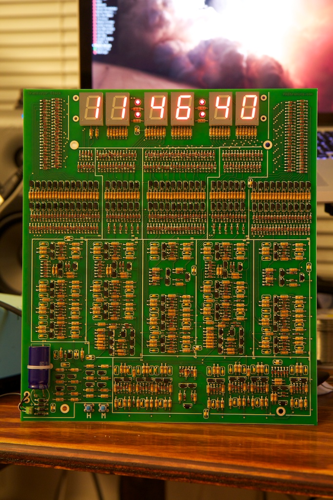
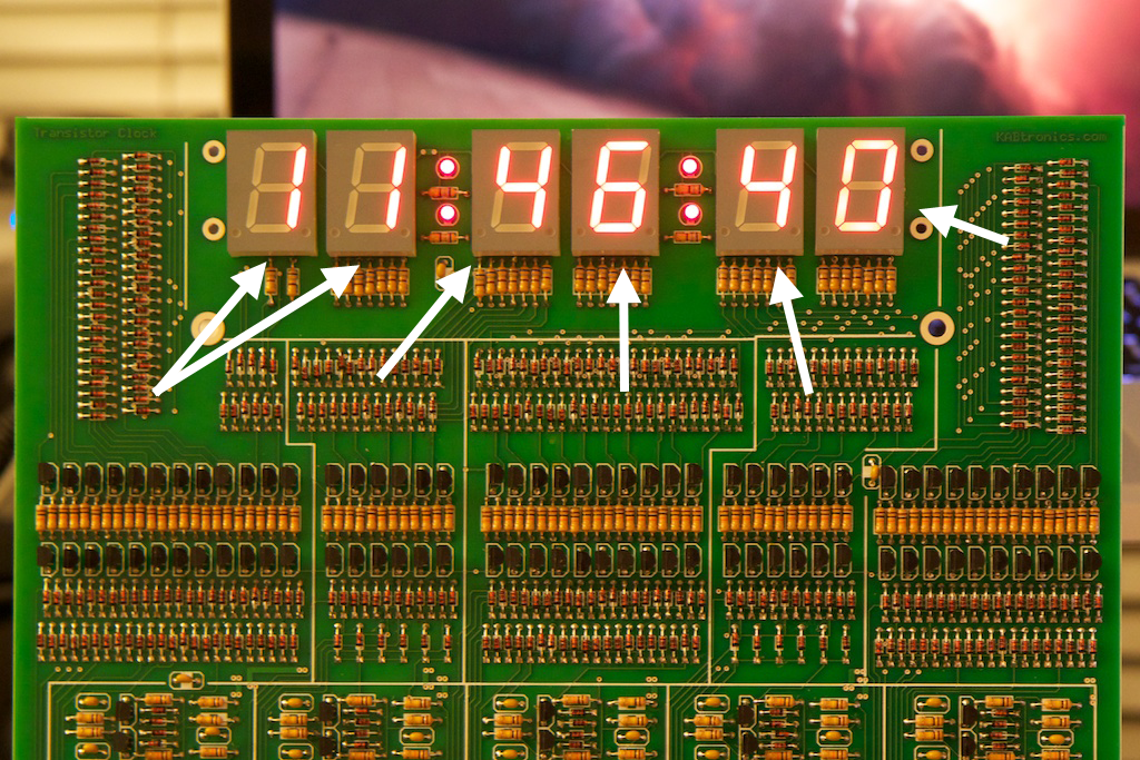
Pretty isn’t it?
Goal
We left off last time with a series of frequency dividers that could give us 1/10 and 1/6 reductions of frequency. These could be used not only to reduce the 60Hz coming out of the wall to a 1 second tick, but also to reduce that 1 second tick to a 10 second tick, 1 minute tick, 10 minute tick, and so on.
While the clock is technically already keeping time, it doesn’t do us much good if it can’t be read. The last little challenge is to turn those ticks into numbers. Compared to the last two posts, this one should be rather easy.
Binary Counter
Ordinarily, when faced with the challenge of keeping a count of clock ticks, one might use something like a binary counter such as the one I used in my Chris Jericho post. Such a device takes in a clock signal, and counts the number of ticks displaying the current count in binary on its output pins.
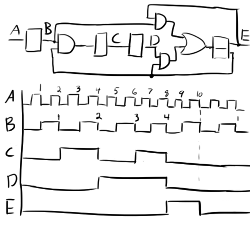
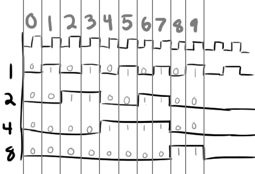
Now, you might think that creating such a device is difficult with discrete logic. It is. The good news is that we actually already created it! If you’ll remember, I mentioned in the last post that the particular method used for the clock division wasn’t the only way to do it. That particular topology was used because it gives us some nifty binary outputs.
Remember this diagram?
(If you don’t, it’s probably because I added this particular version after publishing the post)
Let’s look at it a little differently…
You mean it was water all along!?
And the 1/6 divider has a similar binary output. Now let’s make some digits.
7-Segment Decoder
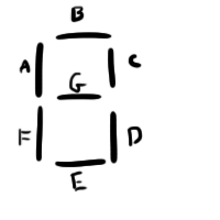
A 7-segment display is a very standard part that has been in use for over 100 years. It consists of seven panels arranged like this:
By lighting up or otherwise hi-lighting certain panels, all 10 digits can be displayed:
As you can imagine, it’s a pretty complicated process to convert a binary 0011 to the “3” you see in the above image. This is why a 7-segment decoder such as the 74LS47 is typically used.
In the discrete component world, there really isn’t any kind of trick for how to do this. You basically need to manually specify which segments to light up when the binary counter is in a particular state. This will be done using the positive and negative output of some flipflops and a crapload of AND gates.
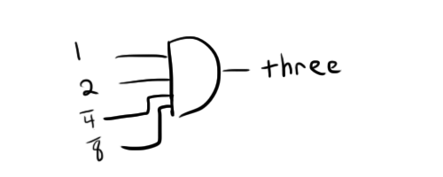
For example, let’s look at the conditions required for a 3 to appear on the display. In binary, 3 is 0011. This means that we want the 1s, and 2s place to be high to turn on the 3.
Where we assume that “three” represents the circuit that will turn on the proper LEDs (more on that later).
This particular arrangement presents an issue though. If the number “7” (0111) were to be displayed, the 1s and 2s place would also be high (along with the 4s place). So we need to make sure to account for this circumstance. Fortunately, we have the inverted flip-flop outputs for every position. If we add “not 4” and “not 8” to this AND gate, we can ensure that its output will only be high when “3” is being displayed.
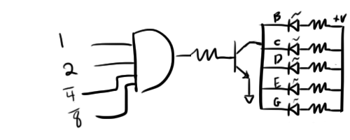
Now let’s make those 5 LEDs light up:
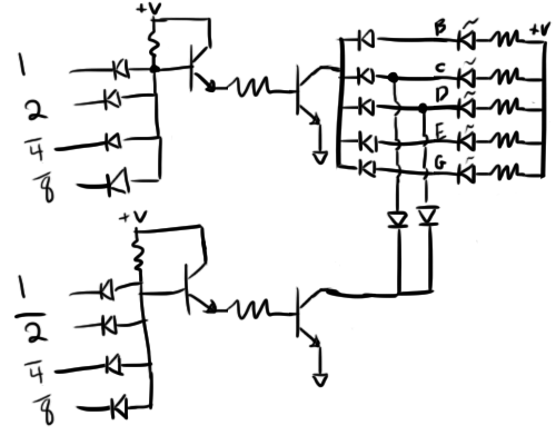
Simple enough, right? There is one problem with this design though. Because the same seven LEDs are shared across nine other circuits very similar to the one above, each LED will have several possible drains. This can cause a problem.
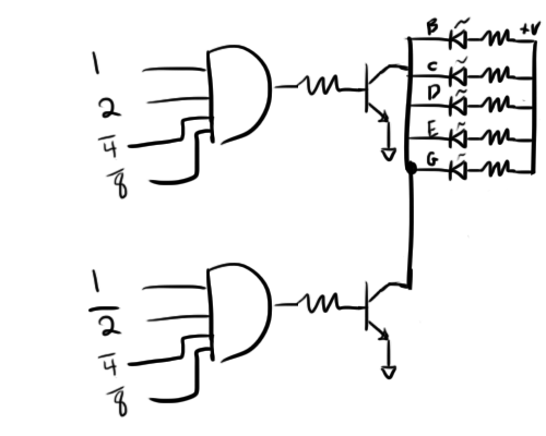
Consider the case where the above circuit is connected to the 7-segment display along with the circuit for driving the “1”.
See how they’re both driving the B and C segments? Let’s eliminate the duplicate representations of these two LEDs and combine the two circuits.
Well…that won’t work…
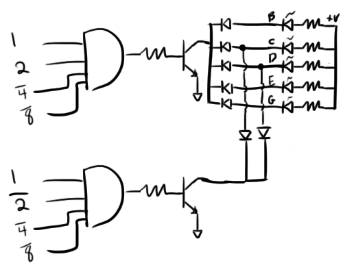
Because the cathodes of all the LEDs are tied together in this configuration, there is no way to connect the “1” circuit so that it doesn’t also turn on the “3” LEDs. We need a way to separate each LED connection. This can be accomplished with a few diodes.
So when the “1” transistor is turned on, C and D will turn on, but the added diodes will prevent current from flowing through any of the other LEDs.
So the last bit is to create the AND gate as we did in the last article:
The AND gate consists of the diodes as before along with some transistors to buffer the signal. Because the LEDs will be drawing substantial current, you want to make sure that the low-side transistor is turned all the way on.
And of course, this arrangement is repeated for all of the other possible digits.
This arrangement is incredibly diode-heavy, but fortunately, diodes are cheap and take up relatively little space on the circuit board.
Conclusion
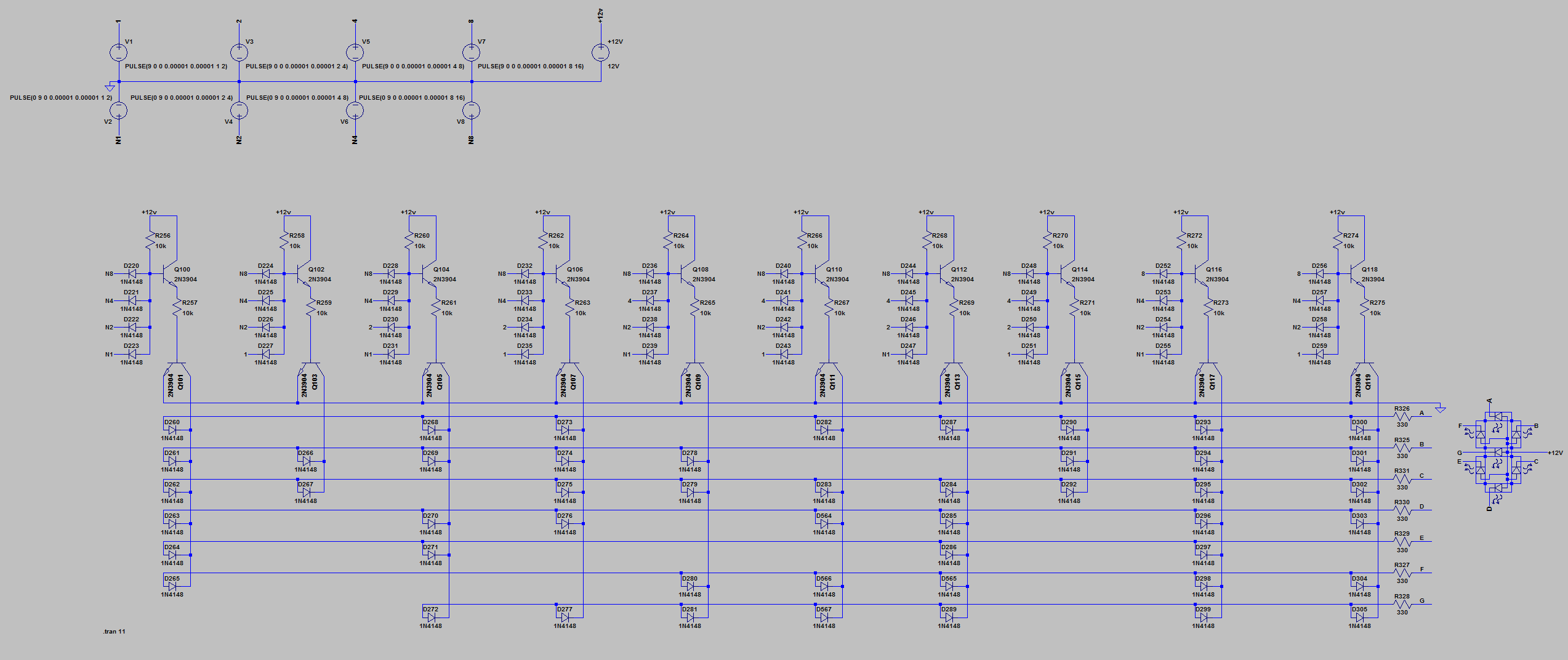
Here’s a schematic of one digit.
And the LTSpice model can be downloaded here.
That just about wraps up the clock. All of the concepts have been more or less explained. If you’d like to build your own, the kit can be purchased here.
Here’s a video of the clock in action:
You’ll note that it takes more than one clock pulse to fix the displays. This is because all of the bad initial data has to be flushed out of the binary counters.
If you really want to understand how every single part of this clock works, you can continue reading where I flesh out some of the nit picky details.
Extra Bits:
With all of the information presented so far, you can almost create a clock. There’s just two more little bits required.
- How do you handle counting to 12 for hours?
- How do you set the time?
Count to twelve
Counting to twelve is actually really easy. So far, we’ve made a circuit to count to 10 and to count to 6 and used them in a number of locations. To count to 12, all you need to do is place another flip-flop onto the front of the 6 counter.
This will double the range of the counter and shift all of the binary lines coming out of the counter up one place holder. For example, what was previously the 1’s place will now be the 2’s place. The new 1’s place is the signal being fed into the new flip-flop.
This will create a binary counter that will count to 12 and reset.
Setting the time
The time on the analog clock is set by use of two buttons located at the bottom of the clock one for hours and one for minutes. When a button is held, its respective unit of time counts up at approximately 3 units per second. The user needs only to hold this button down until the correct unit of time is shown.
The interesting thing is that this time advances exactly as it would if time were actually passing that quickly. In other words, as the minutes roll over from 59 to 0, hours increment. This is because holding that button down essentially replaces the proper clock with a much faster one, the 3Hz clock from the 1/6 prescaler.
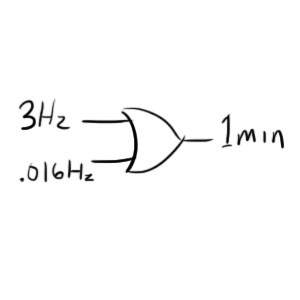
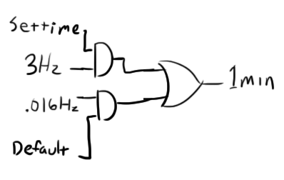
Let’s use the minutes timer as an example. The clock feeding the “1 minute” (1/60 Hz) place is fed through an OR gate along with the 3Hz clock:
Of course, both of these input clocks are ticking continuously, so we need a way to activate only the one we want. This can be done with a some AND gates.
This will work so long as “Set time” and “Default” are always inverses of each other. Previously whenever we needed an inverted signal, we used a flip-flop, but that wouldn’t really make sense here because want the time to only advance quickly when the button is held down.
There was one other time when we created an inverted signal, but it wasn’t very obvious. Take a look at this diagram of the comparator from my first post. You can see on the left, we have the “A>B” signal. On the right side of that we have a resistor to provide some hysteresis on the signal and prevent mis-counts do to signal noise. When you think about it though, the signal on the collector of the right-side transistor should be the opposite of the left side. I.e. at any point, only one of them is high.
If we create a similar comparator here where one input is a fixed threshold and the other is varied by pressing a switch, we can get just the signals we want:
Closing the switch will lower the voltage of the left input below the threshold set by the voltage divider on the right. This will cause the left transistor to turn on and pull “default low”. At the same time, “set time” will rise.
You’ll note that there are no pull-down resistors on the bases of the NPN low-side transistors. If you recall, these are only necessary for high-frequency applications to quickly turn off the transistors, and can be left out for something like this.
So that’s all there is to setting the time. Another one of these circuits should allow the user to set hours as well as minutes.






Pingback: Transistor Clock Part 2: Prescaler | ch00ftech Industries
Hello, I want to ask you, can you order this electronic kit that you have on this page? How much would it cost in euros?
Hi,
I made my own kit, it’s more universal (uses crystal instead of mains frequency for time base), it’s even bigger and has a few other advantages, and cheaper than this one. See https://mtc.mekweb.eu
Hello,
great explanations in this blog post series, thank you.
I’m trying to build some flip-flops on a breadboard (count from 0 to 5) and they are in random states when I plug in the power, just like you describe and how you show in the video.
Isn’t there a way to set all flip-flops to “zero” at the beginning?
wow, a really assembly based on transistors and diodes. I like it ! interesing to demonstrate such as process to students 🙂