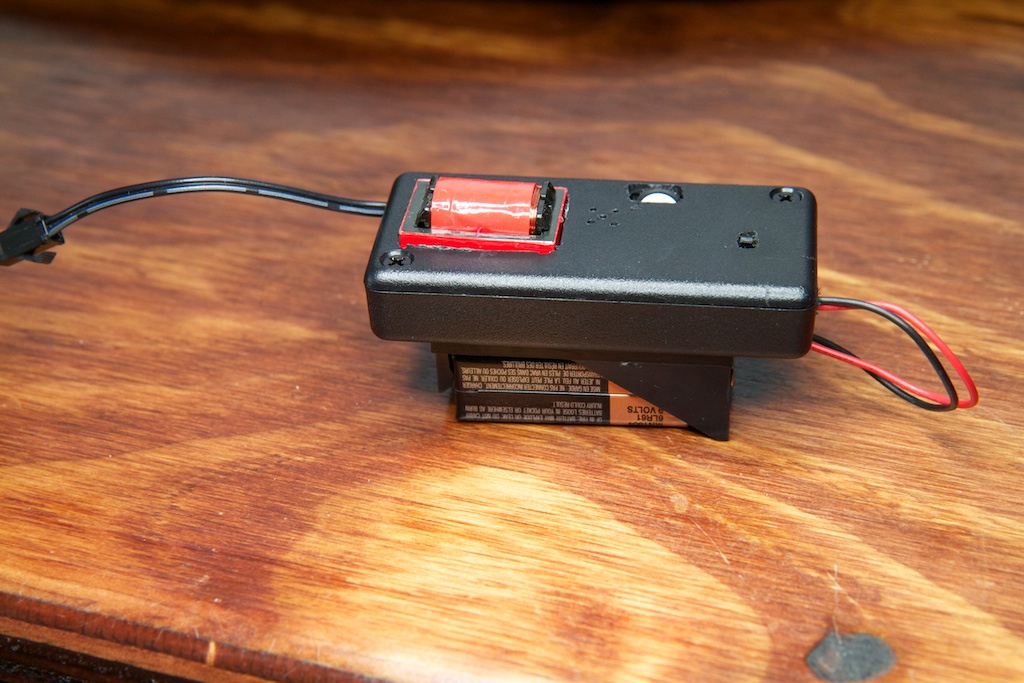
After numerous reworks of my EL dimmer circuit, I decided to rebuild the PCB and tidy it up a bit:
I think it turned out great!
Improvement
Since I spent so long on this project, I just wanted to doodle up a quick blog post to show off how much has improved over the original design and add some closure to this whole saga.
Size:
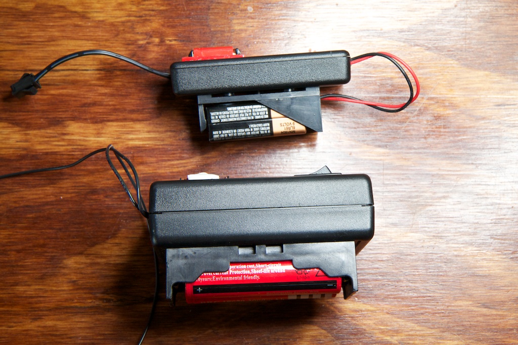
The new circuit with battery is about 1.5″x1.5″x3″ including its 9V battery pack. This makes the entire PCB and enclosure slightly smaller than just the battery pack of the previous design.
Weight
Because it uses a much smaller transformer and much smaller batteries, the new design is less than half the mass of the previous design:
This is quite a relief. For the original design, I was considering adding some kind of strap to hold the device which was too heavy to sit in a pocket comfortably. The new design doesn’t have that problem.
Performance
One of the main things I was looking forward to in writing this little update was comparing my new EL driver with my old one. One of the most striking things about the old circuit is how green the panel looked. I guess at the time I had never seen the panel lit up correctly (I didn’t have an EL driver powerful enough for the panel), so I just assumed that their definition of “white” was a little on the green side. Apparently when you illuminate white EL panels at a lower frequency, they turn greenish.
Another striking thing in the video posted below is the horrible “refresh rate” of the panel. Because I was driving it with a square wave instead of a sine wave, the panel was only emitting light for a very brief period of the entire cycle (during the clock edges). This means that it flickers at its lowest frequency settings which is strikingly obvious when that flickering battles with the camera’s image sensor producing the effect you can see in the video.
Also, because of the h-bridge on the old design, I was unable to cut power to the panel entirely; I could only drop the frequency of the square wave. I was afraid to drop it too low as DC voltage across EL materials apparently damages them, so I had to keep it running at at least a few Hz. For this reason, the panel really couldn’t get that dim even when there was no audio playing. Obviously, the new design doesn’t have that problem.
Conclusion
As I write this blog, it seems like I’m starting more projects than I’m finishing. The business card, the longboard wheels, and even the QR clock I consider to be works in progress. I’m glad to finally get this one off my desk.
My next move is going to be to contact the guy who commissioned this thing in the first place and see if he’s still interested (or even remembers me).
Bonus Video
Here’s a demo of the power supply being used to light up a piece of EL ribbon on a hoodie.
Project files can be found here: Dimming EL Panel Driver v1.0


Pingback: Sound Reactive EL Panel Dimmer (for real this time) | ch00ftech Industries
Nice improvement over the old design.
I have never been into the whole blog idea but I can’t resist myself from reading this site. The only blog that I actually enjoy. You should add more to the shop, I would willingly donate.
Thanks! I’m glad you enjoy it.
The store is a little barren at the moment, but there’s definitely more on the way.
This is really awesome! If you put one in the store, I’d buy it in a heartbeat.
The contrast between the old and the new is incredible. The new one looks really awesome! It’d be cool to see an entire outfit done with different pieces of EL wire/ribbon/panel pulsing to different frequency ranges. 🙂
Pingback: Electronic Birthday Candle | ch00ftech Industries
Pingback: DO IT YOURSELF! | DIY Electronic Birthday Candle – ch00ftech Industries
Pingback: Circuit board layout timelapse | ch00ftech Industries
Pingback: Circuit board layout timelapse » Geko Geek