This week, I learned that when it comes to power electronics, there’s no such thing as a “quick easy circuit”.
Ughhh
Party Lights
So, one of the reasons I haven’t updated my blog much recently was a move to a new apartment. I’m definitely enjoying my new place for a number of reasons, but one of the really cool features is a sort of molding that runs around the perimeter of the living room.
This molding sits about 8 inches from the curved ceiling of the room and is about a 1/2 inch wide. I had a similar molding arrangement back at school where there was some molding that ran the length of the hall that I lived on. Of course, we couldn’t just let that be, so we made this:
(The 100 refers to the name of the hall “Bemis 100” and not the number of LEDs which was well over 1600)
This system was comprised of a bunch of little hand-soldered shift-register circuits that powered a number of LEDs. When chained together, we had a giant strand of individually controllable LED lights.
Of course, we probably wouldn’t have spent all the time soldering these guys together if we had known that there was a readymade solution that accomplished exactly what we were going for.
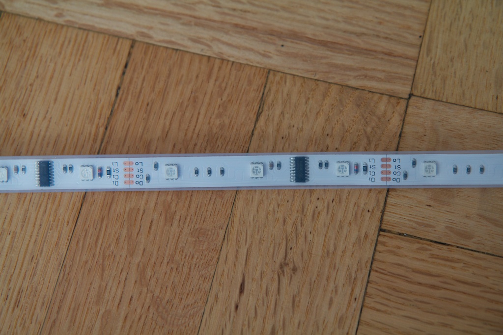
This is a strand of “Dreamcolor” LEDs. Unlike the LED strands I’ve used before, this strand doesn’t have to light up all the lights the same color. I purchased these originally for a project that required individually addressable LEDs and was disappointed to find that these LEDs can only be controlled in groups of three. Each group of three RGB LEDs can have their red green and blue brightnesses selected in software. There are also marks where you can cut the strand to fit whatever you’re trying to do.
I’ll be covering the protocol and how this all works in a later post, but some quick breadboarding got me this:
So all I had to do was glue these things to my molding, find a way to control them, and power them.
The control portion went off without hitch, and I will cover it at some other time. Power however was problematic…
High Voltage
One of the goals of this project was to make the circuit more or less invisible when not in use. The plan was to tuck the circuit up in the corner of my room and have a single cable going up to it to supply power and data. When transmitting data long distances, a simple 5V TTL bus normally isn’t enough. There are a lot of opportunities for noise to get coupled on to the data lines and introduce problems.
To avoid this, I typically use RS422. This differential transmission protocol can cancel out noise coupled on to the line and make a more robust signal. I’ve used this in the past with my wiper motor project. This solution requires a long preferably low-cost cable with at least one twisted pair. I settled on Cat5.
Cat5 ethernet cable is typically used for transmitting data over hundreds of feet in twisted pairs. Less commonly, it can also be used to transmit power. This is known as “Power over Ethernet“. PoE requires special hardware to inject power into the data lines and extract it at the load end. It’s a pretty complicated system, but the premise behind it is fairly simple.
Ethernet cable is certainly not designed to deliver large amounts of current, but it is often used to carry fairly high voltage signals such as the 90V ring of a corded telephone. Wikipedia places the maximum current per conductor of Cat5 at 0.577A, but the maximum voltage is over 100V. If I give myself two conductors for my data signal, the remaining six will give me enough copper for 1.7A at 100V.
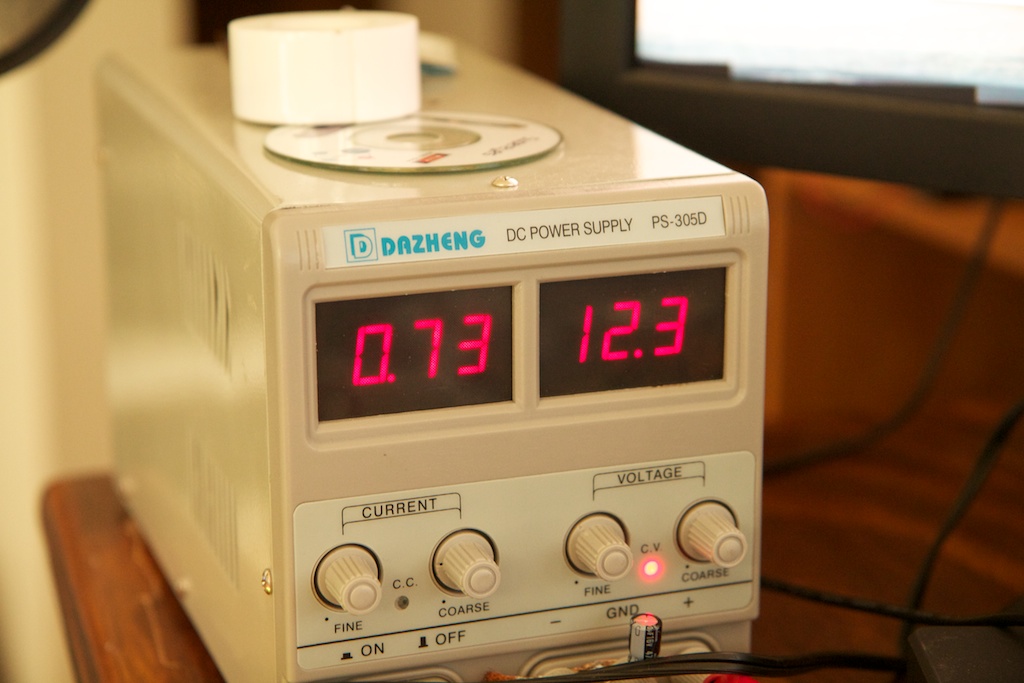
While running a test pattern, I measured around 0.7A of current at 12V for each 5 meter strand of LEDs which is about 25 watts of power total for the entire ceiling (15 meters). By stepping up to 48V, I could transmit just as much power with just 0.5A of current which was more than small enough to transmit over Cat5.
So the plan was to run 48VDC up to the ceiling of the room and then step it down to 12VDC for the lights. Conveniently enough, Digikey sells 48VDC power supplies for pretty cheap:
Messing it up
So if you couldn’t tell from the title, as of time of writing, this circuit doesn’t work as it’s supposed to. Since I clearly need a good review of the methods I tried (and failed) to use, I thought I’d write this post detailing what I should have done, and then detail exactly what I messed up.
So take notes for the first portion, and please don’t take notes for the second.
Stepping it Down
In order to efficiently step my 48V down to 12V, I needed some kind of switching step-down converter. Probably the simplest one of these is the “Buck Converter” which looks something like this:
The switch pictured to the left outputs a pulse-width-modulated current which the inductor and capacitor then low pass filter to output something resembling DC at a lower voltage. The inductor acts to smooth out the rapidly changing current of the input, and the capacitor acts to smooth out the output voltage. The diode allows the inductor to pull current from ground when the switch is opened. These types of supplies can run at upwards of 85% efficiency which is pretty good when compared to linear regulators.
Better still, as the switching frequency increases, the size of the components shrink (more on that later), so these kinds of supplies can be made fairly small.
Of course, the devil’s in the details, so for a supply like this to work, you need to have properly sized components.
Assumptions
- Input voltage = 48V
- Output voltage = 12V
- Load current = 3A
- Switching frequency = 50kHz
- Duty cycle = 1/4
Inductor
The goal for most switching supplies is to remain in “constant conduction”. In other words, you don’t want to have any periods of time where the inductor’s current drops all the way to zero. This kind of discontinuous operation can lead to a number of problems with the stability of the output.
As the 48V is applied to the left side of the inductor, its current will ramp up linearly depending on its inductance. When the 48V is removed, the current will ramp down similarly. This follows the formula:
![]()
While this current (which I’ll call
![]()
) ramps up and down, the average current will be delivered to the load.
In order to maintain continuous conduction,
![]()
should never ramp down to 0A. We need to define the exact point where it will hit 0A and size our components such that that won’t happen.
Assuming we’re already in continuous conduction, the beginning and end of each cycle must happen at the same current level (we’re assuming that it’s in some kind of steady state and that there are no transients). This means we only need to analyze either the ramp up or the ramp down. I chose ramp up for this discussion.
Doing some geometric analysis, you’ll notice that
![]()
(the average) will always sit halfway between the upper and lower extremes of
![]()
. So in order for
![]()
to never reach 0A, the peak must be
![]()
or twice the load current.
![]()
Where
![]()
represents the current ripple or the difference between the maximum and minimum current.
Using this information, we can size our inductor. We know that during 1/4 of the switching cycle, the current will be ramping up, and we want to make sure that that ramp up (
![]()
) is less than twice the load current (3A). We can also assume that the output voltage is already steady at 12V, so the voltage across the inductor is the input minus the output.
![]()
![]()
![]()
![]()
![]()
![]()
![]()
![]()
From this, we know that L must be larger than 30 microhenries.
Additionally, we need to make sure that the inductor can handle the current load. The inductor I chose saturates at 4A. This means that above 4A, its inductance drops off dramatically. I figured that if I chose a larger inductor than required, I could probably get away with this. More on that later.
Picking a regulator
Before I started doing all of this math, I had already picked out a switchmode controller that I liked, the LM2576HVS-12. This regulator acts like the switch in the above buck converter doodle. Just select the inductor, capacitor, and diode, and it will output a steady 12VDC. The datasheet claims that it operates at just over 50kHz which is why I used 50kHz in the above calculations.
Another cool feature is that it’s able to maintain its output voltage in discontinuous operation. That means that if
![]()
drops too low, the regulator will still maintain 12V output. This is very inefficient though and should only be used for low-power situations.
Looking on the first page of the datasheet, I saw this graphic:
Although this was for the 5V version, and the input voltage was different, I saw that they were using a 100
![]()
H inductor and thought I’d round my own up to 100
![]()
H.
Being lazy, I figured I’d eschew the math and just pick a 1000
![]()
F capacitor for the output cap.
Capping it off
For the sake of this blog post, let’s work through the math that determines what kind of capacitor value is good.
In reality, a capacitor isn’t entirely necessary. In fact, the inductor isn’t even necessary for some applications. The only purpose of the cap is to even out the output voltage, so in order to determine what kind of cap you need, you first need to select a desired output voltage ripple.
For this application, let’s arbitrarily choose:
![]()
This capacitor will need to absorb all the extra current when
![]()
rises above
![]()
, and provide extra current to the load when it drops below. In other words, the cap will shunt the AC component of the output to ground.
So all you need to do is determine how much current will make it into the cap and how much the voltage will change as a result. A cap’s voltage changes linearly with respect to its stored charge, so we first need to figure out how much charge is stored.
As stated before, we’re assuming the device is in steady state, so whatever charge enters the capacitor on the upswing must leave it on the downswing. For this reason, I only need to look at half of a cycle to determine what the current ripple will be. Integrating the current ripple will tell us how much charge enters (and later exits) the capacitor:
This works out to:
![]()
![]()
This is for
![]()
which is the case for L=100
![]()
H.
So long story short, we want the capacitor’s output to change by less than .1V when 4.5
![]()
C of charge is dumped into it. For this, we use the home shopping network equation:
![]()
![]()
![]()
So in order to keep the voltage ripple down to .1V, we need a 45
![]()
F capacitor. 0.1V is a pretty generous value for current ripple. A lot of supplies go as low as 20mV ripple which would require a capacitor in the hundreds of microfarads. There’s no harm in adding some extra capacitance, and the schematic from the datasheet shown above shows a 1000
![]()
F capacitor, so I decided to go with 1000
![]()
F.
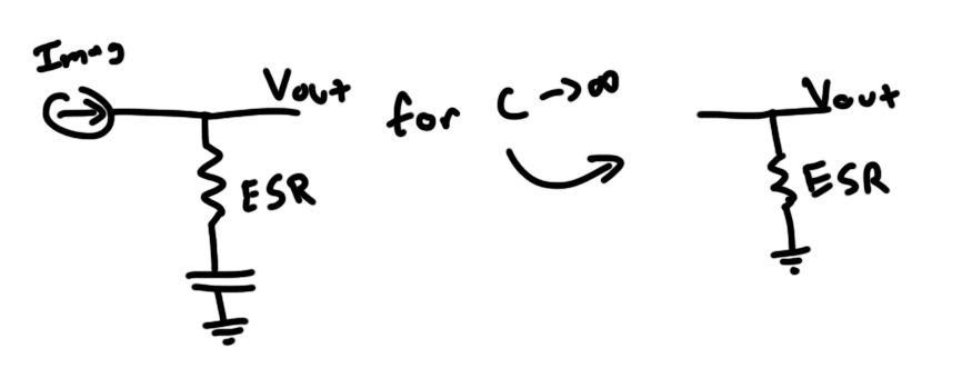
An advantage of going with such a large capacitor is that it drops the capacitive impedance presented to the AC component of the current close to zero. This means that the impedance of the cap is primarily due to its Equivalent Series Resistance (ESR). Most caps have an ESR rating which can be modeled as a resistor of that value in series with an ideal cap (duh). As the cap’s value gets very large, we can model the circuit like this:
Note that this only models the AC function of the circuit.
So with this simplified version, you can easily determine the output voltage ripple due to the ESR of the capacitor:
![]()
Assuming the ripple due to the capacitor is negligible, let’s determine an ESR that gives us 0.1V of ripple:
![]()
Diode
The purpose of the diode is to allow the inductor to continue to conduct even when the input switch is opened. Inductors “don’t like” to have their currents changed rapidly, and will induce an electric potential to keep current flowing as their energy-storing magnetic fields collapse. Without the diode, the inductor would generate a very large voltage that could potentially damage the switch (also, the circuit just generally wouldn’t work).
Selection of the diode is fairly simple. It needs to be able to tolerate the reversed biased voltage presented to it. In this case, that’s 48V while the switch is closed.
It also needs to be able to conduct enough current to keep up with
![]()
. For the most part, you only need to worry about
![]()
as most diodes will have a higher instantaneous current rating than DC current rating anyway.
Finally, you want your diode to be efficient. All diodes have a forward voltage drop. As current passes over this voltage drop, energy will be dissipated. The lower the
![]()
, the less energy is wasted. Most silicon diodes have a
![]()
of 0.7V while Schottky diodes drop much lower.
Additionally, Schottky diodes are sometimes called “fast recovery” diodes because they are able to switch on and off quickly. Silicon diodes often have a small amount of capacitance charge built up in their junction that needs to be removed before they will block reverse current. This will cause them to draw current in reverse for a small period of time every time they are reversed biased. This pulls current away from the load and places a heavier burden on the switch.
So that wasn’t that bad, how’d you mess it up?
So…right.
Starting out, I wasn’t too excited about this project because it’s really not anything super new. These lights have been used everywhere, and it isn’t difficult to find pre-made solutions that do exactly what I’m trying to do. I mostly added the buck converter as a way to make this project somewhat more challenging/interesting.
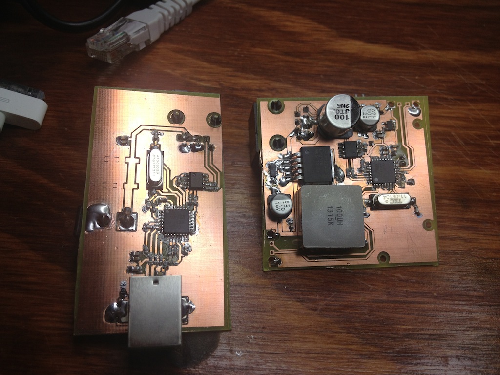
Unmotivated, I definitely didn’t spend enough time with my head “in the zone” to vet out all of the decisions I was making during the design of this device. I came up with two PCB designs, ordered parts, and quickly assembled them:
The circuit on the left connects to the 48VDC supply and to a computer over USB. The onboard FTDI serial interface chip and RS422 converter take the data from USB and pass it through ethernet along with the 48VDC. The circuit on the right accepts the 48VDC and steps it down to 12V for the LEDs and then down to 5V with a linear regulator for the onboard AVR. The idea is for the AVR to take frames passed to it over ethernet and move the data out to the LEDs.
Here’s a collection of things I messed up:
Diode Selection
I really don’t know how I mixed this one up so bad. For some reason, I selected the SS3P3 Schottky diode from Vishay. I guess I got the Schottky part right, but a quick glance at the datasheet should have shown me the vital 30V reverse bias voltage limit. I guess at the time, I was thinking that the diode would only be exposed to the output voltage. I have no idea why I thought this, but a 30V diode will not last long in a 48V circuit.
The diode actually held up for maybe 30 seconds, but then it promptly burned out. I went through 5 diodes this way. Interestingly, at one point, I tried working two diodes in series so that they’d each only have to handle 24V, but they also burned out in a similar fashion. I’m guessing that that’s due to the heat dissipation issues associated with a power diode floating over the board with no copper to pull the heat away. It could also been because 12V wasn’t enough of a safety margin.
Capacitor Selection
So I made a few mistakes here. You’ll notice on the left PCB up there there are two locations which look like they could hold SMT caps. These are there because I somehow forgot about capacitor voltage limits while selecting and placing those caps. Those footprints are for 16V caps which would explode the second I connected them to the 48V supply rail.
On the output side, I made a few mistakes. Firstly, I budgeted to have two 1000
![]()
F capacitors, but somehow messed up my parts library and ended up placing footprints for 100
![]()
F caps thinking they were 1000
![]()
F. This error carried through to my order, so I never ordered the 1000
![]()
F caps.
Still though, 200
![]()
F of capacitor should have been large enough to handle my voltage ripple (I only needed 45
![]()
F, remember?). Unfortunately, I didn’t think to even look at the datasheet for these caps:
The layout of the datasheet is a little vague. There is no listed ESR, but the rated ripple current is either 23 or 18 milliamps. Considering my math shows something like 1-2 amps of ripple current, these caps don’t stand a chance.
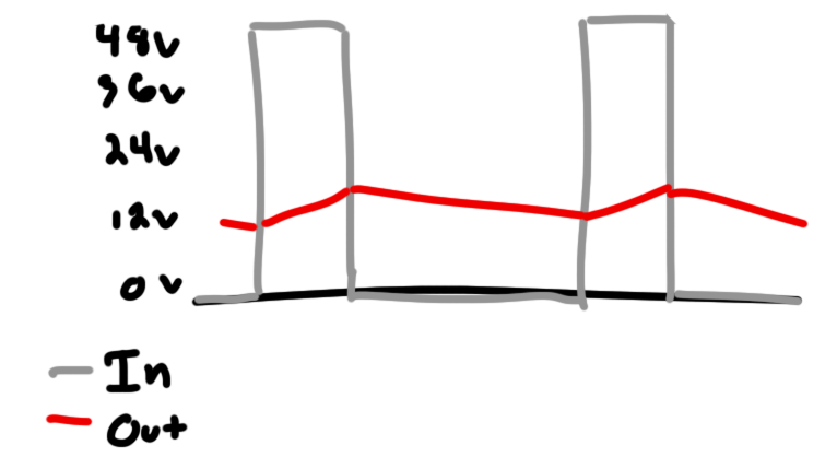
That’s why the amount of voltage ripple on the output shouldn’t be a surprise:
That’s 1.35V peak to peak.
Interestingly, the frequency here is almost half the rated 50+kHz. I’m guessing the regulator is in some kind of special mode as a result of the crazy output voltage swing.
Attempts to fix it and reading the datasheet more closely
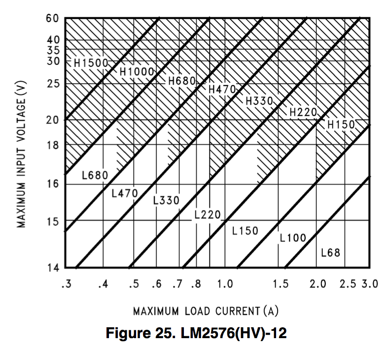
So when my circuit kept blowing up, I made a few attempts to fix it. As shown in the header image to this post, I tried at one point to add a larger inductor (which I pulled out of my failed EL wire power supply). This was after looking closer at the regulator datasheet where I saw a plot that’s supposed to help you size your inductor:
This plot would seem to indicate that I should use a 220
![]()
H inductor. I’m still convinced that this isn’t necessary. I connected my multimeter in series with the 100
![]()
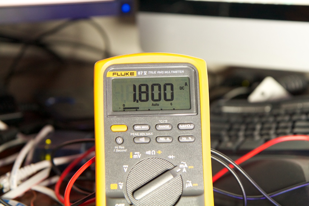
H inductor and took a measurement of the AC and DC current flowing through it with a 1.8A load.
0.541A is the RMS of the AC current passing through the inductor. In order to convert this to
![]()
, I need to convert the RMS current into the peak to peak of a triangle wave. This can be done by multiplying by
![]()
. This works out to just under 1A. This seems to be just in line with predictions. I said earlier that we’d have 1.8A of ripple for a 3A load, and here I’m getting 1A of ripple for a 1.8A load.
I’m skeptical, but I’ve ordered a 220
![]()
H inductor just in case. For all I know, there’s something weird about this particular regulator that requires an especially large inductor.
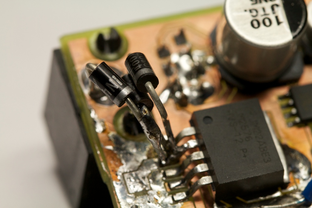
In order to get some of the measurements for this post I had to replace my burned out Schottky diodes with the only diodes I had on hand, 1N4001s:
These are rated for 50V but only 1A, so I had to place three of them in parallel. Even with this parallelization, they heat up really fast, and I can only keep the circuit running for a few seconds at a time. This is because they are very slow diodes that are not meant for high frequency applications. This is where that “fast recovery” thing comes into play.
I guess I shouldn’t have been surprised with the results when I discovered this line in the datasheet specifically calling out the 1N4001:
I’ve ordered some new diodes which should get here along with the inductor.
As for the capacitors, they heat up immediately after power on. I’ll be ordering some new high current caps as well while I’m at it.
Bad Ass-umptions
I was a little upset to discover that even with all of these updates, the entire execution of this concept is flawed. Before, I talked about the current draw per 5m LED strand being 0.7A. I derived this number by watching the current of the strand while running a little scrolling rainbow pattern routine that I wrote.
Unfortunately, I somehow neglected to note that the color white is tragically left out of the rainbow. White involves all three colors, and is the worst case scenario from a power draw standpoint. While I had originally assumed a current draw of 0.7A per strand, the actual current draw is 1.8A per strand.
This means that all three strands add up to 5.4A which is way beyond the 3A maximum output of this circuit. Furthermore, at 12V, the lights will draw around 60W of power. My 48V supply can only output 1.25A which places it just barely at 60W and not nearly high enough to work once conversion losses and safety factor are taken into account.
DANG
Conclusion
So, yes, the circuit isn’t currently working, and even if it was working 100% as designed, it was still designed under bad assumptions and will never function as intended.
I think my next step is going to be fixing up the circuit so that I can at least demonstrate it powering a single strand. Then I’ll come up with a better simpler solution for what I’m trying to accomplish.
If I just ditch the ethernet idea, it should be trivial to run 12VDC around the room. I can even spread out multiple taps to take care of resistive losses in the power lines. This might even let me keep the ethernet , so I don’t have to throw away the circuits I’ve made. By spreading out the power draw to multiple cables, I might come in just under the ethernet spec.
In other words, YOU CAN’T STOP THE PARTY!











1) Consider a synchronous controller. Given your current requirement, I hate to see all that power loss in the diode(s).
2) If you’re still looking to parallel some diodes, I hope you went for ultrafast versus schottky. Pay attention to what happens to a schottky at higher temps and how that’s a bad thing when paralleling them.
You mention initially the capacitance of silicon as being a bad thing, but you might be misspeaking. For a silicon diode, you have the reverse recovery time which is not a factor of any sort of capacitance, but intrinsic to the material. This reverse recovery time adds to your AC losses. For a schottky diode, the body capacitance becomes the factor for AC losses.
At 52kHz switching, an ultrafast should be fine.
3) Missing from the datasheet is a feedback bode plot or a desired roll off frequency for the LC. Even in the “design procedure”, they mention the LC being the dominant pole, but don’t give you a design target. With design examples of 100uH and 1000uF, it’s ~500Hz. With 100uH and 200uF, it’s at 1.1kHz. Might be the issue; not sure.
4) Given the drop in operating frequency and the ripple, my guess is that it’s always in DCM and barely getting in to CCM if at all. It’s maintaining your 12V, but it’s trying like heck to do so. Have a low value high power resistor you can insert in line with the inductor to view the current waveform?
Hey Ken!
Thanks for the input.
1) Eh, it’s only a 3A supply. I wouldn’t consider anything else for higher power as I’ve done before. Yes, the diodes got scorching hot, but they weren’t the right diodes. Replacing it them with a Schottky dropped “scorching hot” to “uncomfortably warm”.
2) Those diodes were just a stopgap so I could diagnose some of the other problems with the parts I had on hand. I had already burned out all the Schottkys that I had ordered, so I moved to the only parts I had on hand. Ordering a better Schottky solved the problem.
Maybe it’s not a capacitance per-se, but the diode will not achieve its reverse current blocking capabilities until the mobile charge in its junction is depleted. This can be modeled as a capacitance, albeit one where it changes as a result of the size of the forward current, etc. I’ll change the wording to be more clear.
3) I ended up getting it working with those values, so I don’t think that was the problem. Definitely something I didn’t check for though.
4) I unfortunately wasn’t able to get a trace of the inductor current, so I’ll never know for sure. I was mostly concerned at the prospect of accidentally applying 48V (or worse) to my o-scope. The reading from my DMM seemed to indicate that it was …pretty high.
Thanks for the input. I’ll be writing up all of my progress soon.
Pingback: Finally, party lights | ch00ftech Industries
Pingback: Electrical Hell and the apocalypse survival external phone battery | ch00ftech Industries