

Introducing the Tesla P0.00296!
0-60 in 2.8 seconds…if you drop it off a cliff.
Motivation
The annual Pinewood Derby in my Cub Scout troop was always an exciting time for my friends and me growing up. Just look how happy I am in this amazing digital photo composition that my dad put together using Microsoft PictureIt! 99:

Hey man, it was 1999. We’re lucky it was digital at all.
There are a few important things to note about this picture. Firstly, I’m in first place. Obviously. Secondly, there are only three cars racing. This is because our track was a terrible hand-built wooden number, and the 4th lane was known to give an unfair advantage to the racer.
Pinewood Derbies have changed a lot since then. Tracks are now better crafted and have electronic systems to measure track times down to the millisecond. There are even services available where you can hire a team to set up a professional pinewood derby track for your event.
My office does exactly this every year.

Last year, I used my CNC mill to aid me a little bit in carving out my car:

Okay, maybe a little more than a little bit. Sadly, because I had to use five blocks to make this monster, the car came in way above the 5oz weight limit even after I removed a bunch of material from the bottom:

This means it had to race in the “unlimited” class along with a boot, my cousin’s Volvo, and a slug of steel turned down to two razor sharp wheels that suffered some stability problems half way down the track:
 I managed to win this particular heat, but I ultimately didn’t take home gold.
This year, I wanted to try something different. Unlike my scout troop’s hand-painted track, these new fancy tracks are made from aluminum. By exploiting a little physics, I was hoping to give myself the upper hand.
Induction motors (the easy explanation)
Brushed DC motors are great for small electronics due to how easy they are to operate (just apply a DC voltage and away you go), but when it comes to large industrial machines, their brushed contacts can wear out quickly, and their permanent magnets can be expensive.
That’s what makes induction motors so great! They contain nothing but steel and wire, can be controlled fairly easily, and in the case of stationary machines, they can be driven directly off three phase power from the wall.
The simplest way to describe how an induction motor works is using the old copper pipe and magnet trick.
Due to Faraday’s law, a changing magnetic field through a loop of wire will cause a current to flow in that wire. In this case, the solid surface of the copper pipe acts like little loops of wire, and “eddy currents” are generated in this surface. These eddy currents in turn generate a magnetic field (Ampere’s law) which opposes motion in the magnet. Generally speaking, loops of wire (inductors) really really don’t like it when magnetic fields change magnitude or direction and they generate a current or a force to try to prevent this.
Now, if you look at this copper pipe example, you can imagine that by connecting a string to the magnet and holding it steady, you could also show that the pipe would fall slowly down around the magnet. Taking it one step further, if you were to suddenly jerk the magnet upwards, you could potentially get the copper pipe to move upwards as well. It wouldn’t go as fast as the magnet, but it would still move in the same direction. If you were to fix the magnet to a spinning disk (the stator) and place that disk near a copper disk (the rotor), the copper disk would rotate.
This is more or less how an induction motor works, but rather than physically moving a magnet around, a series of electromagnets are pulsed in a sequence to keep the magnetic fields rotating. Also, instead of a copper disk, real induction motors use coils of copper wire in their rotor to improve their performance and efficiency.
Linear induction motors (the hard explanation)
So if brushed DC motors are so great for small electronic devices, why would I go with an induction motor for my car? Well, going into this experiment, I knew that the track was made from some kind of metal. I had a pretty good feeling that it wasn’t steel, because a 30 foot long steel track would be a little ridiculous to carry around. It was probably aluminum.
Rather than arranging my motor to rotate the wheels, I wanted to use the track as my “rotor” and create a “linear induction motor.” This is a little counter-intuitive because in this case the stator (car) is moving while the rotor (track) is stationary. This configuration generates a force sort of like the force generated on the copper pipe in the thought experiment above.
Aluminum is a pretty good conductor like copper, and more importantly, unlike steel it’s non-ferrous. When cut into specific shapes, steel is great for directing magnetic fields where you want them to go, but when in a solid block, it tends to dissipate them.
In its simplest form, my motor design looks like this.

The stator of my motor consists of a bunch of loops of wire wrapped around a saw-tooth shaped ferrite core which is there to help direct the magnetic fields towards the track. The top portion of the diagram is drawn looking up at the bottom of the car while the bottom portion gives a side view of the motor facing down towards the track.
The wire is wrapped in six loops that are connected in series into three separate “phases.” These phases are represented by the three colors. The little arrow on the loops at the top indicate the relative direction of the phases. If current is traveling in the direction of the arrow on one of the black loops, it’s also traveling in the direction of the arrow on the other. Note that the direction reverses between two loops of the same color.
The left side of the diagram shows how the three phases are connected. This is called a “Wye” configuration (Wye goes along with “Poynting” as one of my favorite aptronyms). Basically, theres a single point where all three phases connect. The other side of the three phases connect to whatever is driving the circuit. In the case of a large industrial induction motor, this may be connected directly to three phase power. In my case, I built a little driver for it, but more on that later.
Now let’s try firing this guy up to see what happens. First I’m going to push current into the black phase and out of the red phase.
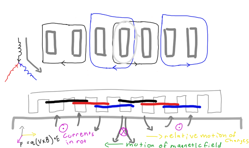
As you can see, the red and black phases overlap and their currents are moving the same direction (this is because the current is moving opposite the direction of the arrow in the red phase).
Next up, let’s switch to down black and out blue:
Here’s where things get a little weird. As you can see, shifting the motor phase has the effect of moving all of the magnetic fields one notch to the left. This is where Lorentz forces come into play.
The Lorentz Force says that when a charge is moving with some velocity through a magnetic field, it will feel a force in the direction of the cross product of its velocity and the field (i.e. point fingers of right hand in velocity direction, curl in field direction, thumb is in direction of force).
The important thing is that for that equation to work, the charge’s velocity has to be defined relative to the field. In this case, because the field is moving to the left, the math works out as if the charge is moving to the right through a stationary field. If you apply the right-hand rule, you’ll see that the charge will begin to form currents in the the rotor in the directions indicated in purple. A circle with an X indicates that the charge is moving into the page while a circle and a dot indicates it moving out of the page.
Finally, focus on one of these currents and run the right-hand rule again.

You can see that a force will act on our charge that pushes it in the direction of the moving magnetic field. This is more or less what we expect from our thought experiment with the rotating permanent magnet.
The phases of the motor continue to be energized in this manner for all six possible configurations and then start over:

If you work out each phase, you’ll see a general pattern of North and South poles moving in sequence over time.
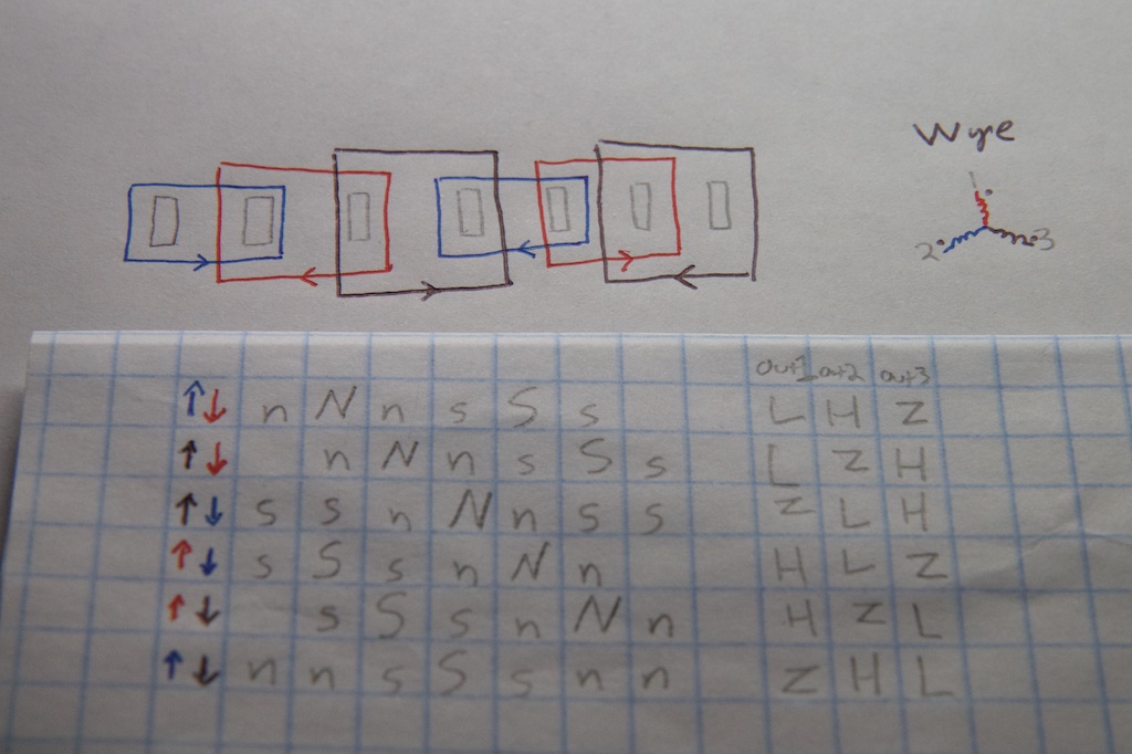
If the motor had absolutely no friction or load on it, eventually the relative velocity of the charges in the rotor and the magnetic field would be zero and the force would drop to zero. Realistically, this never happens and there is always some amount of lag or “slip.” The amount of slip present determines the amount of torque generated by the motor.
Table of contents
- Motivation and induction motors
- Building and Optimizing the motor
- Building the car
- Results and conclusion
I’m curious as to whether your firmware could’ve been improved further by refactoring the interrupt. Because interrupts must not change the state of the chip, the routine begins by pushing every register it uses onto the stack, and ends by popping them back off. The compiler is pretty bad at reducing number of registers used, so complex interrupts may have an overhead of about 30 cycles(15 registers, pushed and popped), about 2us at 16MHz, per interrupt.
This could be improved by reducing the complexity of the ISR, programming it in assembly, or by abandoning the interrupt and refactoring the timing-critical code into the main loop.
I’m not sure what your code looked like at this point, or what kind of timing requirements you had to meet at your fastest frequency, but I imagine that it could be possible.
Oh yeah, I’m sure I could have done a lot to make it faster. I’ll upload the code and design files tonight if you’re interested. I’ve only done assembly on the 8051, and I didn’t have enough time in this project to figure all of that out for the AVR, so I opted for more coils/slower frequency. Based on the measurements I took, I’d need to get my switching down to something like 5us per interrupt if I wanted to make it work with the smaller coils.
Neat project!
Your best bet on AVR is to just unroll the switching (you only have 6 steps — explicit code is way smaller than accessing data) and don’t even bother with interrupts. You can use a timer to set the overflow flag or similar, but you can just spin on that flag and clear it from software (write back the value you read) rather than even bothering with jumping to the vector, setitng up the stack, etc.
That being said, I do software PWM very similar to yours at much higher speeds with interrupts, but written in assembly, and with some tricky tricks like using “ijmp” as the interrupt vector. Doing that from C would be particularly fun. Last I experimented with naked interrupts on AVR, GCC would like to emit random moves to unused registers at times, making it very difficult to manage your own stack unless you just inline-assembly the whole thing. You can, however, reserve registers for this purpose, which is nice.
Nice job. I enjoyed reading it. You should test the motor again with the aluminum piece but use a piece of wood or plastic to give you a bigger gap between the motor and aluminum. Then you can see how much the bigger gap affected things.
Great job, and I’ll bet the winning car didn’t pass emissions!
>The strange thing is that it only ever used 17% of the processor and if I started another instance at the same time, it would take another 17%.
100/6 = 16.6667
It was a single threaded task, so it could only use one core.
Pingback: Bookmarks for October 13th | Chris's Digital Detritus
Pingback: TECNOLOGÍA » Lorentz forces and cheating at the Pinewood Derby
It kills me that you have to drop your voltage from 20V to 10V! Use a hardware timer (if available) to generate a 100 kHz PWM (if you can) to wave-shape the current and you wont need to! Your ultra-small inductance is working against you here.
DRV8313 is my favorite motor driver.
–Matt
I’m actually already using the hardware timer, but it’s a pretty complicated waveform to generate entirely with hardware timers (three phases and all that), so I ended up just increasing the number of turns.
Pingback: Ultrasonic parking sensor | ch00ftech Industries
Pingback: Lorentz forces and losing the Pinewood Derby | ch00ftech Industries
Pingback: Animated EVSE | ch00ftech Industries
Good web site you’ve got here.. It’s hard to find good quality writing like yours these days.
I seriously appreciate people like you! Take care!!
Pingback: Ultrasonic parking sensor • Tech Projects
44fy57
t8dolk
ifqoj4
a171f2
y9w73v
c4vw64