
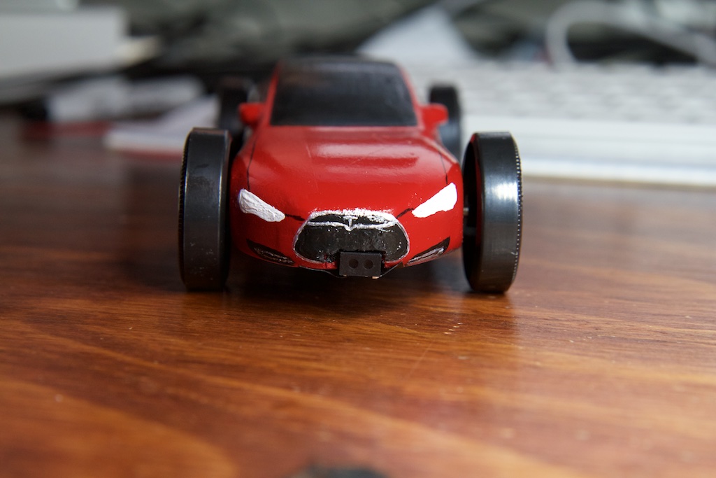
The car
A great man once said “If you’re going to build a time machine into a car, why not do it with some style?”
Over the years I’ve used this blog as a means to improve my skills as an engineer, but more recently, I’ve been trying to improve my marketing skills as well. I figured that the best way to get people interested in an induction-motor powered pinewood derby car is to model it after a real life induction-motor powered car: The Tesla Model S.
Step 1 in making a Model S pinewood derby car was finding a digital model of a Model S. Hell if I was going to make one myself. I found one on Thingiverse and imported it into Viacad.
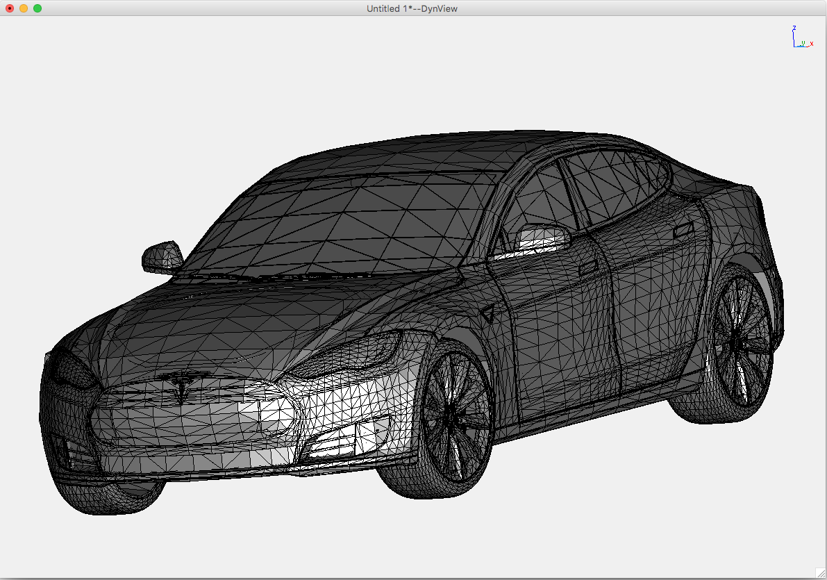
Now, the thing about Pinewood derby car kits is that they have super weird proportions. The blocks measure 30x45x175mm which makes them way narrower and way longer than just about any real car. I got around this with the Lambo last year by using multiple kits to make the body of the car wider than the wheelbase, but I wasn’t really up for all of that work this year and I still wanted a chance at getting under the 5oz weight limit.
So it was just a matter of shrinking the S down until it fit within the wood block.
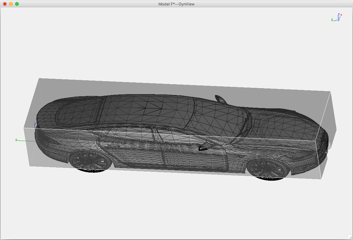
Elon’s going to have to lose a few pounds if he wants to fit into this one.
I lined the bottom of the S up with the bottom of the block, and the widest part of the body with the edges of the block. I ignored the rear-view mirrors figuring that I could add them later with clay or whatever if I wanted.
Next up was fitting all of my stuff inside. I built a simple 3D block model of my circuit board, motor coil, batteries, and front-facing sensor and placed them inside the car to see if they would fit:
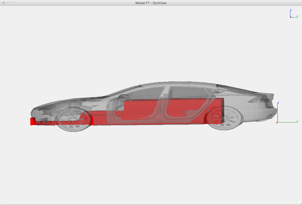
Roomie!
Subtracting the blocks from the original wood block gave me my first CNC job.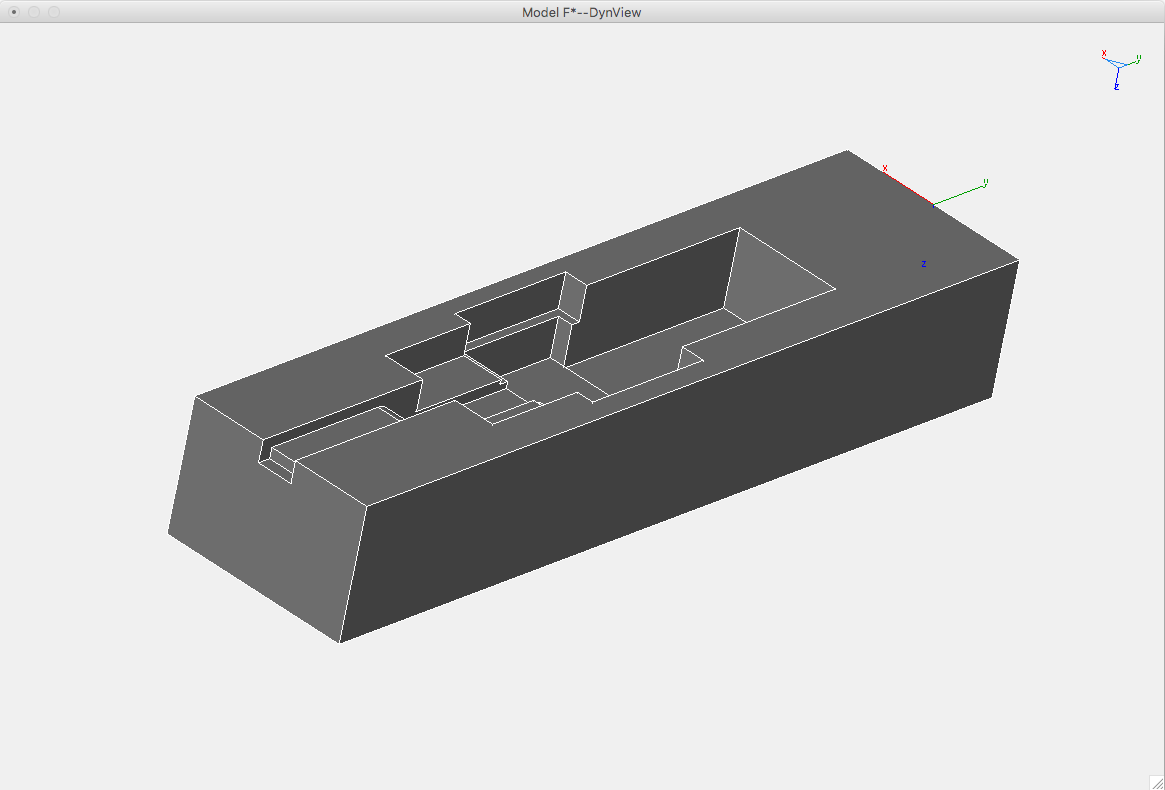 This was a pretty easy job for CamBam that used a 1/8″ bit in a 3D profile task.
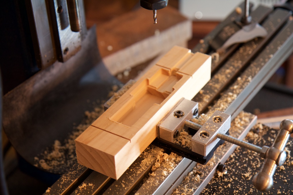
I somehow managed to get it about 1mm off-center which is a shame, but shouldn’t affect the performance of my motor. I did have to hand-modify the channel going to the optical sensor in the front to get it centered again, but it wasn’t a big deal.
Next up was the top.
This job was performed with a 1/4″ end mill with a 0.8mm step waterline rough job and a 0.1mm waterline smooth task. You can read about the difference here. Considering how the design didn’t have any flat surfaces, I probably could have gotten away with just the smooth pass.
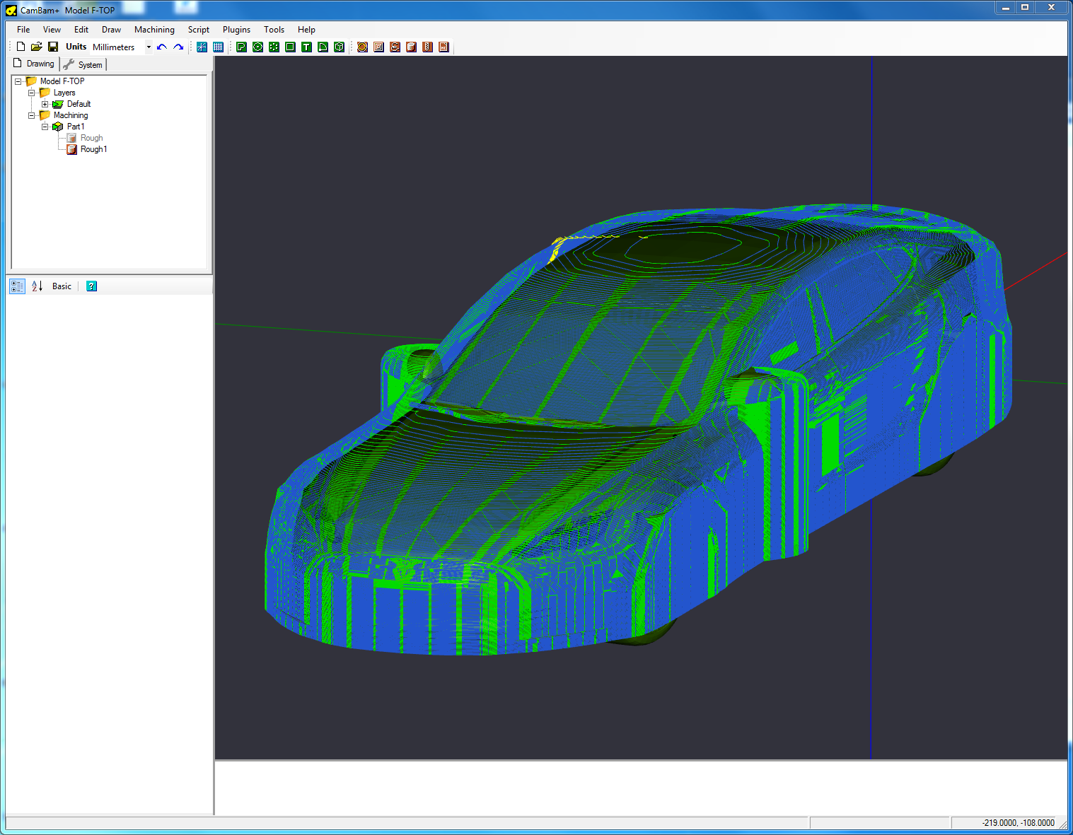
I had a little bit of trouble getting the smooth pass to work. Firstly, I had to turn off “backface culling” because the “direction” of the Tesla 3D model was wrong (I have no idea what this means). Secondly, for whatever reason, it took a LONG time to process. Even with 16 gigs of ram and 6 processor cores, it took literally fifty minutes. The strange thing is that it only ever used 17% of the processor and if I started another instance at the same time, it would take another 17%.
To fixture the block, I used some double sided tape, and resorted to using a bit of wood glue on the corners when the block started to lift up early in the job. Either way, I was super paranoid that it was going to move and get ruined, so I ended up holding the block down with a nervous finger for almost the entire two hours…
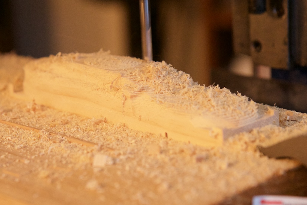
As you can see, the 3-axis CNC mill is incapable of cutting under things, so the mirrors have a “shadow” underneath them. This was actually beneficial because modifying STL files with Viacad is a nightmare, and I needed a flat surface under the wheel wells to mount the pinewood derby wheels where the Model S wheels would have been.
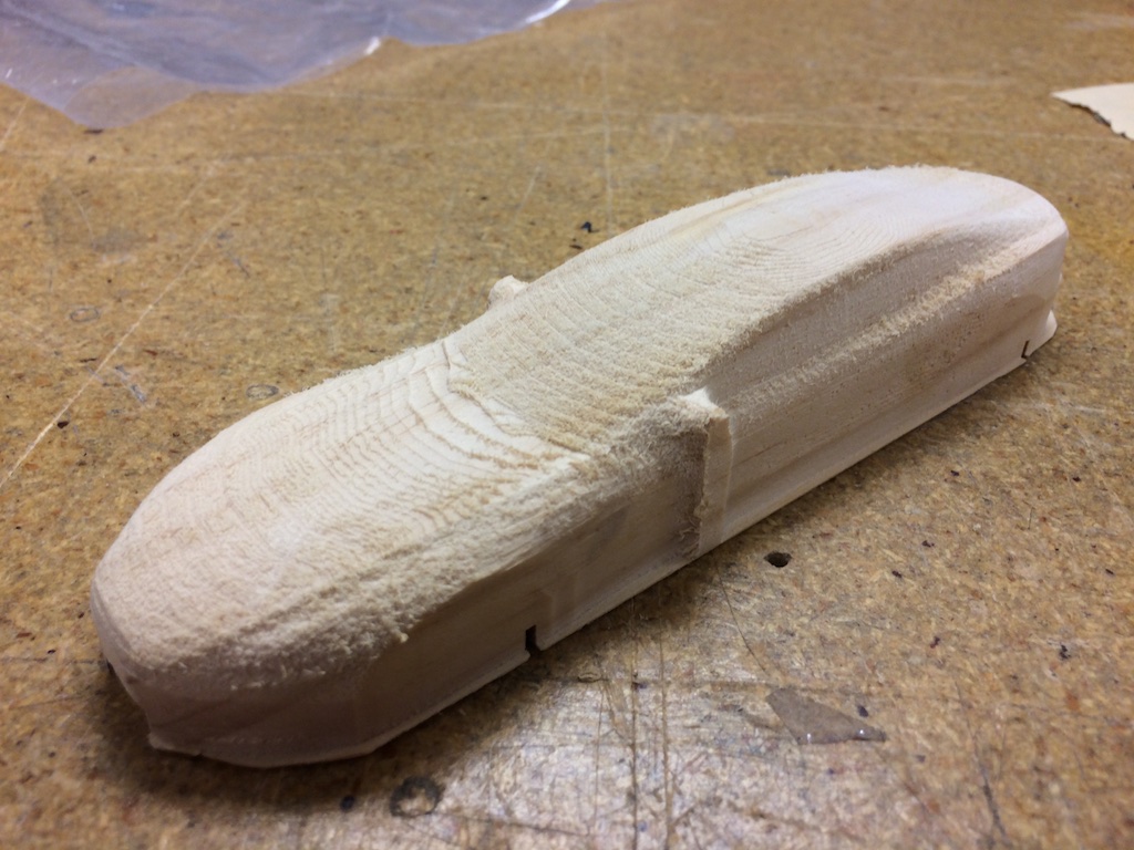
Carefully using a square-end X-acto blade, I carved out the space under the mirrors, rounded the nose, and cut out a little of the rear bumper. That and a hell of a lot of sanding gave me this:
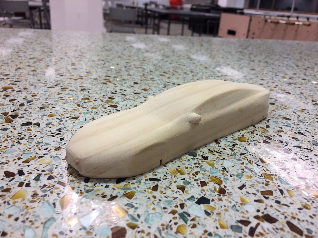
I was actually super surprised at how much it already looked like a Model S. You’ll note that the axle holes aren’t in the right spots. I spent a lot of time trying to get this to line up in last year’s car, but this year I opted to just use a sweet axle hole driller tool.
Next up was paint. First step, about five layers of acrylic Krylon spray paint:
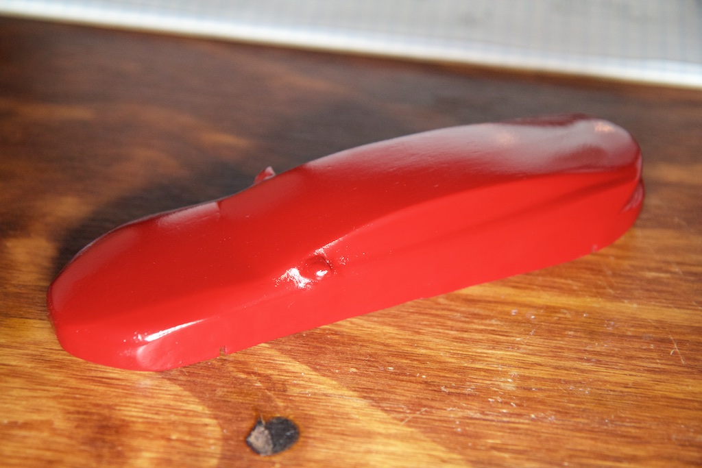
I forgot to buy primer, so I needed a lot of coats.
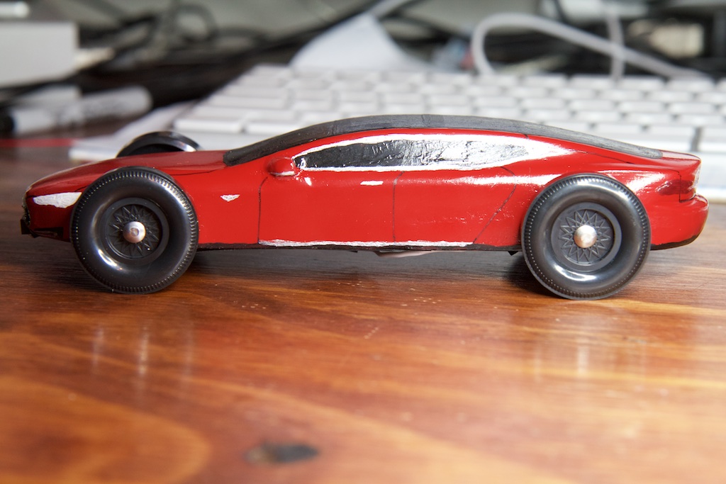
Then it was time to add some details. I bought a few colors of acrylic paint from a local art store and set to work:
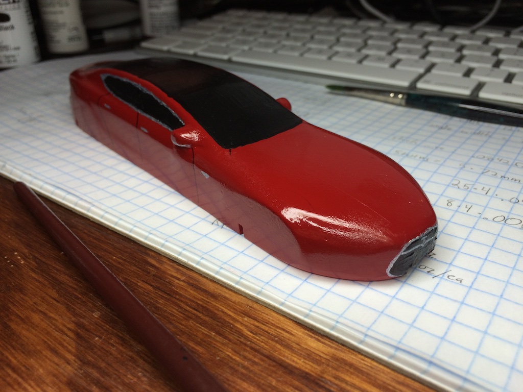
And done!
I used glossy black paint for the windows, and matte black to add the sunroof cross-beams. The frunk/trunk/door seams were drawn carefully with ultra fine point sharpie. I messed up at one point and had to sand the sharpie off and carefully mask and repaint. It’s still a little visible, but not too bad.
Next up, it was time to add the electronics.
Finishing touches
In order for my car to be mobile, I needed some batteries.
I found a big box of of Fullriver 661723HS25C batteries which are small, have a capacity of 160mAh, and are rated for 40C discharge (6.4A) for under 5 seconds of operation. They also didn’t have any protection circuitry on them, but I figured that if my car burst into flames halfway down the track, it would totally be worth it.
I had absolutely no plan to build a charger into my car at any point, so I manually charged a few with a power supply:
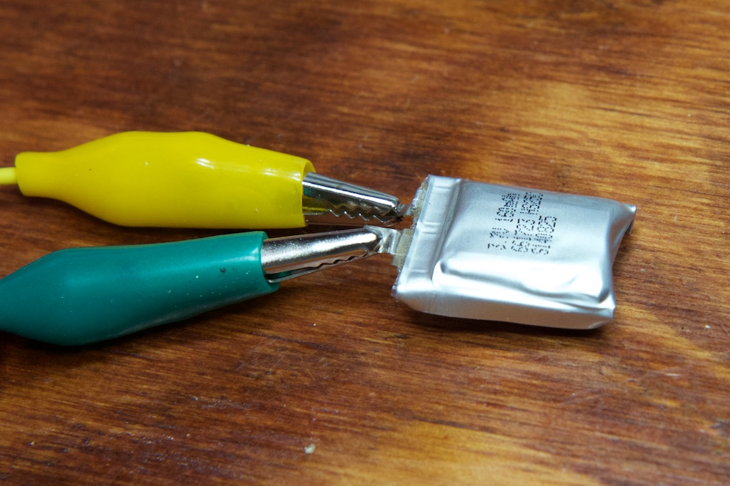
Charging slows down as batteries approach 4.2V, so I impatiently stopped them at about 4V. Next up, soldering them together:
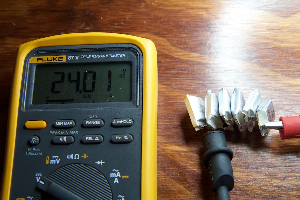
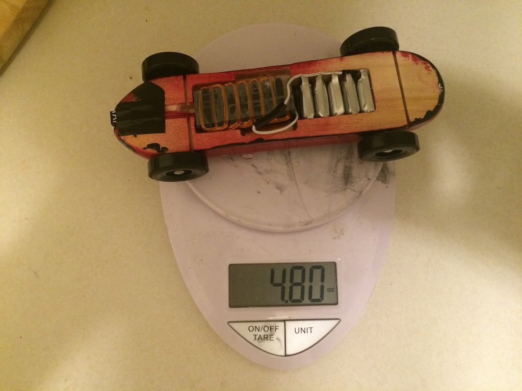
I originally planned to use six cells, but I had a bit of trouble getting all six to fit into the cutout I made in the car. Also, I had reworked a 100uF 25V electrolytic bulk cap to the power rails of my circuit (not pictured), and I was a little nervous about taking it within a volt of its rated limit. Five cells brought me down to 20V.
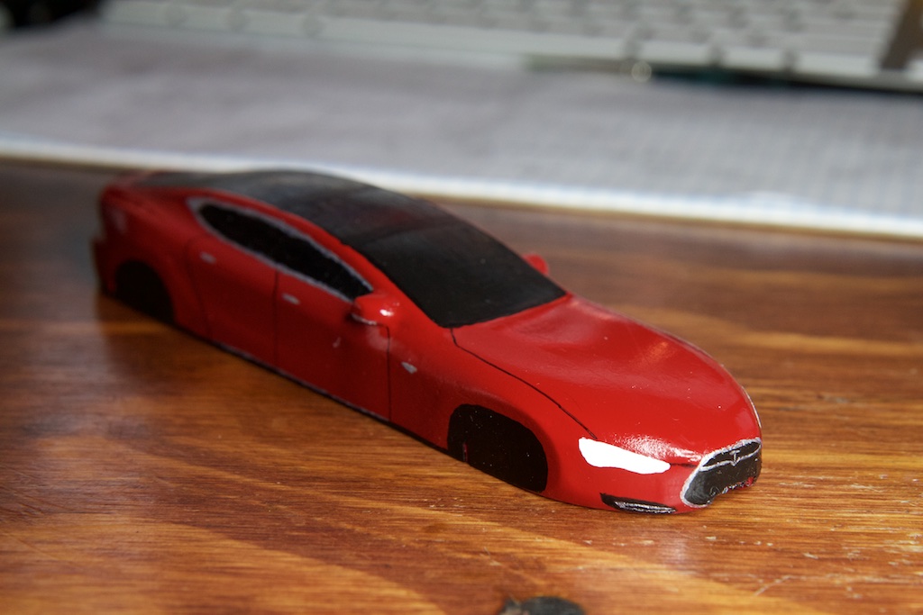
Then after nervously drilling and adding the wheels and electronics:
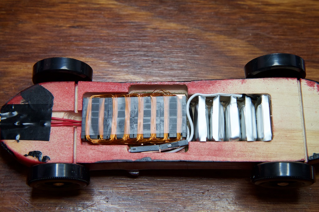
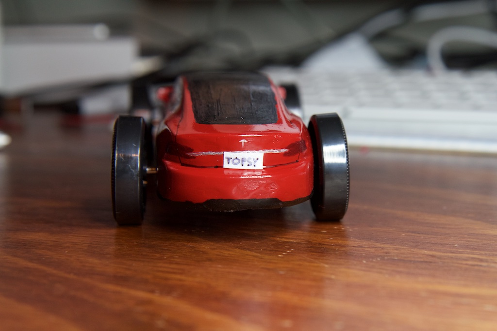
The license plate was made from actual retro-reflective tape.
The best part is that I came in under the 5oz limit!
I’m curious as to whether your firmware could’ve been improved further by refactoring the interrupt. Because interrupts must not change the state of the chip, the routine begins by pushing every register it uses onto the stack, and ends by popping them back off. The compiler is pretty bad at reducing number of registers used, so complex interrupts may have an overhead of about 30 cycles(15 registers, pushed and popped), about 2us at 16MHz, per interrupt.
This could be improved by reducing the complexity of the ISR, programming it in assembly, or by abandoning the interrupt and refactoring the timing-critical code into the main loop.
I’m not sure what your code looked like at this point, or what kind of timing requirements you had to meet at your fastest frequency, but I imagine that it could be possible.
Oh yeah, I’m sure I could have done a lot to make it faster. I’ll upload the code and design files tonight if you’re interested. I’ve only done assembly on the 8051, and I didn’t have enough time in this project to figure all of that out for the AVR, so I opted for more coils/slower frequency. Based on the measurements I took, I’d need to get my switching down to something like 5us per interrupt if I wanted to make it work with the smaller coils.
Neat project!
Your best bet on AVR is to just unroll the switching (you only have 6 steps — explicit code is way smaller than accessing data) and don’t even bother with interrupts. You can use a timer to set the overflow flag or similar, but you can just spin on that flag and clear it from software (write back the value you read) rather than even bothering with jumping to the vector, setitng up the stack, etc.
That being said, I do software PWM very similar to yours at much higher speeds with interrupts, but written in assembly, and with some tricky tricks like using “ijmp” as the interrupt vector. Doing that from C would be particularly fun. Last I experimented with naked interrupts on AVR, GCC would like to emit random moves to unused registers at times, making it very difficult to manage your own stack unless you just inline-assembly the whole thing. You can, however, reserve registers for this purpose, which is nice.
Nice job. I enjoyed reading it. You should test the motor again with the aluminum piece but use a piece of wood or plastic to give you a bigger gap between the motor and aluminum. Then you can see how much the bigger gap affected things.
Great job, and I’ll bet the winning car didn’t pass emissions!
>The strange thing is that it only ever used 17% of the processor and if I started another instance at the same time, it would take another 17%.
100/6 = 16.6667
It was a single threaded task, so it could only use one core.
Pingback: Bookmarks for October 13th | Chris's Digital Detritus
Pingback: TECNOLOGÍA » Lorentz forces and cheating at the Pinewood Derby
It kills me that you have to drop your voltage from 20V to 10V! Use a hardware timer (if available) to generate a 100 kHz PWM (if you can) to wave-shape the current and you wont need to! Your ultra-small inductance is working against you here.
DRV8313 is my favorite motor driver.
–Matt
I’m actually already using the hardware timer, but it’s a pretty complicated waveform to generate entirely with hardware timers (three phases and all that), so I ended up just increasing the number of turns.
Pingback: Ultrasonic parking sensor | ch00ftech Industries
Pingback: Lorentz forces and losing the Pinewood Derby | ch00ftech Industries
Pingback: Animated EVSE | ch00ftech Industries
Good web site you’ve got here.. It’s hard to find good quality writing like yours these days.
I seriously appreciate people like you! Take care!!
Pingback: Ultrasonic parking sensor • Tech Projects
44fy57
t8dolk
ifqoj4
a171f2
y9w73v
c4vw64
nnyqzk
5d1yso
wnhtgu
c1wzl2
k6uxvq
d2n01s
9ux7ci
jbj0lk
0xptw1
8or2rh
fcak3w
73sbbq
ium1wn
6zo2oo
9x7g9b