Everything I Know Is Wrong
So at this point in the project, I was pretty satisfied with my success. I now had a camera that could print out pretty decent pictures in under 30 seconds, and for my first ever time using ARM, I was moderately impressed.
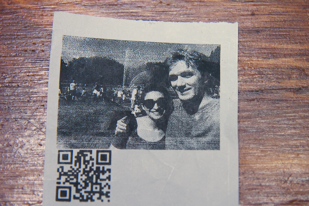
I was taking some more test images with some friends while walking through Pike Place Market when thy started asking me some questions about how the printer worked and if there was anything I could do to reduce the very apparent vertical black bars that showed up on the images. Up to this point, I was pretty certain that they were just an artifact of the low-quality thermal printer, but their questions got me thinking, so I ran a few tests when I got home.
Improving the printer
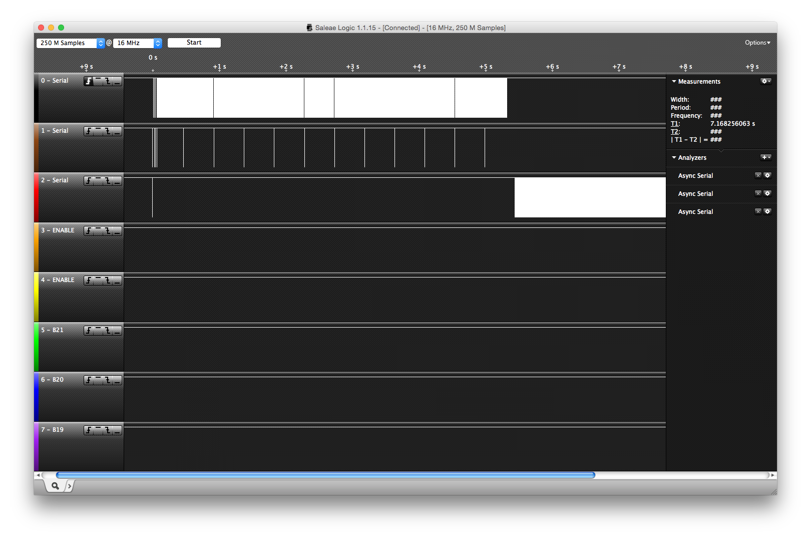
The printer accepts data at 19200 baud, so I’ve been pumping data to it at that rate. Without giving it any thought really, I had assumed that the printer just printed what it got as it got it and could keep up with that data rate. I mean, it makes sense right? The images took about 20 seconds to print. They were 640 pixels long, and at 480 bits per row (380 pixels plus start and stop bits), you’d expect it to print in about 16 seconds or so.
I did remember thinking that my new images didn’t look quite as good as the first image I printed out with the Arduino code:
Looking back through the Arduino library, I found this:
// Because there's no flow control between the printer and Arduino,
// special care must be taken to avoid overrunning the printer's buffer.
// Serial output is throttled based on serial speed as well as an estimate
// of the device's print and feed rates (relatively slow, being bound to
// moving parts and physical reality). After an operation is issued to
// the printer (e.g. bitmap print), a timeout is set before which any
// other printer operations will be suspended. This is generally more
// efficient than using delay() in that it allows the parent code to
// continue with other duties (e.g. receiving or decoding an image)
// while the printer physically completes the task.
Whoooops.
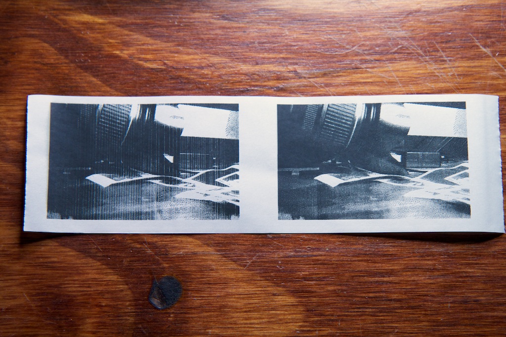
I quickly modified my code to add a short delay between each byte transmitted, and the results were obvious.
Not only does the image on the right not have any vertical bars, but the entire thing is generally lighter. I guess while it’s rushing to keep up with the incoming data, the printer tends to overheat a bit and muddy up some of the darker parts of the images. Now with that solved, my gamma correction is actually reducing image quality by reducing the contrast of the image.
It’s a really good thing I spent so much time figuring out how to do that.
The printer even sounds better now printing with a gentle buzz instead of a stuttering that I heard before. With my images looking about 200% better, I wanted to see if I could gather up another 20-30%.
PLL
If you look carefully at the right image above, you’ll notice that there’s a line about 1/5 of the way from the left side where the image seems to change brightness. I realized that while reducing the bandwidth going to the printer improves image quality, maintaining that quality across the entire image requires transmitting at a very fixed rate. Small changes in rate cause slight but very noticeable changes in image brightness.
Up to this point, I was using a software timer (just a delay loop really) which was really inconsistent between the three segments that I had split the image into. To get more consistent results, I would have to utilize a hardware timer.
I was already using one timer to keep the indicator LED blinking at a steady rate while the camera is doing more important things, so it was a matter of configuring another one. My initial settings should have sent data with about a 780
![]()
s delay between bytes, which I determined by experiment to be a good trade off between quality and speed.
But my data was going too fast. I hardly got any delay at all. This reminded me of a problem I had before with the LED. It too blinked faster than it should have, but I really didn’t think too much of it at the time and just guessed a value that made it blink at an appropriate-ish speed.
With a more critical application at hand, it was time to attack this bug head on. I started by doing the obvious things like check that my 8MHz crystal was actually running at 8MHz and making sure that I didn’t have any prescalers or anything set. The weirdest part was that everything seemed to run just about 15-20% faster than it should, but never twice as fast or (more realistically) slower.
I then started reading up on clocks. The clock system of an ARM processor is much more complicated than an AVR. There’s a huge section of system_stm32f10x.c that is used to configure the clock and PLL.
The default settings for the STM32F105 “connectivity line” device are configured for an external 25MHz crystal. The comments for the file say this:
HSE_VALUE is a constant defined in stm32f1xx.h file (default value 8 MHz or 25 MHz, depedning on the product used), user has to ensure that HSE_VALUE is same as the real frequency of the crystal used. Otherwise, this function may have wrong result.
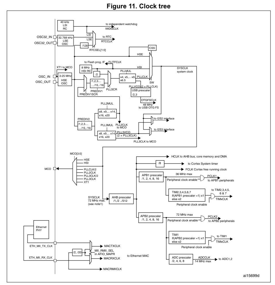
So I changed the value of HSE_VALUE inside stm32f10x.h from 25000000 to 8000000, and up to this point, I was plenty happy with that. I had a suspicion that the clock settings were responsible though since my timer was running at such a strange interval. I eventually dug up this diagram:
out of RM008 from ST. This indicates all the different ways that external (or internal) clock sources can be routed to different parts of the processor. I wanted to run my processor at 72MHz off an 8MHz oscillator which requires use of a PLL or “Phase Locked Loop” which is able to multiply an incoming clock to make it faster. This is exactly the setup I had on the STM32F407 Discovery board.
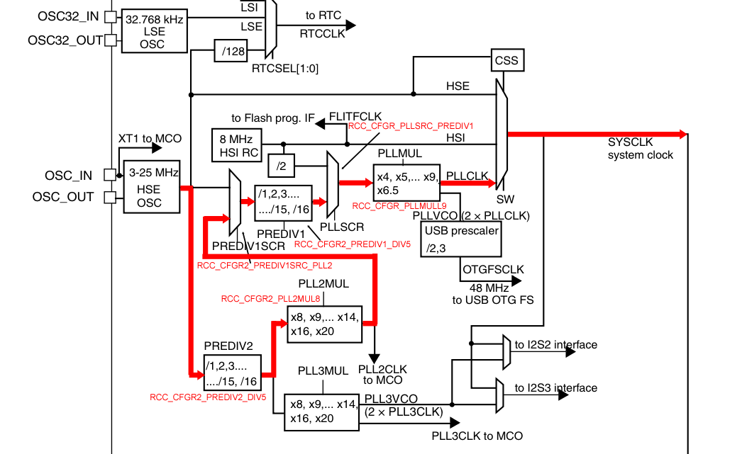
Since I didn’t remember configuring any of this, I figured that it must have something to do with the problem I was having. Sure enough, inside the function SetSysClockTo72() in system_stm32f10x.c, I saw this:
RCC->CFGR2 |= (uint32_t)(RCC_CFGR2_PREDIV2_DIV5 | RCC_CFGR2_PLL2MUL8 |RCC_CFGR2_PREDIV1SRC_PLL2 | RCC_CFGR2_PREDIV1_DIV5);
and then later
RCC->CFGR |= (uint32_t)(RCC_CFGR_PLLXTPRE_PREDIV1 | RCC_CFGR_PLLSRC_PREDIV1 | RCC_CFGR_PLLMULL9);
To the best of my understanding, this is what was happening:
To summarize, This set up takes the High Speed External clock (HSE), divides by 5, multiplies by 8, divides by 5 again and then multiplies by 9 to get the processor clock.
If I had a 25MHz external clock, this configuration would give me (25/5 = 5; 5*8 = 40; 40/5 = 8; 8*9 = ) 72MHz. As it was with an 8MHz clock, I was getting some weird multiple of 72MHz. After discovering this issue, I was a little upset that the ST library had all this great advice about configuring for an 8MHz clock, but left this vital tidbit out.
To get my clock working, I switched around a few things so now I was dividing the input by 2 and multiplying by 10. This gave me the same 40MHz that I had in the previous setup, so I left everything else the same. My final configuration looked like this:
RCC->CFGR2 &= (uint32_t)~(RCC_CFGR2_PREDIV2 | RCC_CFGR2_PLL2MUL | RCC_CFGR2_PREDIV1 | RCC_CFGR2_PREDIV1SRC);
RCC->CFGR2 |= (uint32_t)(RCC_CFGR2_PREDIV2_DIV2 | RCC_CFGR2_PLL2MUL10 | RCC_CFGR2_PREDIV1SRC_PLL2 | RCC_CFGR2_PREDIV1_DIV5);
And later:
RCC->CFGR &= (uint32_t)~(RCC_CFGR_PLLXTPRE | RCC_CFGR_PLLSRC | RCC_CFGR_PLLMULL);
RCC->CFGR |= (uint32_t)(RCC_CFGR_PLLXTPRE_PREDIV1 | RCC_CFGR_PLLSRC_PREDIV1 | RCC_CFGR_PLLMULL9);
Not only did this fix my timer problem, but it also drastically improved the performance of my processor! Remember that 1 second processing delay I couldn’t get rid of?
Gone!
This actually caused a problem initially because my software delay timers (which I was using for printer configuration) were now much faster, and since my JPEG decompression algorithm ran much faster, my processor was finishing blocks before the DMA transfer of the next block was finished. I had to add some code to actually slow it down.
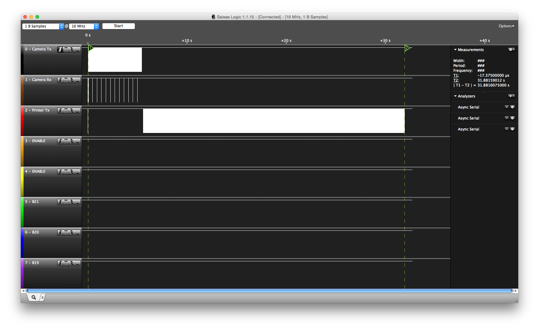
In fact, the entire process from shutter release to paper tear adds up to just over 30 seconds:
Gee, better picture quality and improved speed. And these were two problems I could have fixed from the start. Go figure.
JPEG Problems
At some point during this process, I managed to introduce a new bug that gave me about a 10% probability of printing out garbage or repeating the previous picture. This meant that something was wrong with PicoJPEG. If PicoJPEG failed, my code would skip right to the printing step where it would either reprint the previous image that was still in memory or print garbage if this was the first picture since power on.
I didn’t think much of it while I was in the midst of changing things, and I honestly couldn’t remember if I had always had that bug. The camera has never been super reliable, so maybe it just spits out garbage like that sometimes? Either way, now that I had some room to breathe it was time to drill down. Before moving on, I’d like to point out that I was up until 3AM literally every night this past week trying to fix this bug and had a pretty relaxing weekend as a result.
Part of the problem with debugging anything involving JPEG is that the format is more or less designed to recover from small data errors. When a bug injects some nonsense into a JPEG stream, there’s a chance that you won’t notice anything different. Furthermore, every picture this camera takes is very slightly different, so if one picture causes an error, the next one might have its bits organized in such a way that the problem doesn’t occur. This was a total pain to deal with.
DMA bugs
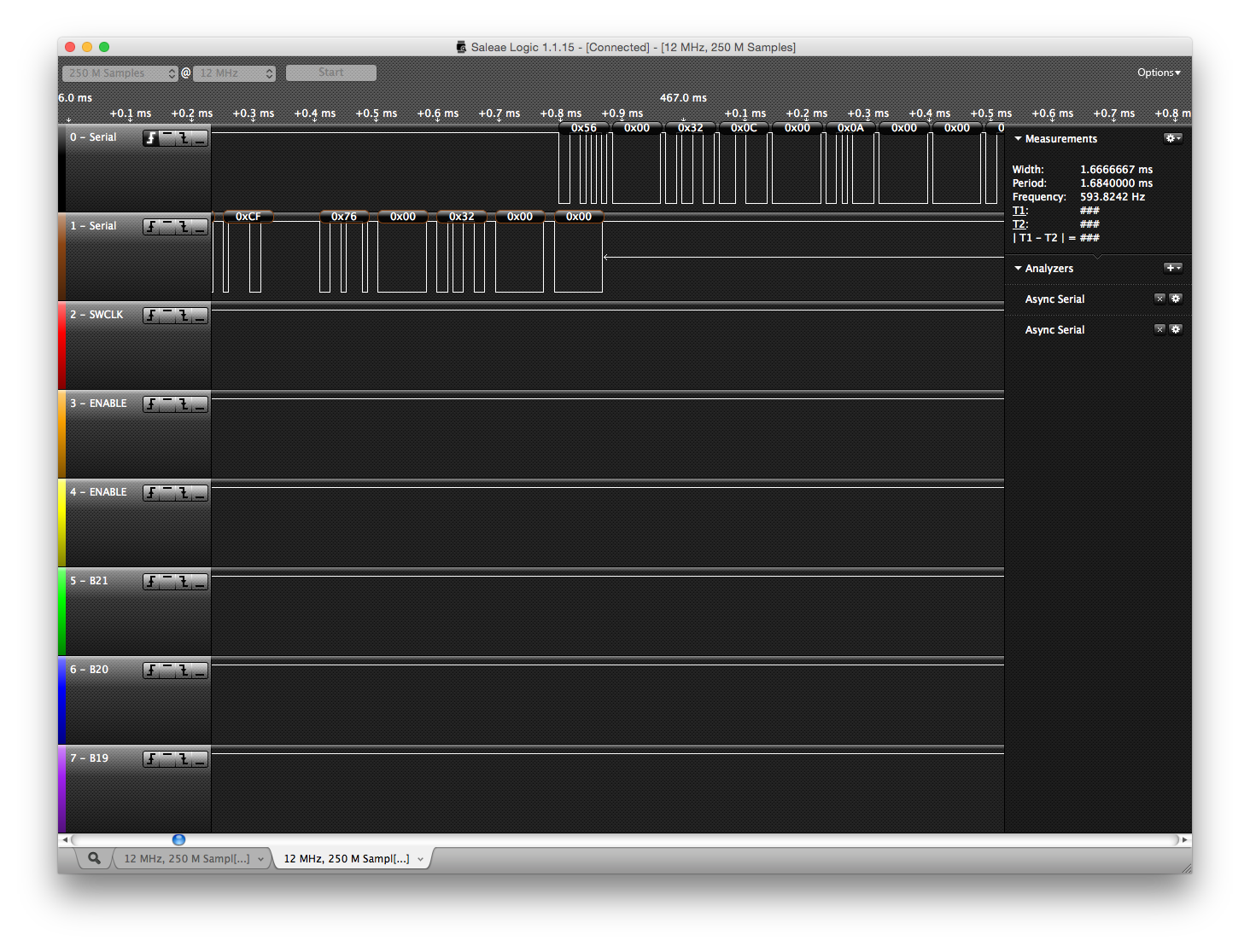
First the easy bug. I noticed something a little troubling after setting up my DMA to copy the image data from the camera module. Sometimes, the DMA would finish early and my processor would start sending commands for receiving the next portion of the image before the previous portion was finished. Here you can see my processor sending 0x56 out before it received 0x00:
At first, I assumed that this was some kind of timing problem where I was setting up the DMA too fast and causing it to grab its first value before the beginning of the incoming stream. This extra value at the beginning would cause it to finish one byte too soon.
Adding a few delays made it clear that this wasn’t the case, so I dug into the DMA configuration settings and learned about this command:
USART_DMACmd(USART2,USART_DMAReq_Rx,ENABLE);
So long as this command is enabled, the DMA will grab a value out of the USART RX register as soon as it arrives. I was right that it was grabbing the first value too soon, but it had nothing to do with delays. I wasn’t disabling this command between DMA transfers, so the DMA was sure to grab the last thing transmitted through the USART as soon as it was reenabled and treat it as the first byte of the next transfer. I added a DISABLE command to my waitForDMAComplete() routine to guarantee that it gets shut off as soon as the DMA is no longer active.
PicoJPEG
With all of this in place, my bug was fixed!
Or wait…hold on, it just happened again.
Nope. It’s not fixed. Another frustrating aspect of this bug was that there was no way to 100% verify that it was gone. The camera could go for 20 exposures straight with no problems and then bug out on 21. It was only after a few more nights of spinning in circles that I decided to get a little more serious about my debugging methods.
I wrote a few different versions of my firmware. One allowed me to once again pre-program JPEG images in memory and simply decode and print them out.
The other tested my code by detecting when the JPEG decoder failed and holding the red LED on when this happened. When the decoder succeeded, it skipped printing and just took another picture automatically. It usually only took a few minutes to reproduce the bug with this firmware in place.
My first task was to verify that the camera was getting the correct data. Using GDB, I was able to download the entirety of both DMA buffers to a log file and compare them to what I captured going into the device with my Saleae. The DMA buffers aren’t big enough to store an entire image, but since PicoJPEG crashed while this was still in memory, there was a good chance of there being an issue with that portion of the data.
A thorough analysis with some Python CSV file manipulation indicated that there was no difference besides the header and footer bytes which my code was designed to ignore:
So I had to go deeper. PicoJPEG was dropping out and there had to be a reason why.
First, I wrote the code mentioned above that let me load up a JPEG into flash and decode and print it.
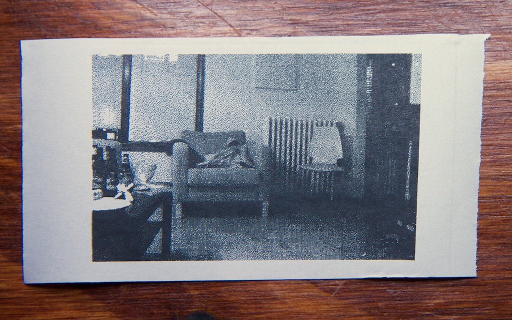
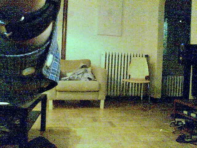
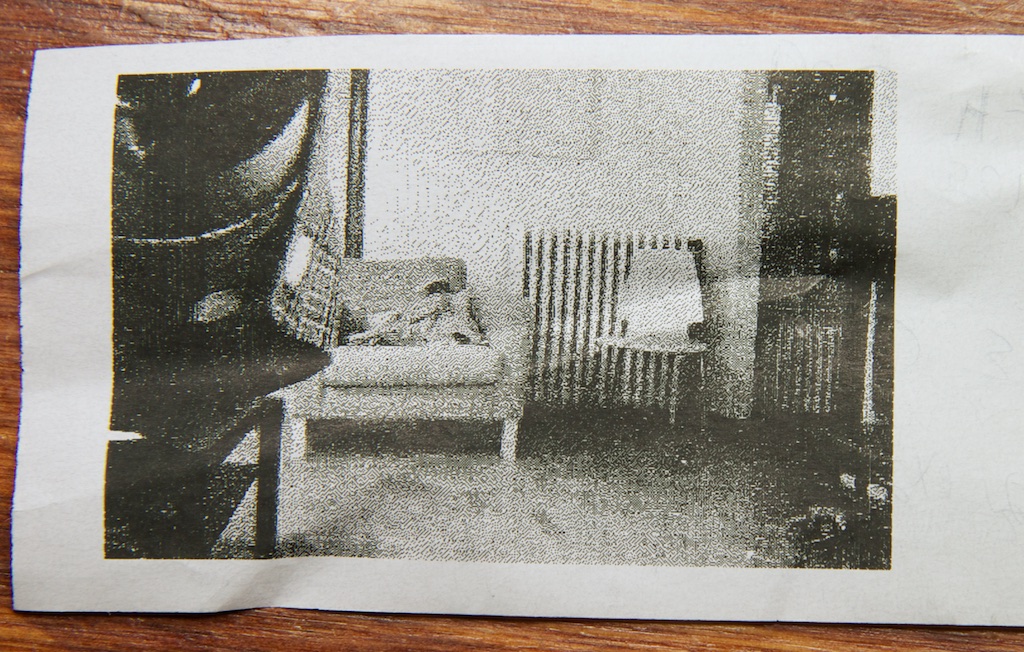
As a side-note, this was the first time I had actually ever taken an image with the camera module that ended up on a computer screen, and I was a little shocked at the image quality:
Maybe it’s that we’re preconditioned to know what a terrible JPEG image looks like or that the dithering algorithm covers up JPEG artifacts and noise, but I think the printed version actually looks a little better than the original. Though with that kind of quality, that’s not saying much.
With my code now able to reliably decode and print images stored in flash, it was just a matter of getting a trace of a JPEG stream that caused the bug. I modified my second script so that it would lock up after it caught an error and then wait for a button press before asking the camera module to dump its entire memory in one go. This made it easy to capture using my logic analyzer.
Try as it might, my camera could not decode this image. After a few days of trial and error, I finally had a method for reproducing my bug! Now it was only a matter of time before I figured out what was causing it.
If PicoJPEG discovers a problem during the JPEG decoding process, it will exit with a status message. The error I got most commonly was “PJPG_BAD_RESTART_MARKER”. This warranted a little more research into how JPEG works.
JPEG files are decoded linearly (though there are some methods for splitting them up and decoding in parallel) and different sections can have varying length depending on image content. To deal with this, the format has a series of markers that are always the byte 0xFF followed by a marker byte. Wikipedia has a good description of them here.
Reset markers are characterized by 0xFF followed by 0xD_ where “_” is increasing values from 0-7 and starting back at 0 again. They’re used to help a decoder recover from an error in the incoming data. As JPEG images are decoded, information about previous pixels is used to decode later pixels. If there’s an error in one part of the image, this could cascade and ruin the rest of the picture. To get around this, reset markers tell the decoder to reset all of its stored information and start over again.
I’m not too certain if locating these markers can be more deterministic, but PicoJPEG is written to search some portion of the image data for the next reset marker.
This code looks for 0xFF followed by 0xD_ and if anything else is found, it returns PJPG_BAD_RESTART_MARKER.
But what if the image actually has the value 0xFF (255) in it somewhere? According to Wikipedia, when the number 0xFF is present and it isn’t a marker, it’s supposed to be followed by 0x00 to indicate that it’s a regular image value.
I don’t know if my images are strange or what, but while PicoJPEG was written to account for these “escape bytes”, the portion of code designed to look for reset markers was not. For some images, it would randomly come across a 0xFF value while looking for a reset marker and then exit out of the loop with an error.
Adding a small change to fix that and… BOOM!
I shot an email to the code’s author describing what I found, and I’m currently working with him to update the code. YAY I HELPED! I’m still not certain that this is a real bug though because both of these images decompressed fine using the version of PicoJPEG compiled for Windows. Maybe it’s something weird with how I was using it.
While I was super excited to have fixed this bug, you might have deduced from the scribbles faintly visible from the back of that image that I wasn’t done yet.
PBUF
Despite finding two smoking guns, I still had a problem. My camera was still bugging out at almost the same rate as before. Since I had established that my DMA buffers were getting the exact data that the camera was sending, the problem couldn’t be with the DMA. Furthermore, the confusing addition and subtraction required to get the two buffers to overlap and handoff smoothly all checked out when I poured over them again.
Finally, I decided to take a look at the data entering “pbuf” which is PicoJPEG’s 250-something byte buffer that it uses for decoding. This proved a little difficult. I think something is wrong with my debugger setup because grabbing the values of certain variables or breaking in certain functions causes GDB to completely lock up my terminal. To get a look at pbuf, I resorted to spitting it out through the printer UART and capturing it with my logic analyzer. Since the printer had no idea what to do with this random stream of bytes, it gave me some pretty funny results:
Because my DMAs weren’t smart enough to ignore the header and footer data coming over the serial stream from the camera, I took my routine that starts up the camera’s UART stream and changed it so that it would also return the future memory address of the first piece of real image data from the DMA.
This feature was added a little late in the game, and apparently I forgot to update every instance of it being called.
Immediately after the picture is taken, I have a single call to start the DMA so that it has a head start while the processor is getting prepared for the incoming data. Since this routine originally didn’t have a return value, my code wasn’t originally written to accept said return value. Instead, I was using the default start address which was the beginning of my DMA buffer and included the five bytes of header info.
I have no idea why this thing was able to work at all, but the entire time I was using the DMA, I was passing five bytes of junk to PicoJPEG at the beginning of every image stream. Apparently JPEGs are resilient enough to recover from that a decent percentage of the time.
Once I fixed that bug, I grabbed a drink and sat there watching the camera loop through JPEGs just waiting for the damn light to turn red. After about 20 minutes of this, I figured I was out of the hole and had everything working.
WOOOOOOOOP! My week of hell was over.
Other software notes and power management
While it would be really great to add in a gas gauge feature and some sweet battery management, I’m a little close to my Christmas deadline. I decided to do the bare minimum right now, but I’ll be sure to include the rest of everything when I build my second prototype after the holidays.
At the moment, my code monitors for the presence of the battery (switched on) and charger (plugged in). The design of my circuit prevents anything from happening if the user tries to take a picture while charging (the printer is unpowered in this state), but I was concerned that it would be confusing to the user when the LED indicates that a photo is printing while nothing is coming out.
To improve this interaction, I use the indicator LED to remind the user that the charger is plugged in and disable picture taking. This is all performed inside the loop that waits for the press of the shutter release button. I also monitor the “CHRG” pin of the battery charger and light up the LED red while the battery is charging and green when charging is completed.
I haven’t even tested the battery voltage measurement circuit at this point, but considering that the battery has a built in protection circuit and is big enough that I’ve never managed to kill it during testing, I’m not too concerned for an early prototype. I’ll just remind my sister to keep it well charged.
I didn’t put any effort really into optimizing this system to make the most out of its battery. The reality is that the printer currents are so huge compared to everything else that I’m not likely to gain much back by cleaning up.
When switched off, I measured 12
![]()
A being drawn from the battery. This is the current flowing backwards through the charger and is more or less in line with the 8
![]()
A prediction from the datasheet.
The “standby” current while the device is on and waiting for a shutter press is 80mA. Surprisingly, most of that is the 50mA from the camera module.
Finally, when printing a completely black image (thumb over the lens), the circuit averages just under 1.5A. I was expecting something like 3A, but my early measurements may have been just peak currents, and the printer could need less power now that I’m sending data to it slower.
Anyway, at 30 seconds a pop, this thing should be able to print well over two hundred pictures before it needs a recharge.
Battery troubles
Of course, in the true ch00ftech spirit, nothing is ever easy. While I was working on this short snippet of battery code, I ran into a problem. Because my battery was already fully charged, I had no way of knowing if the charging indicator LED worked. Rather than printing a bunch of worthless pictures, I decided to just connect the battery to a load to wear it down a bit.
The nearest thing I had at hand was a solenoid which drew around 300mA when connected to the battery. Now, I don’t know exactly what happened, but returning to the solenoid and battery after a 10 minute break, I measured the battery at 0V. Disconnecting the solenoid gave me a 2.5V no-load output, but it quickly dropped to zero with any kind of load attached. Connecting it to a charger raised the terminals to 8.4V immediately, and disconnecting dropped them down to 2.5V again.
Here I am three days before flying home for the holidays, and the big gift that I spent three months developing was busted. I only ever had one battery, and these things take like a week to ship because they’re assembled by hand.
Ten minutes is not a lot of time. If the battery really discharged that quickly, there would be a lovely smoldering hole in my desk, so I wasn’t convinced that the battery was really hosed. As I mentioned before, the battery has a protection IC, so if there was a problem, that’s where it was.
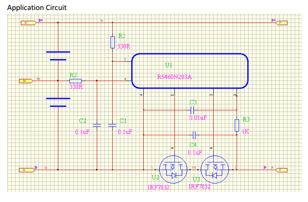
Looking back at the datasheet, my speculation about the battery protection and wear leveling IC was correct:
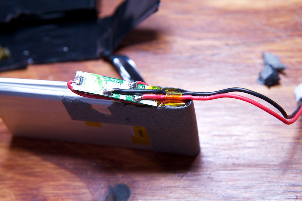
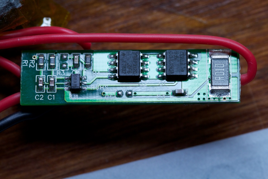
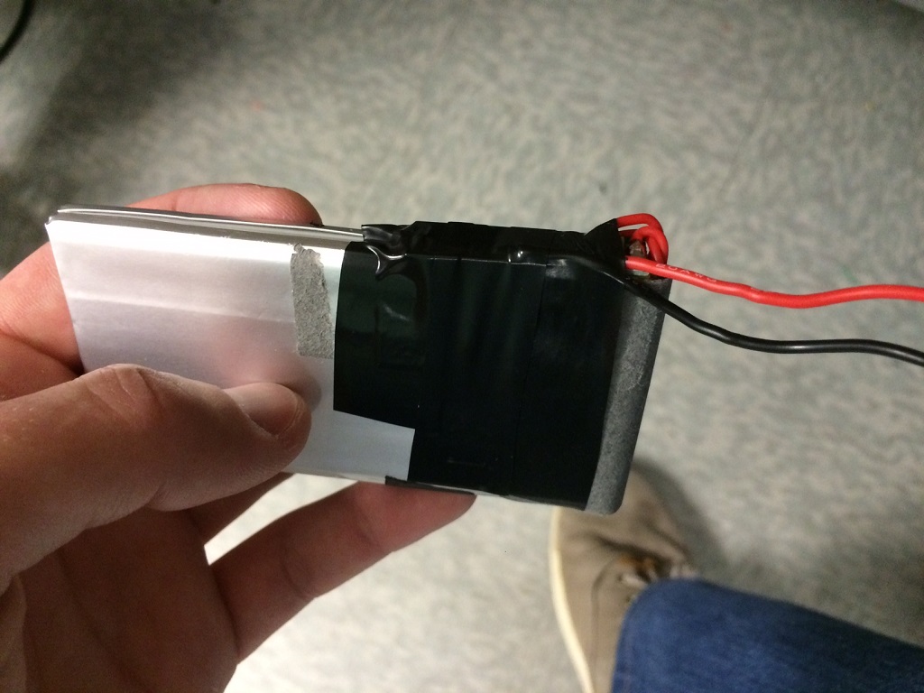
I opened the battery extremely carefully using a razor blade and found two lithium polymer packs and a protection PCB:
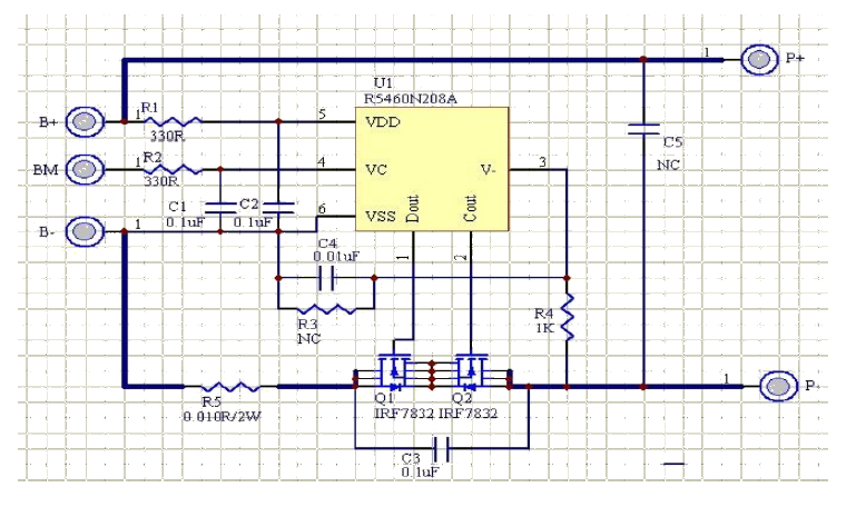
This PCB had a slightly different layout than what I saw in the datasheet (for example, that huge 0.01 ohm resistor isn’t shown anywhere in the datasheet). All-battery.com also sells the protection circuit separately. The datasheet for that PCB is more accurate:
Both schematics agree that they’re using the R5460 from Ricoh.
When I started this endeavor, I figured that the battery shorted out when I connected it to the solenoid and was stuck in its overcurrent protection mode. Usually you can recover from this by simply disconnecting the load and connecting the battery to a charger. When this didn’t work, I was hoping that I could force it out of this mode by poking at it a bit.
I tried everything. Disconnecting the battery terminals to cut power to the IC, forcing the protection FETs to turn on hoping that they’d “stick”, forcing the “V-” line down hoping that it’d recognize the presence of the charger and un-stick, etc.
After an hour or so of this, I finally gave up and determined that the “damn thing was broke”. My best theory is that the back-EMF from the inductor in the solenoid produced a large voltage that fried the protection IC. No amount of poking or prodding would bring it back to life.
Fortunately, while All-battery takes 8 days to make these batteries, they do sell the protection PCBs immediately. ![]() 55 overnight shipping later and I had a few backup PCBs in my hands.
55 overnight shipping later and I had a few backup PCBs in my hands.
Swapped out the PCB and once again everything was great.
Good as new!
Table of Contents
- Background
- Component Selection
- Electrical Design
- Mechanical Design
- Software
- Everything I Know is Wrong
- Marketing and Conclusion




Pingback: Towards More Interesting Instant Cameras | Hackaday
Pingback: Towards More Interesting Instant Cameras - Tech key | Techzone | Tech data
Pingback: Towards More Interesting Instant Cameras | Ad Pub
Pingback: Towards More Interesting Instant Cameras | Hack The Planet
Pingback: Towards More Interesting Instant Cameras | 0-HACK
Thoughts about heading toward a KS project:
1. Separate the battery/charger from the camera/printer: Support attached and/or detached/cabled power, with standard LiPO standard and the option of a pack with replaceable/rechargeable NiMH cells (dirt cheap). Then, also offer the camera without a battery pack (DIY power is relatively easy if the interface is simple).
2. Personally, I’d want a clear case with all the internals visible, using standoffs and 3D-printed brackets where needed. Hopefully, this would also be the simplest/cheapest case.
3. Kit the custom parts and include a simple “no-solder” BOM for the rest. This permits a “partial gift” for the makers among us. And I certainly don’t mind giving Adafruit some business, especially if a small discount can be negotiated for this project’s BOM.
I think the above can provide a wider range of KS options and price levels with (hopefully) relatively little change to the core device.
Pingback: PrintSnap Wants to Bring Back the Instant Picture Using Dirt Cheap Receipt Paper
Hey there, I think this might interest you: http://www.sciencedaily.com/releases/2014/10/141022143628.htm
Yep, I’m well aware of that problem. I wash my hands compulsively anyway, and I’m sure someone will come around with a BPA-free option soon in response to public outcry. The same thing happened with Nalgene and leaded gasoline.
I want this! I want this soooo bad. Please sell me the first one!
Pingback: PrintSnap Wants to Bring Back the Instant Picture Using Dirt Cheap Receipt Paper - news from Allwebsolutions.net
When this becomes available, make sure it can be sent to Australia!!!!
Pingback: l’appareil photo instantanée le plus économique | news-apple
Hi Ch00f,
Your PA15 pin isn’t busted; the problem is that it is by default mapped as a JTAG debug pin and not to the GPIO block. In the device datasheet (the 100-page thing, NOT the 1000-page reference manual), there will be a “pin definitions” table near the front containing pin numbers for all the different package options, pin names (“PA15”), pin-types (“I/O”) and 5V-tolerance (“FT”), a “Main Function” column (this is the important part) and “Alternate Function” columns.
Note that for most GPIOs, the Main Function is GPIO, i.e. at power-on, PC12 is PC12, etc. However at power-on, PA15 is JTDI (jtag data in). This is necessary so that JTAG can start talking to a device when it boots. If you’re using SWD (and it seems you are) and want to make use of the PA15 pin, you need to disable the JTAG peripheral and its pin remapping.
Note that if you don’t want to be able to debug or maybe ever load code into the device again, you could also free up PA13 and PA14 which are the SWD pins.
Email me if you get stuck and I can send you the specific line of code you need; I just don’t have it here right now.
(I found this one out the hard way while playing with an stm32; I wasted a good 4 hours figuring it out)
THANK YOU
I figured it was something like that. I mentioned that part specifically hoping someone would figure it out for me.
Thanks for the tip!
Pingback: Prints for less than penny
Pingback: PrintSnap: A Home-Built Camera That Prints on Receipt Paper (and Almost for Free)
Pingback: The Quirky PrintSnap Instant Camera Let's You Create Instant Prints On The Cheap - DIY Photography
You are a silly man with silly ideas. As soon as I started the video I thought, “Why is he recreating the GameBoy Camera/Printer?” Your presentation was mockingly beautiful. It’s good to see your personal projects continue to be so whimsical.
What’s nice about the Cortex series is that some of the “peripherals” are standardized by ARM, so no matter the manufacturer, they’ll all behave the same. SysTick, FPU, NVIC, etc.
To enable the FPU, google “cortex m4 enable fpu” and you’ll find the following asm to do so (basically setting a couple bits to turn on the coprocessors in the coprocessor access control register):
; CPACR is located at address 0xE000ED88
LDR.W R0, =0xE000ED88
; Read CPACR
LDR R1, [R0]
; Set bits 20-23 to enable CP10 and CP11 coprocessors
ORR R1, R1, #(0xF << 20)
; Write back the modified value to the CPACR
STR R1, [R0]
I'm actually working on a project right now using a thermal print head, but rather than an all-in-one module like you have, I am using discrete components: a solenoid to push a kyocera print head onto the paper and a stepper motor to drive the paper through. I can print a 1450×672 px image in 3-5 seconds. In my case, going faster actually improves the quality of the print because the print head stays warm.
Pingback: PrintSnap: eine Sofortbildkamera, die Thermopapier statt PolaroidInstant-Film verwendet | Foto[gen]erell
I like this idea, the camera itself is sound for a version 1.0 project. To make it “sellable” you should consider a different housing altogether to make it look like an old school camera. Two ideas I thought are a TLR (like a Rollei) where the user looks down at a mirror to compose the image through a lens, while the camera is in a lens just below it, and the printer goes out the side. Another is a Brownie box camera style with an offset finder and the camera in a central front port. Either way something that looks like an old school film camera from a few feet away would be a winner.
Pingback: Una cámara DIY instantánea
Pingback: Una cámara DIY que hace fotografías instantáneas mas baratas que una Polaroid | Android 3G
Pingback: PrintSnap:用小票做相纸的黑白拍立得相机 | 趣火星
Pingback: PrintSnap Kamera Cetak Instan - Titikfokus
Pingback: Instant Camera Uses Receipt Rolls For Printing Paper - PSFK
Pingback: Instant Camera Uses Receipt Rolls For Printing Paper * The New World
Pingback: This instant camera will print images on a receipt paper roll - Berbit.net
This is fantastic! You basically made a spiritual successor to the King Jim Da Vinci DV55. I really want to see this becoming a real product and hope you go with Kickstarter on this project!
Pingback: This instant camera will print images on a receipt paper roll * The New World
Pingback: This instant camera will print images on a receipt paper roll | xoneta.com - majalah online gadget, komputer dan teknologi terbaru
please keep me posted on all news!
Pingback: PrintSnap, una cámara instantánea con la que imprimir fotografías en el papel de los tickets
Pingback: PrintSnap, una cámara instantánea con la que imprimir fotografías en el papel de los tickets | Fravala.com - Las noticias de tecnología a tu alcance.
Pingback: PrintSnap, una cámara instantánea con la que imprimir fotografías en el papel de los tickets - QuickIdeas
Pingback: PrintSnap, câmera instantânea para imprimir fotos em papel de tickets
Pingback: PrintSnap, una cámara instantánea con la que imprimir fotografías en el papel de los tickets • 25 noticias
Pingback: PrintSnap, a camera which prints the photo instantly | Minionvilla
please add me to your mailing list.
love it!!
i
Pingback: PrintSnap: an Instant Camera, which uses Receipt Paper instead of Polaroid/Instant Film |
I want this. If it’s become product please sell at JAPAN too.
I hope ship to Japan!
I’d like to buy it!
please send me all news about it.
l love it
ほしい!
これは楽しそう!
発売されたら買います 😀
Fantastic ! I love it !
Great! I want to buy one.
Great !!!!!! I want this.
Great!!
It must be goint to be a great tool.
I am really excited about it from now.
I want buy it!
it’s a fantastic invention Really hoping to the real product asap!!
Japan.Yokohama
great‼︎ please add me to your mailing list.
I love it !
Fantastic!
Please let me know your progress of the masterpiece.
soooo geate:)
i want this!!!
PrintSnap is very good.
I like it !
Please add me to your mailing list.
欲しいです!
I like this idea!
It’s fantastic!
Please add me to your mailing list
I remembered a pocket camera of Game Boy!
Wonderful.I wait for a followup!
The thing that is really cool. Commercialization sure if I want to carry one.
コレは面白い!!( ´ ▽ ` )ノ
I like it!
I WANT CAMERA!
Hi !
I like it !!!!
これは欲しい!
Please sell me the first one!
Very cool! Sell me as soon as possible!
販売したら購入検討したい、
興味があります、
Amazing….Please add me to your mailing list!!!!!
とても楽しそう!
booked
This is really amazing! I really want to have one! please add me in your mailing list.
I can’t wait for this on sale… 😀
cool
Good
I Want to buy this camera
Pls let me know any infos,
Pingback: PrintSnap – レシートの感熱紙にプリントできるインスタントカメラ | トイカメラ。【トイカメラとトイデジの情報】
Great!
I want it.
Pingback: PrintSnap is a Lo-Fi Polaroid that Uses Thermal Printing | Digital Trends
Pingback: PrintSnap instant camera concept uses receipt paper for low-cost solution - news from Allwebsolutions.net
Pingback: PrintSnap instant camera concept uses receipt paper for low-cost solution | TechnoTwitts | TechZone | Technology Updates | Gadgets Reviews
Pingback: PrintSnap instunt camera concep uses receipt pap'r fer loe-cost solushun zano mini drone | T'Redneck Revue
It is a great idea. This would be a great present for my 8 years old daughter who loves to take pictures. PLease make it at an acceptable price for normal people.
Thanks
Pingback: PrintSnap Instant Camera
This product concept is awesome!!
Plz add my name on your list!!
I’d love to buy!
Its fantastic! Let me know when is available!
Pingback: La “Polaroid” più economica di sempre, funziona con gli scontrini (foto)
this would be a hit on kickstarter, its totally geared towards the 20-30 something year old, new and upcoming product loving, crowd that kickstarter brings in. where are you based out of?
Hi ch00f!
We really like your “PrintSnap Instant Camera” project and want to cover it on EEWeb.com for our readers.
EEWeb.com is an online resource community site for Electrical Engineers and I’m sure that your project will be a great addition as an entry on our webpage.
Would it be ok, if we write an article about your project and include some pictures and other relevant materials?
We will give you credit for the project and link back to your site so our readers can learn more about you.
Hope to hear from you soon.
Regards,
Tin
Sure! Go for it. Send me a link when it’s up.
Hi! That’s good to hear. Thank you.
We will update you the moment the project is already live on our site.
I want this!
u got a great idea!
i want it!
I will buy this camera!!!
Please tell me as soon as you launch!
Pingback: Instant Camera, Instant Receipt Paper Pictures / Receipt Rolls Blog
I want this.. Hope you ship it in the Philippines
That is great use of thermal paper roll.haha~
It could be really nice if you can use your code to create something like an app for smartphone who can automatically dither the photo you take and send it to a bluetooth thermal printer !
Pingback: Actualidad: PolaPi es un fantástico homenaje a las Polaroid y está basada en una Raspberry Pi | Compu Vigilancia
Pingback: PolaPi es un fantástico homenaje a las Polaroid y está basada en una Raspberry Pi | Nuevo Titulo |
Pingback: PolaPi es un fantástico homenaje a las Polaroid y está basada en una Raspberry Pi | TecnologiaDigital
Pingback: PolaPi es un fantástico homenaje a las Polaroid y está basada en una Raspberry Pi | Ceo Bolivia
Pingback: PolaPi es un fantástico homenaje a las Polaroid y está basada en una Raspberry Pi - TodoMovil
Pingback: PolaPi es un fantástico homenaje a las Polaroid y está basada en una Raspberry Pi - InformeGeek
Pingback: PolaPi es un fantástico homenaje a las Polaroid y está basada en una Raspberry Pi
Pingback: PolaPi es un fantástico homenaje a las Polaroid y está basada en una Raspberry Pi - ChatNews
Pingback: PolaPi es un fantástico homenaje a las Polaroid y está basada en una Raspberry Pi - FM Centro
Pingback: PolaPi es un fantástico homenaje a las Polaroid y está basada en una Raspberry Pi - Point Fusion
Pingback: PolaPi es un fantástico homenaje a las Polaroid y está basada en una Raspberry Pi | Noticias: TecnoAR - Agencia Diseño Grafico & Web
Pingback: PolaPi es un fantástico homenaje a las Polaroid y está basada en una Raspberry Pi | Dellthus – Noticias
Omg..I love it … I hope it becomes available soon..
U rock!!!
me to 😉
Pingback: Electrolytic capacitors and preserving a family heirloom | ch00ftech Industries
how could i get one ? looks wonderful
Pingback: Las maravillas de Raspberry Pi! – Tara2
Pingback: Animated EVSE | ch00ftech Industries
I think is a great invention alright i never would have come up with that idea ist nice to see other beings like myself that are creative that think outside of the box that are not ordinarily “bookends fir i have made inventions too like a mammoth gunboat whitter folder pocket knife which you cant put in your pocker most of the components are made of wood the spring is made of pernabucco which us primarily made for the use of violin bows because of its incredible inert retention
Ability the only metal is the blade itself from a barbecue cutlery set that the handle
Rotted and I revamped the blade. Total length is approx a foot and a half Ebony Gabon is used for the stationary retainer and pivot pin I hope i did noi talk your ear off ps. Ive been meaning to contact case cutlery because they are ineed of engineers and a friend up the street also is creative in this field he is very adequate when it comes to tolerances he helped me with ideas in design just by his influence and knowledge.
buyc4nmd
Adriana want to play with you! Start Play: http://inx.lv/GkWu?h=232b90475fdf0370aff47b90c32afc97-
All the girls from next door are here with their cams! Visit Cam: http://inx.lv/GkWu?h=87f2146818a32dde5b520da579bff5e5-
i0sng2
d2yxk7
mm9fxk
ltecxy
yfy729
wzhihc
xp93r9
wasxgk
Pingback: Medicine Rehab Center – How To Choose The Best One – Scrum Leads
ccdgik
fl9ypr
xyvfmz
wmivkp
6f03jc
jwhpmv
bnc440
4anxbp
7suh3h
6ya14k
lgxwbh
oktb3c
65q5tb
ejn76b
4jfgi1
mwzn56
aepe1z
ygq5w0
29p707
zxkt75
pwdpr3
cybyz4
hp06lu
7l5svh
jjczop
ybxp2h
tzq6mb
6qd6mu
9s41rm
0vhbos
xtu40i
ypor5s
l8wlfz
wxo2u3
891g1d
6o9440
00oxl5