Mechanical Design
This camera would be nothing if it wasn’t portable. In the past, I’ve gotten pretty far using off the shelf enclosures, no enclosure at all, or even shoving my circuit into someone else’s enclosure, but that wasn’t going to fly this time.
The printer module had some nice mounting features and I happen to own a CNC machine, so there was no excuse to not make a custom enclosure. The last time I tried doing this was for my light up earring project (say, that was almost a year ago!), and I’ve learned a lot since then.
Frist of all, about 99% of the work when using a CNC is finding a way to bolt down the thing you’re trying to cut. This was particularly impossible for the earrings because they were so darn small.
Secondly, it’s best to start a design with CNC in mind. CNC bits can only go so deep, and there are some angles you just can’t cut on a three-axis machine. Furthermore, inside corners always end up rounded. This design was large enough that I was able to limit myself to my 1/4″ bit which is great because the cutting surface is the same width as the shank. This lets me cut down vertically a number of inches. With some bits, the shank is wider, so it gets in the way when you plunge deep enough.
Thirdly, mating surfaces should be designed to have very very little space between them. In the past, I’ve assumed that the surfaces between, say, the lid of a box and the box itself needed about 0.1mm of gap between them in order for the two easily connect and disconnect. I learned during my earring experiment that 0.1mm is actually very large. Because I was using wood this time around which is a soft and easily modifiable material, I opted to leave a 0mm gap between the surfaces. If the box had trouble closing, I could always sand down a few microns of material. I never did have to sand it.
Finally, get your stock small before you start CNC. Technically, a CNC mill can trim stock down from any size that will fit on the table, but removing an inch of material a few mm at a time across the entire surface takes forever. I still don’t trust my CNC skills enough to leave the machine alone, so there were many nights where I’d end up sitting through 45 minutes of milling through the extra stock just to find an error immediately upon starting the actual model. You can burn through a lot of weekends like that.
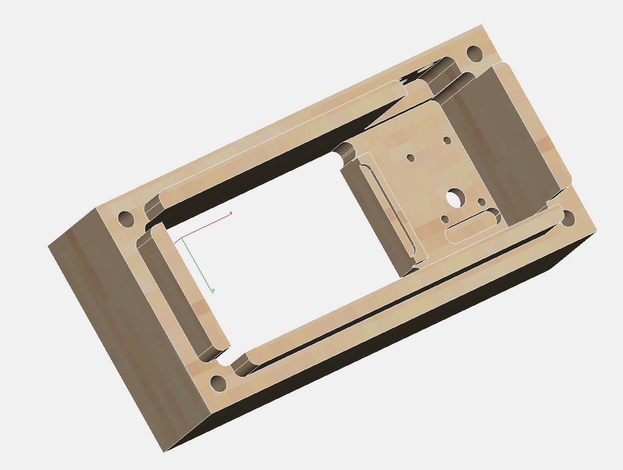
With these in mind, I started making my 3D model:
I’m pretty proud of how the printer module came out. I built the computer model using the physical model as a reference, and it’s a pretty good likeness. I’m getting better with ViaCAD.
It was only after completing this model that I realized that I had already broken one of my rules. There is no way for a 3 axis CNC to do all of these features at once. While most of the details are on the inside of the front cover, the hole for the camera would have to be cut as a separate process. More importantly, the holes in the top and side for the UI elements and charger port would need to be additional actions. My CNC isn’t even tall enough to drill the charger port since the box would need to be stood on end, so that one at least would need to be done by hand.
I resolved that this was all possible; it would just require some planning. Step one was finding some stock.
As you’ve already figured out, I settled on wood. Walnut to be exact. When I started, I knew that metal would be ridiculous, and I had trouble finding a good price on a large chunk of millable plastic. Instead, I drove down to the local woodworking supply store and bought some walnut blocks out of the scrap bin for $8/pound.
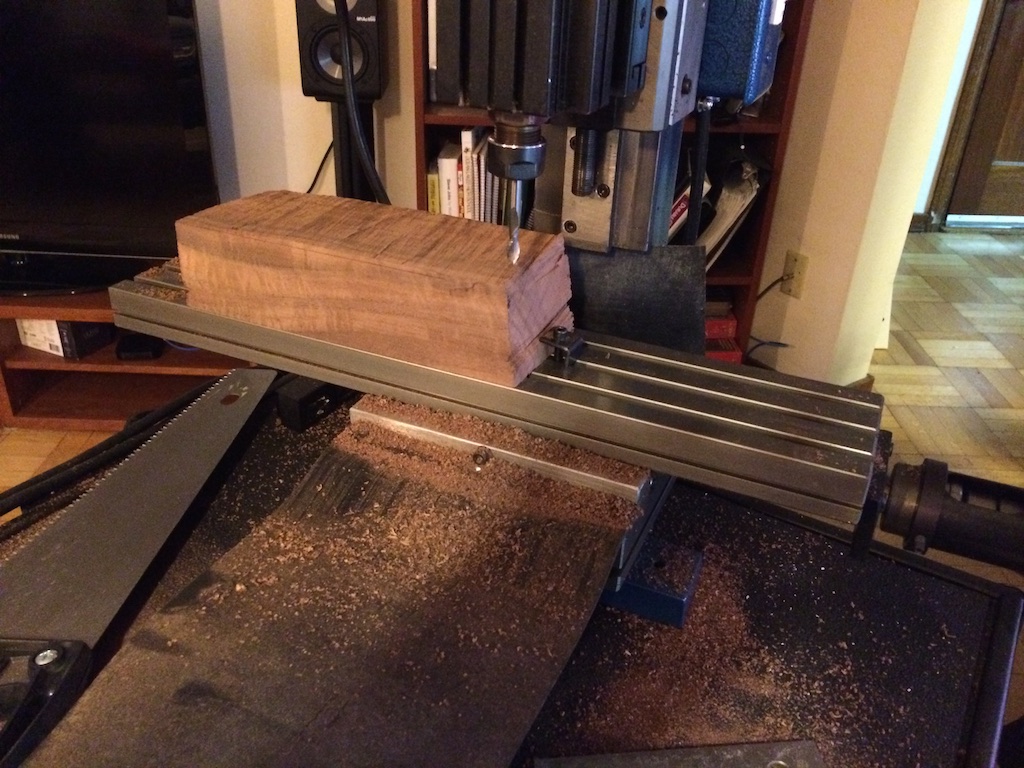
That’s a big block of wood.
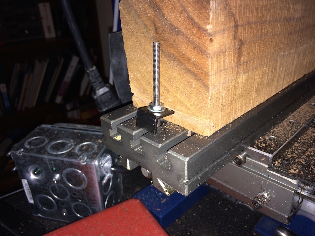
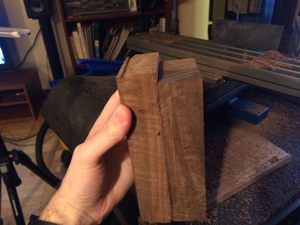
So big in fact, that none of my clamps were big enough to hold it. Because the stock had more material on the sides than what I needed, I sacrificed some of this material and used a saw to cut some grooves that gave me a good spot to grip with a clamp.
The next morning, I cut a good half-inch or so of wood off the top with a hand saw. It may not seem like a lot, but even with big step heights, my largest bit (1/4″) takes a long time to clear off that much material.
It was at this point that I actually measured the blocks of wood and found that they were about 2mm too narrow for my model. My 3D model has wall thicknesses of about 10mm though, so I figured I had plenty of extra space to work with. After all, all of the important mating and mounting features were on inside. Because I was dealing with wood, I could cut, sand, and buff out any imperfections on the outside surfaces.
The first side turned out pretty well:
Except for one small thing…
You’ll notice that there are supposed to be four mating features sticking out of the back of this part to mate with the other half of the camera. The top feature is missing from the finished part. This is where I learned something really interesting about CAMBAM.
CAMBAM is the software I use to convert STL files (3D models) to tool movements that the CNC machine can understand (gcode). There are a bazillion algorithms that can be used for this process, but the best that CAMBAM has to offer is “waterline”. This involves removing material one layer at a time moving from top to bottom. It even has some optimizations which can make this go pretty quickly (for example, if there is a small hole, it will finish the hole to its final depth before moving on to similar depths in other areas).
The biggest problem with waterline is that the vertical resolution is directly proportional to cut time. If I have it set to remove 1mm of material at a time, the best level of precision I’m going to get in the vertical direction is 1mm. If I decrease this “step size”, it takes that many more passes to remove the material.
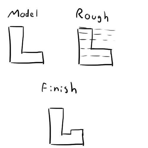
Fortunately, there’s a compromise. You can do a “waterline rough” pass first which makes large steps and removes all of the excess material, and then “waterline finish” pass which does smaller steps, but it doesn’t trace back over the material that’s already been removed. Here’s a little diagram to explain:
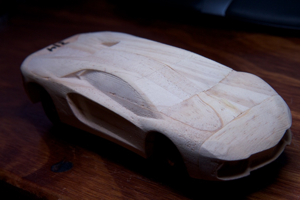
The red areas are the areas removed in each pass. For angled or smooth surfaces, this can actually achieve a very high resolution. I used this method to cheat in this year’s pinewood derby:
The problems arise when you have shapes with large flat sections. A roughing pass won’t get the correct height, but the finishing pass only focuses on the outer boundary of the step being cut. In other words, the finishing pass assumes that all of the inside material has already been removed. The result looks something like this:
This is a cross section of a piece with a large flat surface. The dotted lines represent the step size of the roughing pass. As you can see, the rough version doesn’t have the correct height on the platform.
When the finishing pass goes through, the tool only focuses on the outer edge of the removed material. As a result, you get a beautiful vertical surface cut to the right depth, but you still have a bunch of material left in the middle. This gives you a sort of channel around the platform that’s as wide as whatever cutting tool you’re using.
Unfortunately, CAMBAM isn’t smart enough to solve this out on its own, so you have to to coax it along. One method I came up with was to split the job into multiple tasks. Though the step size might not be precise, the target final depth for the task is always exact. Taking advantage of this, I made a separate task for each of the major large flat surfaces of my model and set the target depth to exactly the height of the associated surface.
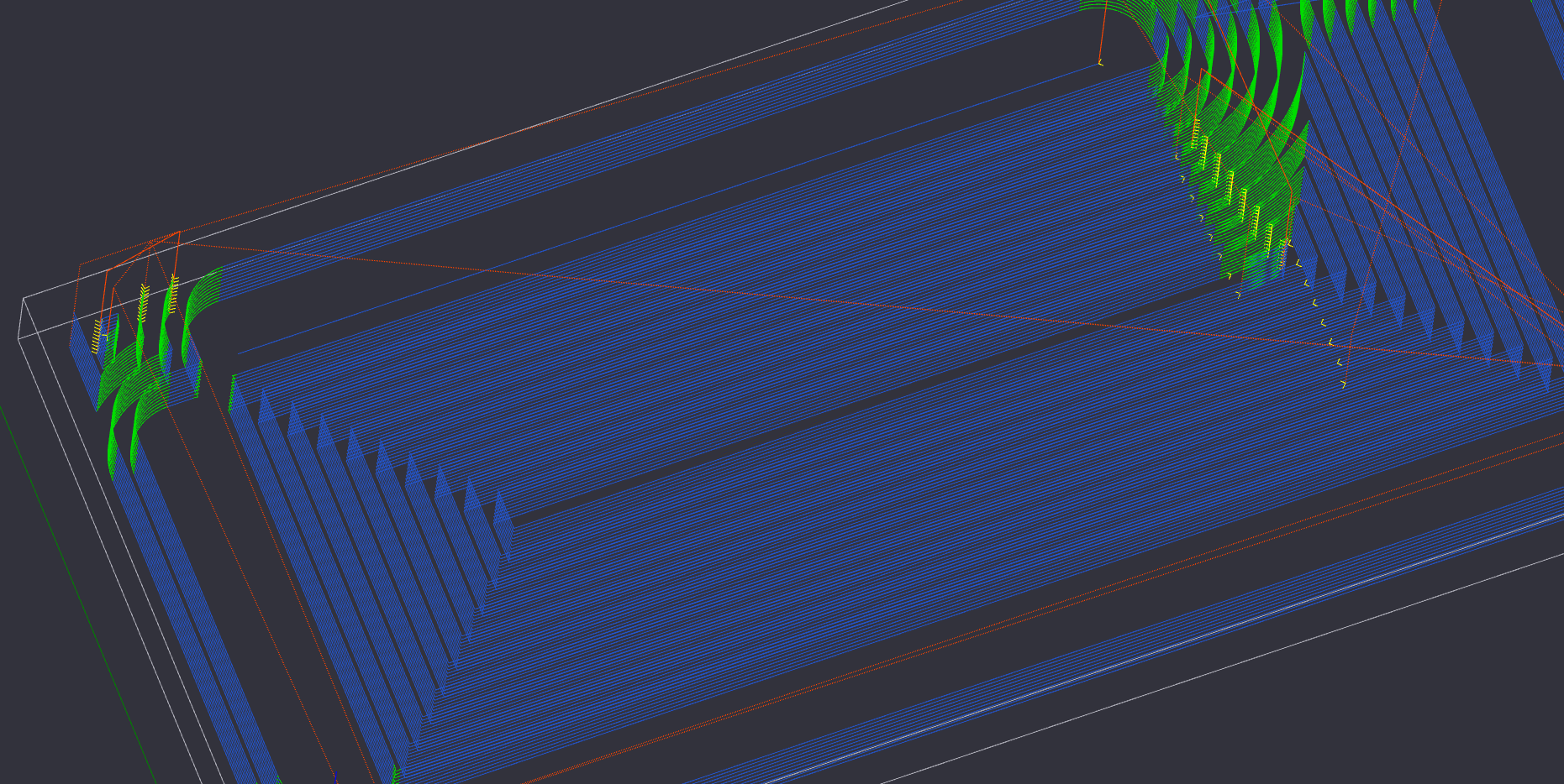
Apparently CAMBAM didn’t like this. Here’s the tool path it generated around my model:
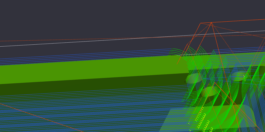
The blue and green lines represent the path of the head while it’s cutting while the red lines represent what the head is doing as it moves between cuts. If you look closely, you’ll notice that there’s one red line that disappears into the model:
Sure enough, CAMBAM decided to not only plunge the tool into this feature, but to move it down the length and completely disintegrate it.
It’s subtle, so I missed it until it was too late.
Since I had split the CNC job into separate tasks, this first section had a final target depth of 40mm from the table which should be perfectly level with the flat surface surrounding the mounting features.
Changing that final depth from 40mm to 40.000001mm solved the problem.
My guess is that there’s some kind of floating point bug in CAMBAM that makes it freak out when two numbers are exactly the same to infinite precision. Despite the small heart-attack I felt when my hour long CNC job started blowing big chunks of wood everywhere, the other three mating features were enough to keep everything aligned, and the extra space actually helps a little during assembly.
With the inside now cut, it was time to cut the lens feature and complete the printer mounting hole on the other side. I flipped the piece over and carefully aligned its long edge to the edge of the CNC table to make sure it was square. The piece was now just short enough to fit under my clamps.
The biggest challenge with doing multi-sided CNC is telling the computer exactly where your piece is so it knows where to start. Eyeballing it is never a good idea. Because I had flipped the piece over, there were no precision elements exposed on top that I could use for alignment. It was all uncut wood left over from the original scrap.
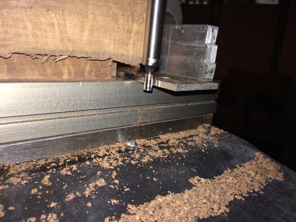
Using a parallel, I was able to align my edge finder with one of the mating features on the bottom of the piece.
That got me the X dimensions. For the Y dimension, I used the edge of the table which I had already aligned to the piece manually. I set zero Z to be at the level of the table.
With this all worked out, I very nervously hit go and let it do its work:
All things considered, it came out very well!
I didn’t grab any pictures of the second half of the camera, but it was a pretty easy single-sided job that went smoothly. When mated together, they now looked like this:
Like I said before, all the precision is on the inside surfaces, so I had a lot of leeway on the outside. Using a saw, I cut down the excess a little bit and started adding features. I planned to do a crazy amount of belt sanding once I had the whole thing put together.
I started with the easy stuff like drilling holes for the button, LED, and switch. The positions of these weren’t super critical, so I did a bit of measuring and mostly eyeballed it.
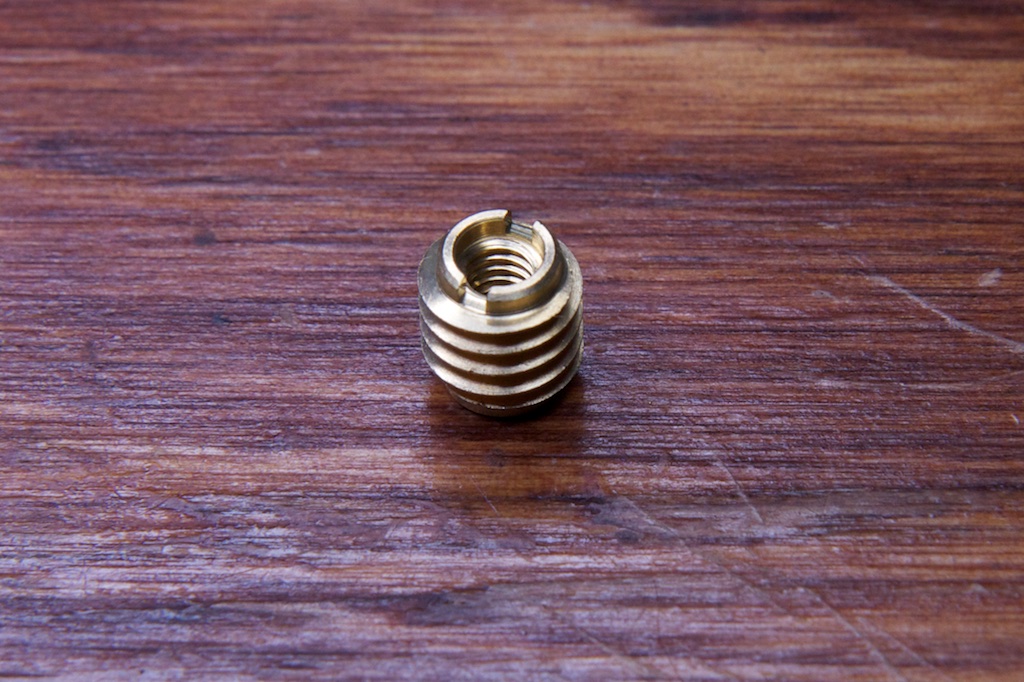
Next were the threaded inserts that would hold the two halves together. I picked up these from McMaster:
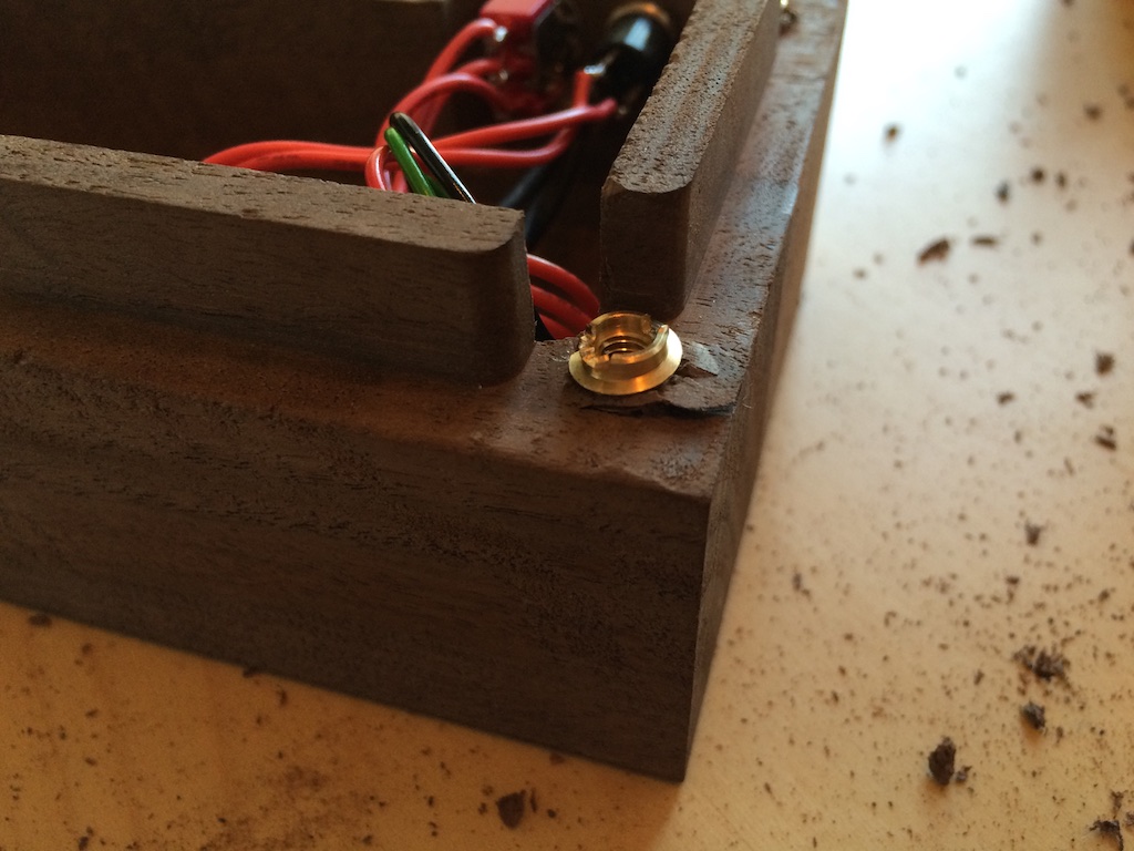
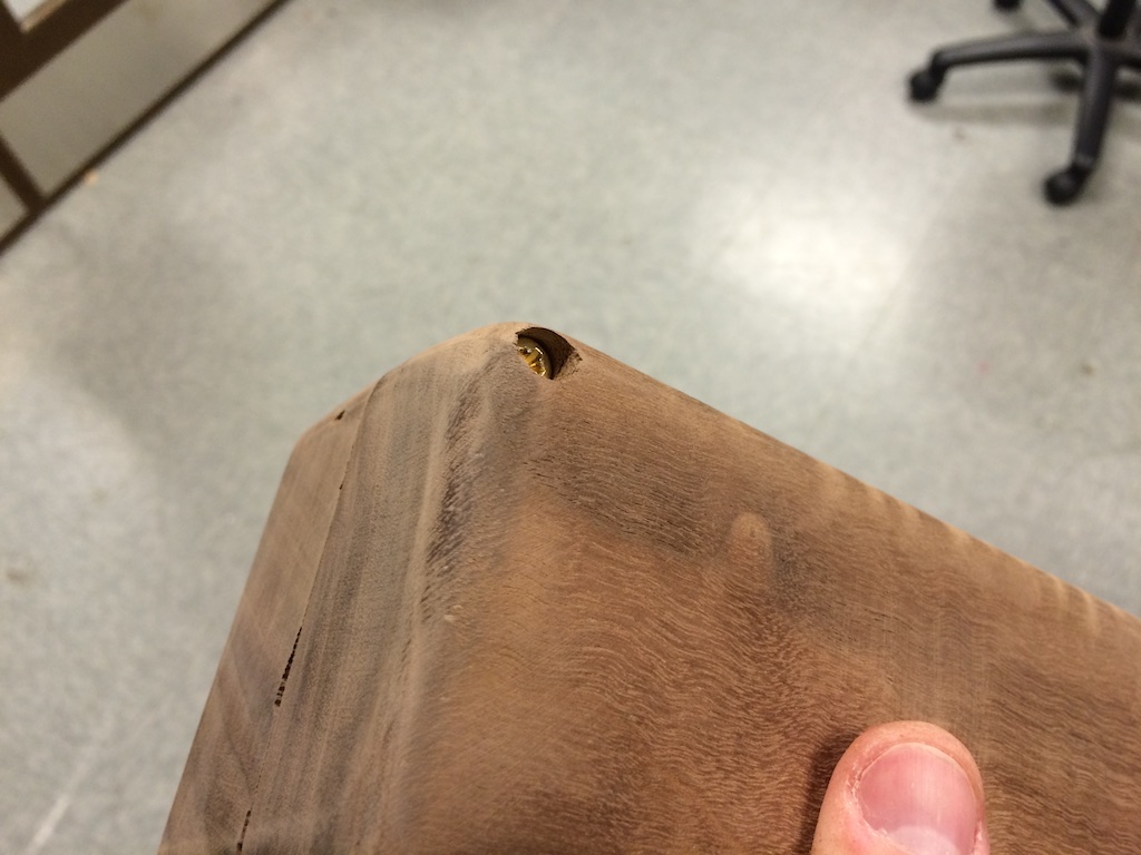
Their outside threads are meant to interface with the walls of a 1/4″ hole in a soft material like wood to anchor them in place. I had a little trouble with these guys. Firstly, they’re made out of brass which I chose for aesthetic reasons. Brass is super soft, and a lot of them broke when I tried to screw them in tightly. Secondly, the threads are a little too aggressive and splintered my wood in a few places:
Of the four, I only got one to go in all the way and sit flush with the surface. These things are a little overkill anyway, so what few threads sunk in were more than enough. I just countersunk the holes in the mating piece to accommodate them, and the two halves fit together well.
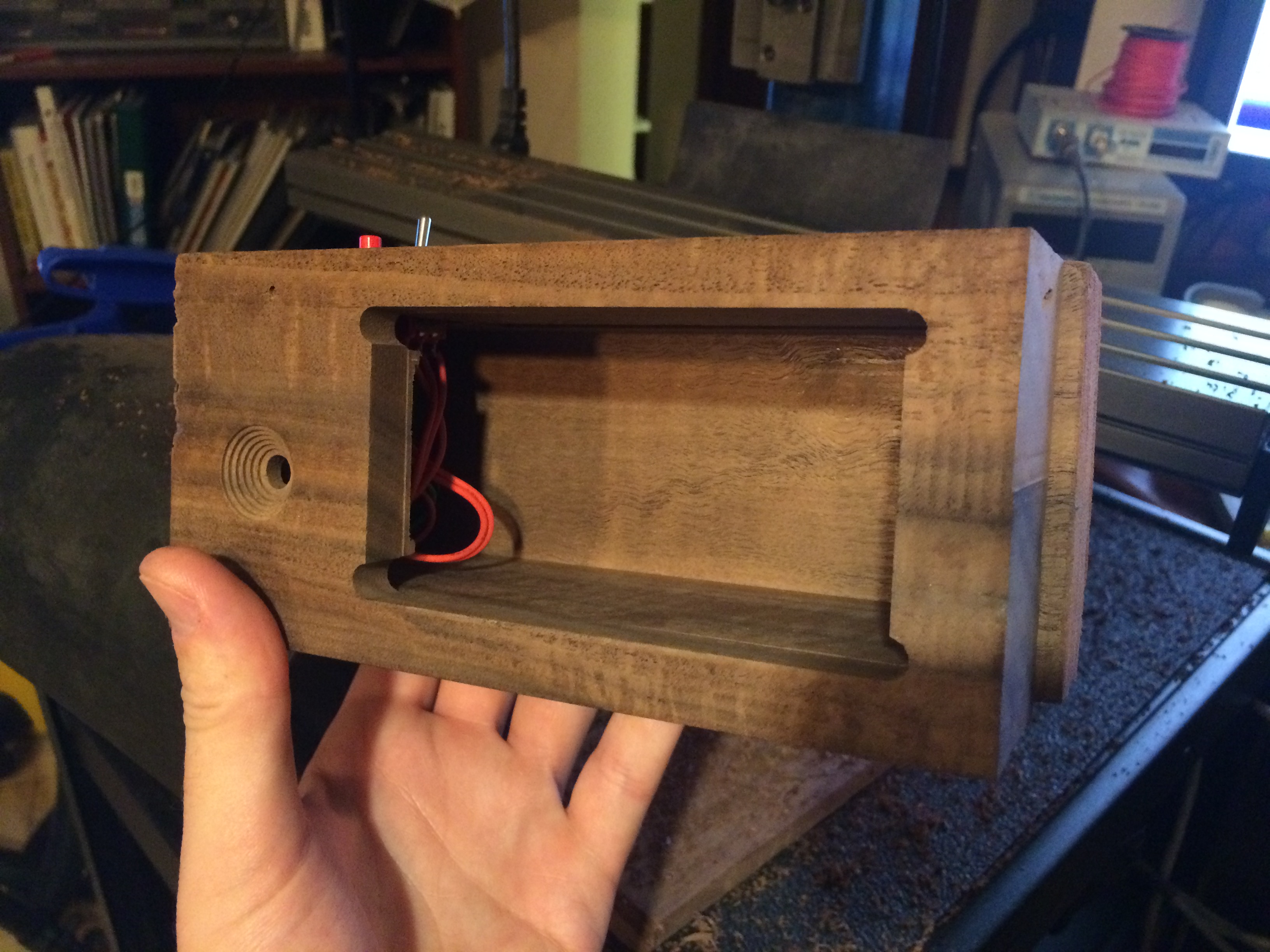
The holes for these threaded inserts were large enough to cut with the 1/4″ mill bit I used for everything else, but the holes in the mating side I had to do after the fact by hand. Aligning holes is always a scary experience, but it was pretty trivial in this case. I aligned my drill press head with the threaded inserts and clamped the piece down. Then I simply mated the second piece snugly to the first and let the built-in alignment features align the hole.
Four holes and four countersinks later and I had this:
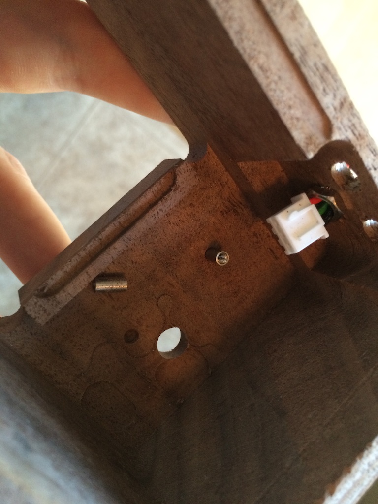
To secure the optical module in place, I used a different threaded insert that had no outside threads. The camera’s lens feature fit snugly in the hole I had drilled for it, so it held itself in place while I marked and drilled holes to a precise depth.
A little dab of super glue, and I had the mounting bosses in place. I could only get two of them in there as I couldn’t get my drill press that close to the edge of the box, but two is more than enough. Here it is halfway done.
If I do this again, I don’t think I’ll use the same threaded inserts for the case screws. A little bit of glue goes a long way when there’s so little stress on the enclosure, and the regular inserts were a lot easier to work with.
Next up came a LOT of belt sanding. I used a table sander and more or less just held the flat surfaces of the assembled box against the sander until things started to align. It really started to look good:
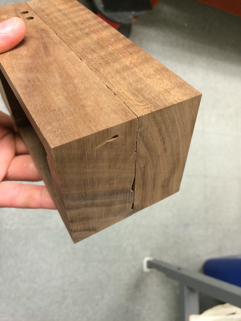
Though there were a few imperfections in the wood, it really had an awesome square look.
I always planned on sanding down the edges to be a little smooth, but I underestimated how fast belt sanders can remove material when they aren’t doing a whole surface at once. I got a little carried away, and in hindsight, I wish I had kept the square edges. Some of the edges look pretty bad:
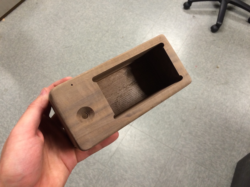
Though from far away, it looks decent:
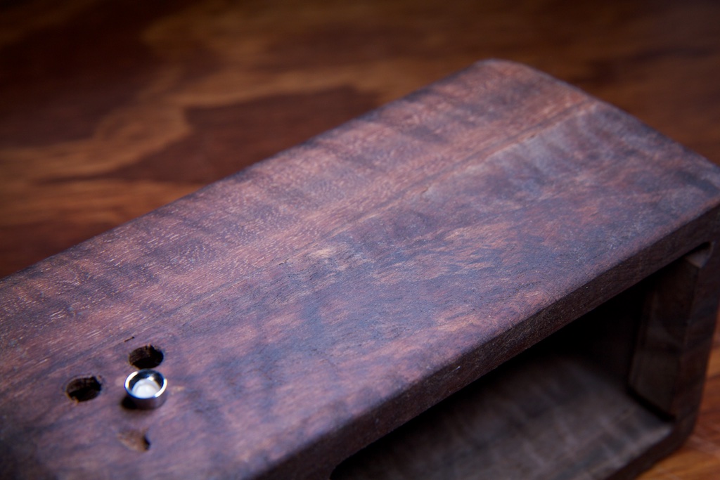
The only thing I had left to do was treat the outside of the wood to give it a nice durable finish. I bought a bottle of linseed oil and applied it using a rag to all of the outside surfaces. The result is great!









Pingback: Towards More Interesting Instant Cameras | Hackaday
Pingback: Towards More Interesting Instant Cameras - Tech key | Techzone | Tech data
Pingback: Towards More Interesting Instant Cameras | Ad Pub
Pingback: Towards More Interesting Instant Cameras | Hack The Planet
Pingback: Towards More Interesting Instant Cameras | 0-HACK
Thoughts about heading toward a KS project:
1. Separate the battery/charger from the camera/printer: Support attached and/or detached/cabled power, with standard LiPO standard and the option of a pack with replaceable/rechargeable NiMH cells (dirt cheap). Then, also offer the camera without a battery pack (DIY power is relatively easy if the interface is simple).
2. Personally, I’d want a clear case with all the internals visible, using standoffs and 3D-printed brackets where needed. Hopefully, this would also be the simplest/cheapest case.
3. Kit the custom parts and include a simple “no-solder” BOM for the rest. This permits a “partial gift” for the makers among us. And I certainly don’t mind giving Adafruit some business, especially if a small discount can be negotiated for this project’s BOM.
I think the above can provide a wider range of KS options and price levels with (hopefully) relatively little change to the core device.
Pingback: PrintSnap Wants to Bring Back the Instant Picture Using Dirt Cheap Receipt Paper
Hey there, I think this might interest you: http://www.sciencedaily.com/releases/2014/10/141022143628.htm
Yep, I’m well aware of that problem. I wash my hands compulsively anyway, and I’m sure someone will come around with a BPA-free option soon in response to public outcry. The same thing happened with Nalgene and leaded gasoline.
I want this! I want this soooo bad. Please sell me the first one!
Pingback: PrintSnap Wants to Bring Back the Instant Picture Using Dirt Cheap Receipt Paper - news from Allwebsolutions.net
When this becomes available, make sure it can be sent to Australia!!!!
Pingback: l’appareil photo instantanée le plus économique | news-apple
Hi Ch00f,
Your PA15 pin isn’t busted; the problem is that it is by default mapped as a JTAG debug pin and not to the GPIO block. In the device datasheet (the 100-page thing, NOT the 1000-page reference manual), there will be a “pin definitions” table near the front containing pin numbers for all the different package options, pin names (“PA15”), pin-types (“I/O”) and 5V-tolerance (“FT”), a “Main Function” column (this is the important part) and “Alternate Function” columns.
Note that for most GPIOs, the Main Function is GPIO, i.e. at power-on, PC12 is PC12, etc. However at power-on, PA15 is JTDI (jtag data in). This is necessary so that JTAG can start talking to a device when it boots. If you’re using SWD (and it seems you are) and want to make use of the PA15 pin, you need to disable the JTAG peripheral and its pin remapping.
Note that if you don’t want to be able to debug or maybe ever load code into the device again, you could also free up PA13 and PA14 which are the SWD pins.
Email me if you get stuck and I can send you the specific line of code you need; I just don’t have it here right now.
(I found this one out the hard way while playing with an stm32; I wasted a good 4 hours figuring it out)
THANK YOU
I figured it was something like that. I mentioned that part specifically hoping someone would figure it out for me.
Thanks for the tip!
Pingback: Prints for less than penny
Pingback: PrintSnap: A Home-Built Camera That Prints on Receipt Paper (and Almost for Free)
Pingback: The Quirky PrintSnap Instant Camera Let's You Create Instant Prints On The Cheap - DIY Photography
You are a silly man with silly ideas. As soon as I started the video I thought, “Why is he recreating the GameBoy Camera/Printer?” Your presentation was mockingly beautiful. It’s good to see your personal projects continue to be so whimsical.
What’s nice about the Cortex series is that some of the “peripherals” are standardized by ARM, so no matter the manufacturer, they’ll all behave the same. SysTick, FPU, NVIC, etc.
To enable the FPU, google “cortex m4 enable fpu” and you’ll find the following asm to do so (basically setting a couple bits to turn on the coprocessors in the coprocessor access control register):
; CPACR is located at address 0xE000ED88
LDR.W R0, =0xE000ED88
; Read CPACR
LDR R1, [R0]
; Set bits 20-23 to enable CP10 and CP11 coprocessors
ORR R1, R1, #(0xF << 20)
; Write back the modified value to the CPACR
STR R1, [R0]
I'm actually working on a project right now using a thermal print head, but rather than an all-in-one module like you have, I am using discrete components: a solenoid to push a kyocera print head onto the paper and a stepper motor to drive the paper through. I can print a 1450×672 px image in 3-5 seconds. In my case, going faster actually improves the quality of the print because the print head stays warm.
Pingback: PrintSnap: eine Sofortbildkamera, die Thermopapier statt PolaroidInstant-Film verwendet | Foto[gen]erell
I like this idea, the camera itself is sound for a version 1.0 project. To make it “sellable” you should consider a different housing altogether to make it look like an old school camera. Two ideas I thought are a TLR (like a Rollei) where the user looks down at a mirror to compose the image through a lens, while the camera is in a lens just below it, and the printer goes out the side. Another is a Brownie box camera style with an offset finder and the camera in a central front port. Either way something that looks like an old school film camera from a few feet away would be a winner.
Pingback: Una cámara DIY instantánea
Pingback: Una cámara DIY que hace fotografías instantáneas mas baratas que una Polaroid | Android 3G
Pingback: PrintSnap:用小票做相纸的黑白拍立得相机 | 趣火星
Pingback: PrintSnap Kamera Cetak Instan - Titikfokus
Pingback: Instant Camera Uses Receipt Rolls For Printing Paper - PSFK
Pingback: Instant Camera Uses Receipt Rolls For Printing Paper * The New World
Pingback: This instant camera will print images on a receipt paper roll - Berbit.net
This is fantastic! You basically made a spiritual successor to the King Jim Da Vinci DV55. I really want to see this becoming a real product and hope you go with Kickstarter on this project!
Pingback: This instant camera will print images on a receipt paper roll * The New World
Pingback: This instant camera will print images on a receipt paper roll | xoneta.com - majalah online gadget, komputer dan teknologi terbaru
please keep me posted on all news!
Pingback: PrintSnap, una cámara instantánea con la que imprimir fotografías en el papel de los tickets
Pingback: PrintSnap, una cámara instantánea con la que imprimir fotografías en el papel de los tickets | Fravala.com - Las noticias de tecnología a tu alcance.
Pingback: PrintSnap, una cámara instantánea con la que imprimir fotografías en el papel de los tickets - QuickIdeas
Pingback: PrintSnap, câmera instantânea para imprimir fotos em papel de tickets
Pingback: PrintSnap, una cámara instantánea con la que imprimir fotografías en el papel de los tickets • 25 noticias
Pingback: PrintSnap, a camera which prints the photo instantly | Minionvilla
please add me to your mailing list.
love it!!
i
Pingback: PrintSnap: an Instant Camera, which uses Receipt Paper instead of Polaroid/Instant Film |
I want this. If it’s become product please sell at JAPAN too.
I hope ship to Japan!
I’d like to buy it!
please send me all news about it.
l love it
ほしい!
これは楽しそう!
発売されたら買います 😀
Fantastic ! I love it !
Great! I want to buy one.
Great !!!!!! I want this.
Great!!
It must be goint to be a great tool.
I am really excited about it from now.
I want buy it!
it’s a fantastic invention Really hoping to the real product asap!!
Japan.Yokohama
great‼︎ please add me to your mailing list.
I love it !
Fantastic!
Please let me know your progress of the masterpiece.
soooo geate:)
i want this!!!
PrintSnap is very good.
I like it !
Please add me to your mailing list.
欲しいです!
I like this idea!
It’s fantastic!
Please add me to your mailing list
I remembered a pocket camera of Game Boy!
Wonderful.I wait for a followup!
The thing that is really cool. Commercialization sure if I want to carry one.
コレは面白い!!( ´ ▽ ` )ノ
I like it!
I WANT CAMERA!
Hi !
I like it !!!!
これは欲しい!
Please sell me the first one!
Very cool! Sell me as soon as possible!
販売したら購入検討したい、
興味があります、
Amazing….Please add me to your mailing list!!!!!
とても楽しそう!
booked
This is really amazing! I really want to have one! please add me in your mailing list.
I can’t wait for this on sale… 😀
cool
Good
I Want to buy this camera
Pls let me know any infos,
Pingback: PrintSnap – レシートの感熱紙にプリントできるインスタントカメラ | トイカメラ。【トイカメラとトイデジの情報】
Great!
I want it.
Pingback: PrintSnap is a Lo-Fi Polaroid that Uses Thermal Printing | Digital Trends
Pingback: PrintSnap instant camera concept uses receipt paper for low-cost solution - news from Allwebsolutions.net
Pingback: PrintSnap instant camera concept uses receipt paper for low-cost solution | TechnoTwitts | TechZone | Technology Updates | Gadgets Reviews
Pingback: PrintSnap instunt camera concep uses receipt pap'r fer loe-cost solushun zano mini drone | T'Redneck Revue
It is a great idea. This would be a great present for my 8 years old daughter who loves to take pictures. PLease make it at an acceptable price for normal people.
Thanks
Pingback: PrintSnap Instant Camera
This product concept is awesome!!
Plz add my name on your list!!
I’d love to buy!
Its fantastic! Let me know when is available!
Pingback: La “Polaroid” più economica di sempre, funziona con gli scontrini (foto)
this would be a hit on kickstarter, its totally geared towards the 20-30 something year old, new and upcoming product loving, crowd that kickstarter brings in. where are you based out of?
Hi ch00f!
We really like your “PrintSnap Instant Camera” project and want to cover it on EEWeb.com for our readers.
EEWeb.com is an online resource community site for Electrical Engineers and I’m sure that your project will be a great addition as an entry on our webpage.
Would it be ok, if we write an article about your project and include some pictures and other relevant materials?
We will give you credit for the project and link back to your site so our readers can learn more about you.
Hope to hear from you soon.
Regards,
Tin
Sure! Go for it. Send me a link when it’s up.
Hi! That’s good to hear. Thank you.
We will update you the moment the project is already live on our site.
I want this!
u got a great idea!
i want it!
I will buy this camera!!!
Please tell me as soon as you launch!
Pingback: Instant Camera, Instant Receipt Paper Pictures / Receipt Rolls Blog
I want this.. Hope you ship it in the Philippines
That is great use of thermal paper roll.haha~
It could be really nice if you can use your code to create something like an app for smartphone who can automatically dither the photo you take and send it to a bluetooth thermal printer !
Pingback: Actualidad: PolaPi es un fantástico homenaje a las Polaroid y está basada en una Raspberry Pi | Compu Vigilancia
Pingback: PolaPi es un fantástico homenaje a las Polaroid y está basada en una Raspberry Pi | Nuevo Titulo |
Pingback: PolaPi es un fantástico homenaje a las Polaroid y está basada en una Raspberry Pi | TecnologiaDigital
Pingback: PolaPi es un fantástico homenaje a las Polaroid y está basada en una Raspberry Pi | Ceo Bolivia
Pingback: PolaPi es un fantástico homenaje a las Polaroid y está basada en una Raspberry Pi - TodoMovil
Pingback: PolaPi es un fantástico homenaje a las Polaroid y está basada en una Raspberry Pi - InformeGeek
Pingback: PolaPi es un fantástico homenaje a las Polaroid y está basada en una Raspberry Pi
Pingback: PolaPi es un fantástico homenaje a las Polaroid y está basada en una Raspberry Pi - ChatNews
Pingback: PolaPi es un fantástico homenaje a las Polaroid y está basada en una Raspberry Pi - FM Centro
Pingback: PolaPi es un fantástico homenaje a las Polaroid y está basada en una Raspberry Pi - Point Fusion
Pingback: PolaPi es un fantástico homenaje a las Polaroid y está basada en una Raspberry Pi | Noticias: TecnoAR - Agencia Diseño Grafico & Web
Pingback: PolaPi es un fantástico homenaje a las Polaroid y está basada en una Raspberry Pi | Dellthus – Noticias
Omg..I love it … I hope it becomes available soon..
U rock!!!
me to 😉
Pingback: Electrolytic capacitors and preserving a family heirloom | ch00ftech Industries
how could i get one ? looks wonderful
Pingback: Las maravillas de Raspberry Pi! – Tara2
Pingback: Animated EVSE | ch00ftech Industries
I think is a great invention alright i never would have come up with that idea ist nice to see other beings like myself that are creative that think outside of the box that are not ordinarily “bookends fir i have made inventions too like a mammoth gunboat whitter folder pocket knife which you cant put in your pocker most of the components are made of wood the spring is made of pernabucco which us primarily made for the use of violin bows because of its incredible inert retention
Ability the only metal is the blade itself from a barbecue cutlery set that the handle
Rotted and I revamped the blade. Total length is approx a foot and a half Ebony Gabon is used for the stationary retainer and pivot pin I hope i did noi talk your ear off ps. Ive been meaning to contact case cutlery because they are ineed of engineers and a friend up the street also is creative in this field he is very adequate when it comes to tolerances he helped me with ideas in design just by his influence and knowledge.
buyc4nmd
Adriana want to play with you! Start Play: http://inx.lv/GkWu?h=232b90475fdf0370aff47b90c32afc97-
All the girls from next door are here with their cams! Visit Cam: http://inx.lv/GkWu?h=87f2146818a32dde5b520da579bff5e5-
i0sng2
d2yxk7
mm9fxk
ltecxy
yfy729
wzhihc
xp93r9
wasxgk
Pingback: Medicine Rehab Center – How To Choose The Best One – Scrum Leads
ccdgik
fl9ypr
xyvfmz
wmivkp
6f03jc
jwhpmv
bnc440
4anxbp
7suh3h
6ya14k
lgxwbh
oktb3c
65q5tb
ejn76b
4jfgi1