An ARM and a Leg
With a clear goal ahead of me, I trudged my way through a mountain of documentation and sample projects to figure out how to best get an ARM processor working. I’ll spare you the details of the hundreds of missteps along the way (I also forgot most of them) and try to outline what I used to get what I now have working.
Of the three brands I had available (Texas Instruments, ST Micro, and Atmel), I decided to use ST Micro’s STM32F4 Discovery board. I’m sure the other two are just as awesome, but a lot of my friends have experience with ST parts, so I thought it’d be a good place to start. Besides, if I blew it up, it’s pretty cheap to replace at just fifteen dollars. Plus, the board has an integrated debugger that can even be used to debug external boards.
The first thing I needed to do was get my toolchain set up. I’m not a huge fan of graphical IDEs, and a lot of them don’t work on OS X anyway, so after some searching, I discovered that I needed arm-none-eabi-gcc to compile my code and openocd and gdb to program it. I don’t remember much from installing these applications which probably means that it went smoothly. I think I used Brew, but there are a ton of ways to get it to work.
Arm-none-eabi-gcc works similarly to AVR-GCC, but openocd and gdb were new. One of the greatest benefits to using a modern processor is the ability to use modern debugging tools. Openocd can be configured to open a connection with the built-in debugging hardware through the ST-Link interface, and gdb can then probe around and read register values or pause and unpause the application. This was enormously useful compared to my usual “make this LED blink” method of debugging.
Once my toolchain was set up, I found it pretty easy to communicate with the Discovery board. Openocd came preinstalled with a profile called stm32f4discovery.cfg that had everything ready to go for my development kit.
With the hardware portion figured out, I looked around for software. ST has a standard peripherals library (more on that later), but I found it a little overwhelming and eventually settled on this GIT project which had simply ripped the GPIO toggle project out of the standard peripheral library and configured it to work on its own. The STM32F4 Discovery has its own built-in ST-link programmer, and using a few guides I found online like this one, I was well on my way. I even found an example Makefile that had some compile options at the bottom that allowed me to program my device by using the command “make openocd” and connect the debugger using “make gdb” in another window.
This left me with two options for debugging. Openocd calls on a local file openocd.cfg which tells it what to do. If that file ends in “program main.elf verify reset”, it connects to the chip, programs it, and resets. If that line is commented out, it just connects and stays connected requiring me to attach to the session using gdb in another terminal window. Gdb is similarly configured using a local file called “.gdbinit”. openocd by itself just programs the device while the combination of the two allows for real debugging.
This was more or less what I used for the entire first half of my project. Once I was satisfied with my proof of concept code, I created my own PCB with a different processor.
The Discovery board is powered by an STM32F407 processor which is a Cortex M4 that’s probably a little overpowered for what I needed. Realistically, the part is still pretty cheap and it would have been easier to keep everything the same as it was in the development kit, but I was worried that if I didn’t learn how to port code to a properly chosen processor early, I might end up using the F407 as a crutch for all my future projects.
I settled on the STM32f105 for my custom design. This is a Cortex M3 part which is about half the cost of the F407 and has fewer extraneous pins to worry about. Getting it to work of course required using the Standard Peripherals Library mentioned before which actually turned out to not be that bad.
I downloaded the library from here and unzipped it. This library contains code for the entire assortment of STM32F10x parts. Inside the Project/STM32F10x_StdPeriph_Examples/GPIO folder, I found the familiar IOToggle project in its original form which included a few source files and a readme recommending I “Copy all source files to the template folder under Project/STM32F10x_StdPeriph_Template”. The template folder had a few files for various toolchains, but I didn’t see anything that looked familiar.
The solution I used involved copying the new files to my Discovery template and replacing their counterparts. The project folder contains three sub-folders. “src” contains all of the .c files, “inc” holds all of the .h files, and “lib” has the peripheral library files. The lib folder has its own Makefile and compiles the special processor-specific functions separately from the main application code. If the main Makefile and the lib Makefile are configured correctly, this all happens automatically, and the compiler knows when to drag these special functions into the code that gets programmed to the part.
Of course, this didn’t compile on the first try. I had to modify all references to the F407 in my source code as well as the configuration of openocd. I also got some errors when compiling telling me that the library needed to be configured for my specific part. I needed to uncomment some lines in the file stm32f10x.h to let the library know that I was using a “connectivity line” device (more info in AN2557).
This all started working after my second attempt of going through it. I was happy to find that the library is incredibly well organized, and if you do a few things correctly, it tends to just work. There are a lot of specific details that I’m leaving out, so if you’d like to know more, I recommend downloading my project files and poking around. The Makefiles have a bunch of settings that I honestly don’t 100% understand at this point, and there were a few small tweaks I needed to perform to the library to set things like my processor speed. I can say that the library is well commented, and I usually didn’t need to look any further than a header file to figure out how to configure something.
Hardware
Printer
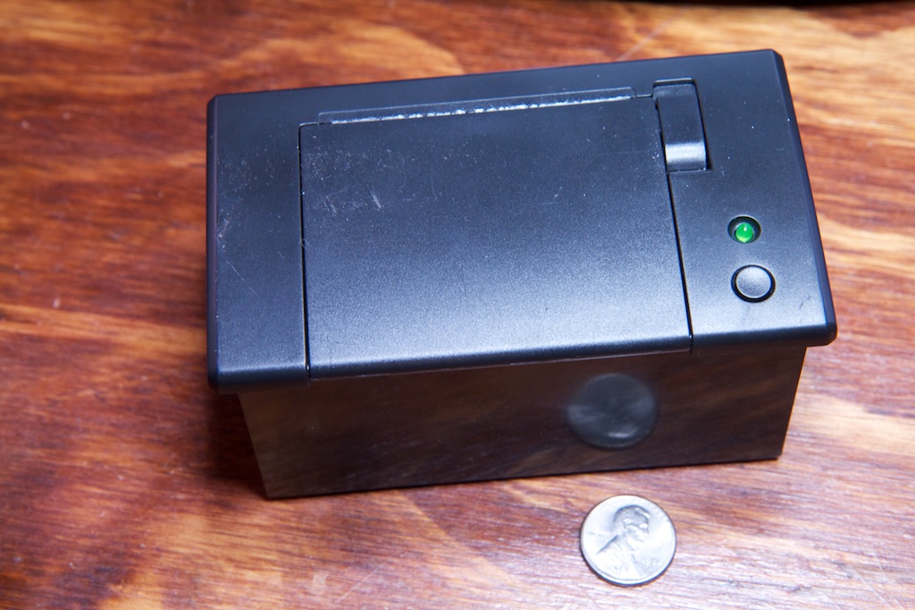
Thermal printer modules are actually pretty hard to find by themselves. There are a ton of thermal printers out there, but unless you want a full-on label or receipt printer complete with power cable and case, you have to hunt. There are a few options available from sellers on eBay who probably rip them out of the aforementioned thermal printers, but I ended up using the one offered by Adafruit as it was sure to have the best documentation.
Though it didn’t come with a proper datasheet, the example project provided by Adafruit outlined all of the necessary commands including most importantly, some decent default configuration settings for things like motor speed and heater temperature. There are actually a lot of levers you can pull on these printers, so it was nice to have a baseline that offered at least decent performance.
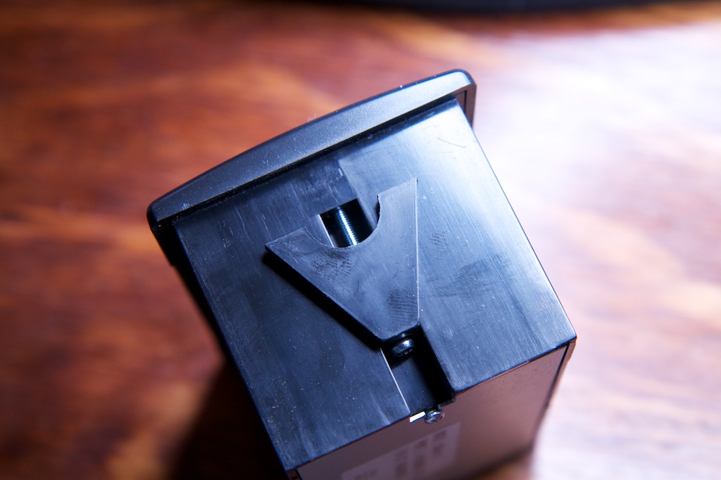
It has an attractive front face with an easy to open paper loading door, and most importantly, it has hardware to mount the printer into a panel. I’m not sure what it’s meant to mount to exactly, but the 0.5″ thick mounting surface I made for it proved to be just barely too thick. I resolved that by getting some 30mm M2.5 screws.
Datasheet here.
The printer doesn’t come with any thermal paper, so I ran across the street to the drugstore to pick up a roll of calculator paper for testing. Unfortunately, they only had 100′ rolls which wouldn’t fit, so I unraveled half. I then quickly learned that logging calculators do not use thermal paper. They have an ink-ribbon and print on normal paper, so with 50 feet of unraveled paper around my ankles, I went to Amazon and ordered 50 rolls of thermal paper for $20.
Camera
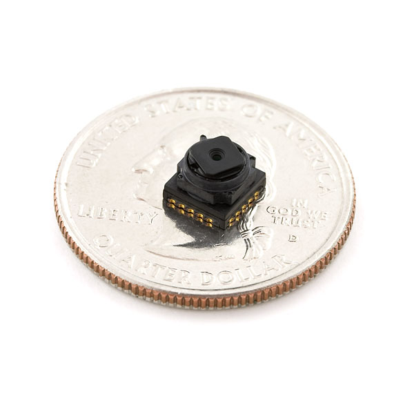
When I first started this project, I was planning on using a camera module that I had purchased years prior. Sparkfun used to offer an adorable tiny little CMOS camera module for something like $8, and I had purchased a few for a different project that never got off the ground.
Unfortunately, I think I brought my box of camera modules to some hack-a-thon thing I was participating in while I was in the process of moving, so after about three hours of frantic looking, I concluded that they are lost forever. Oh well, they had terrible documentation anyway.
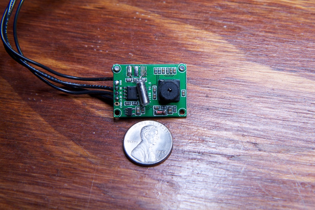
I instead settled on another Adafruit offering, their JPEG camera:
(Seen here after I accidentally ripped off the crystal oscillator). This guy was especially nice because they offered a few sample images that let me test out my code before even hooking it up.
Not the greatest, but good enough.
The camera module is a JPEG camera meaning that it doesn’t spit out data pixel by pixel. Instead, an onboard FPGA compresses the entire image to JPEG format and transmits that over serial. Since I’m just getting used to dealing with file systems, I was surprised to find that simply saving the raw data transmitted over serial to a file and giving that file the .jpg extension is all you need to do to create a JPEG file. In fact, the included Arduino library does exactly that as an Arduino is not powerful enough to decompress a JPEG in any reasonable amount of time.
Communication protocol datasheet here.
On-board video processor datasheet here.
Battery
This camera wasn’t going to be any fun if it needed to be wall-powered, and the printer required “5-9V” at something like 1-2A. That’s a decent amount of power. I guess I shouldn’t be surprised. The Gameboy Printer required six AA batteries to operate.
The minimum 5V requirement wasn’t going to let me use a standard 3.7V lithium polymer cell. I could have used some step-up circuitry, but this could have been difficult due the erratic current draw of the printer. Really, it wouldn’t have been impossible, but since the printer didn’t need a specific voltage (testing showed that it worked anywhere within that range), I thought it would be easier to connect it directly to a dual-cell battery with no regulation whatsoever.
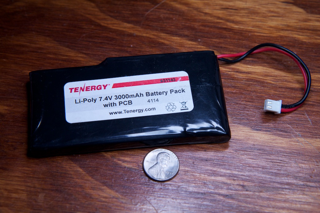
This thing is a monster. It’s seriously terrifying. 7.4V, 3000mAh, and continuous rated discharge of 4A. That means that it can continuously put out 28 watts. That’s almost 30 watts!
Usually with series cell batteries, there’s a requirement to keep the cells balanced. Without proper balancing, one cell can wear out faster than the other, and since they’re in series, power has to shut off when the first cell reaches the minimum discharge voltage even if the other one still has more charge to offer.
This pack was built to order, so I’m guessing that they’ve either included some kind of balancing circuitry inside the pack, or the cells they chose are of a specifically matched chemistry to prevent disparity in cell wear. All I need to worry about is that it charges to 8.4V and discharges to 6. It even has built-in battery protection circuitry!
Battery datasheet here.



Pingback: Towards More Interesting Instant Cameras | Hackaday
Pingback: Towards More Interesting Instant Cameras - Tech key | Techzone | Tech data
Pingback: Towards More Interesting Instant Cameras | Ad Pub
Pingback: Towards More Interesting Instant Cameras | Hack The Planet
Pingback: Towards More Interesting Instant Cameras | 0-HACK
Thoughts about heading toward a KS project:
1. Separate the battery/charger from the camera/printer: Support attached and/or detached/cabled power, with standard LiPO standard and the option of a pack with replaceable/rechargeable NiMH cells (dirt cheap). Then, also offer the camera without a battery pack (DIY power is relatively easy if the interface is simple).
2. Personally, I’d want a clear case with all the internals visible, using standoffs and 3D-printed brackets where needed. Hopefully, this would also be the simplest/cheapest case.
3. Kit the custom parts and include a simple “no-solder” BOM for the rest. This permits a “partial gift” for the makers among us. And I certainly don’t mind giving Adafruit some business, especially if a small discount can be negotiated for this project’s BOM.
I think the above can provide a wider range of KS options and price levels with (hopefully) relatively little change to the core device.
Pingback: PrintSnap Wants to Bring Back the Instant Picture Using Dirt Cheap Receipt Paper
Hey there, I think this might interest you: http://www.sciencedaily.com/releases/2014/10/141022143628.htm
Yep, I’m well aware of that problem. I wash my hands compulsively anyway, and I’m sure someone will come around with a BPA-free option soon in response to public outcry. The same thing happened with Nalgene and leaded gasoline.
I want this! I want this soooo bad. Please sell me the first one!
Pingback: PrintSnap Wants to Bring Back the Instant Picture Using Dirt Cheap Receipt Paper - news from Allwebsolutions.net
When this becomes available, make sure it can be sent to Australia!!!!
Pingback: l’appareil photo instantanée le plus économique | news-apple
Hi Ch00f,
Your PA15 pin isn’t busted; the problem is that it is by default mapped as a JTAG debug pin and not to the GPIO block. In the device datasheet (the 100-page thing, NOT the 1000-page reference manual), there will be a “pin definitions” table near the front containing pin numbers for all the different package options, pin names (“PA15”), pin-types (“I/O”) and 5V-tolerance (“FT”), a “Main Function” column (this is the important part) and “Alternate Function” columns.
Note that for most GPIOs, the Main Function is GPIO, i.e. at power-on, PC12 is PC12, etc. However at power-on, PA15 is JTDI (jtag data in). This is necessary so that JTAG can start talking to a device when it boots. If you’re using SWD (and it seems you are) and want to make use of the PA15 pin, you need to disable the JTAG peripheral and its pin remapping.
Note that if you don’t want to be able to debug or maybe ever load code into the device again, you could also free up PA13 and PA14 which are the SWD pins.
Email me if you get stuck and I can send you the specific line of code you need; I just don’t have it here right now.
(I found this one out the hard way while playing with an stm32; I wasted a good 4 hours figuring it out)
THANK YOU
I figured it was something like that. I mentioned that part specifically hoping someone would figure it out for me.
Thanks for the tip!
Pingback: Prints for less than penny
Pingback: PrintSnap: A Home-Built Camera That Prints on Receipt Paper (and Almost for Free)
Pingback: The Quirky PrintSnap Instant Camera Let's You Create Instant Prints On The Cheap - DIY Photography
You are a silly man with silly ideas. As soon as I started the video I thought, “Why is he recreating the GameBoy Camera/Printer?” Your presentation was mockingly beautiful. It’s good to see your personal projects continue to be so whimsical.
What’s nice about the Cortex series is that some of the “peripherals” are standardized by ARM, so no matter the manufacturer, they’ll all behave the same. SysTick, FPU, NVIC, etc.
To enable the FPU, google “cortex m4 enable fpu” and you’ll find the following asm to do so (basically setting a couple bits to turn on the coprocessors in the coprocessor access control register):
; CPACR is located at address 0xE000ED88
LDR.W R0, =0xE000ED88
; Read CPACR
LDR R1, [R0]
; Set bits 20-23 to enable CP10 and CP11 coprocessors
ORR R1, R1, #(0xF << 20)
; Write back the modified value to the CPACR
STR R1, [R0]
I'm actually working on a project right now using a thermal print head, but rather than an all-in-one module like you have, I am using discrete components: a solenoid to push a kyocera print head onto the paper and a stepper motor to drive the paper through. I can print a 1450×672 px image in 3-5 seconds. In my case, going faster actually improves the quality of the print because the print head stays warm.
Pingback: PrintSnap: eine Sofortbildkamera, die Thermopapier statt PolaroidInstant-Film verwendet | Foto[gen]erell
I like this idea, the camera itself is sound for a version 1.0 project. To make it “sellable” you should consider a different housing altogether to make it look like an old school camera. Two ideas I thought are a TLR (like a Rollei) where the user looks down at a mirror to compose the image through a lens, while the camera is in a lens just below it, and the printer goes out the side. Another is a Brownie box camera style with an offset finder and the camera in a central front port. Either way something that looks like an old school film camera from a few feet away would be a winner.
Pingback: Una cámara DIY instantánea
Pingback: Una cámara DIY que hace fotografías instantáneas mas baratas que una Polaroid | Android 3G
Pingback: PrintSnap:用小票做相纸的黑白拍立得相机 | 趣火星
Pingback: PrintSnap Kamera Cetak Instan - Titikfokus
Pingback: Instant Camera Uses Receipt Rolls For Printing Paper - PSFK
Pingback: Instant Camera Uses Receipt Rolls For Printing Paper * The New World
Pingback: This instant camera will print images on a receipt paper roll - Berbit.net
This is fantastic! You basically made a spiritual successor to the King Jim Da Vinci DV55. I really want to see this becoming a real product and hope you go with Kickstarter on this project!
Pingback: This instant camera will print images on a receipt paper roll * The New World
Pingback: This instant camera will print images on a receipt paper roll | xoneta.com - majalah online gadget, komputer dan teknologi terbaru
please keep me posted on all news!
Pingback: PrintSnap, una cámara instantánea con la que imprimir fotografías en el papel de los tickets
Pingback: PrintSnap, una cámara instantánea con la que imprimir fotografías en el papel de los tickets | Fravala.com - Las noticias de tecnología a tu alcance.
Pingback: PrintSnap, una cámara instantánea con la que imprimir fotografías en el papel de los tickets - QuickIdeas
Pingback: PrintSnap, câmera instantânea para imprimir fotos em papel de tickets
Pingback: PrintSnap, una cámara instantánea con la que imprimir fotografías en el papel de los tickets • 25 noticias
Pingback: PrintSnap, a camera which prints the photo instantly | Minionvilla
please add me to your mailing list.
love it!!
i
Pingback: PrintSnap: an Instant Camera, which uses Receipt Paper instead of Polaroid/Instant Film |
I want this. If it’s become product please sell at JAPAN too.
I hope ship to Japan!
I’d like to buy it!
please send me all news about it.
l love it
ほしい!
これは楽しそう!
発売されたら買います 😀
Fantastic ! I love it !
Great! I want to buy one.
Great !!!!!! I want this.
Great!!
It must be goint to be a great tool.
I am really excited about it from now.
I want buy it!
it’s a fantastic invention Really hoping to the real product asap!!
Japan.Yokohama
great‼︎ please add me to your mailing list.
I love it !
Fantastic!
Please let me know your progress of the masterpiece.
soooo geate:)
i want this!!!
PrintSnap is very good.
I like it !
Please add me to your mailing list.
欲しいです!
I like this idea!
It’s fantastic!
Please add me to your mailing list
I remembered a pocket camera of Game Boy!
Wonderful.I wait for a followup!
The thing that is really cool. Commercialization sure if I want to carry one.
コレは面白い!!( ´ ▽ ` )ノ
I like it!
I WANT CAMERA!
Hi !
I like it !!!!
これは欲しい!
Please sell me the first one!
Very cool! Sell me as soon as possible!
販売したら購入検討したい、
興味があります、
Amazing….Please add me to your mailing list!!!!!
とても楽しそう!
booked
This is really amazing! I really want to have one! please add me in your mailing list.
I can’t wait for this on sale… 😀
cool
Good
I Want to buy this camera
Pls let me know any infos,
Pingback: PrintSnap – レシートの感熱紙にプリントできるインスタントカメラ | トイカメラ。【トイカメラとトイデジの情報】
Great!
I want it.
Pingback: PrintSnap is a Lo-Fi Polaroid that Uses Thermal Printing | Digital Trends
Pingback: PrintSnap instant camera concept uses receipt paper for low-cost solution - news from Allwebsolutions.net
Pingback: PrintSnap instant camera concept uses receipt paper for low-cost solution | TechnoTwitts | TechZone | Technology Updates | Gadgets Reviews
Pingback: PrintSnap instunt camera concep uses receipt pap'r fer loe-cost solushun zano mini drone | T'Redneck Revue
It is a great idea. This would be a great present for my 8 years old daughter who loves to take pictures. PLease make it at an acceptable price for normal people.
Thanks
Pingback: PrintSnap Instant Camera
This product concept is awesome!!
Plz add my name on your list!!
I’d love to buy!
Its fantastic! Let me know when is available!
Pingback: La “Polaroid” più economica di sempre, funziona con gli scontrini (foto)
this would be a hit on kickstarter, its totally geared towards the 20-30 something year old, new and upcoming product loving, crowd that kickstarter brings in. where are you based out of?
Hi ch00f!
We really like your “PrintSnap Instant Camera” project and want to cover it on EEWeb.com for our readers.
EEWeb.com is an online resource community site for Electrical Engineers and I’m sure that your project will be a great addition as an entry on our webpage.
Would it be ok, if we write an article about your project and include some pictures and other relevant materials?
We will give you credit for the project and link back to your site so our readers can learn more about you.
Hope to hear from you soon.
Regards,
Tin
Sure! Go for it. Send me a link when it’s up.
Hi! That’s good to hear. Thank you.
We will update you the moment the project is already live on our site.
I want this!
u got a great idea!
i want it!
I will buy this camera!!!
Please tell me as soon as you launch!
Pingback: Instant Camera, Instant Receipt Paper Pictures / Receipt Rolls Blog
I want this.. Hope you ship it in the Philippines
That is great use of thermal paper roll.haha~
It could be really nice if you can use your code to create something like an app for smartphone who can automatically dither the photo you take and send it to a bluetooth thermal printer !
Pingback: Actualidad: PolaPi es un fantástico homenaje a las Polaroid y está basada en una Raspberry Pi | Compu Vigilancia
Pingback: PolaPi es un fantástico homenaje a las Polaroid y está basada en una Raspberry Pi | Nuevo Titulo |
Pingback: PolaPi es un fantástico homenaje a las Polaroid y está basada en una Raspberry Pi | TecnologiaDigital
Pingback: PolaPi es un fantástico homenaje a las Polaroid y está basada en una Raspberry Pi | Ceo Bolivia
Pingback: PolaPi es un fantástico homenaje a las Polaroid y está basada en una Raspberry Pi - TodoMovil
Pingback: PolaPi es un fantástico homenaje a las Polaroid y está basada en una Raspberry Pi - InformeGeek
Pingback: PolaPi es un fantástico homenaje a las Polaroid y está basada en una Raspberry Pi
Pingback: PolaPi es un fantástico homenaje a las Polaroid y está basada en una Raspberry Pi - ChatNews
Pingback: PolaPi es un fantástico homenaje a las Polaroid y está basada en una Raspberry Pi - FM Centro
Pingback: PolaPi es un fantástico homenaje a las Polaroid y está basada en una Raspberry Pi - Point Fusion
Pingback: PolaPi es un fantástico homenaje a las Polaroid y está basada en una Raspberry Pi | Noticias: TecnoAR - Agencia Diseño Grafico & Web
Pingback: PolaPi es un fantástico homenaje a las Polaroid y está basada en una Raspberry Pi | Dellthus – Noticias
Omg..I love it … I hope it becomes available soon..
U rock!!!
me to 😉
Pingback: Electrolytic capacitors and preserving a family heirloom | ch00ftech Industries
how could i get one ? looks wonderful
Pingback: Las maravillas de Raspberry Pi! – Tara2
Pingback: Animated EVSE | ch00ftech Industries
I think is a great invention alright i never would have come up with that idea ist nice to see other beings like myself that are creative that think outside of the box that are not ordinarily “bookends fir i have made inventions too like a mammoth gunboat whitter folder pocket knife which you cant put in your pocker most of the components are made of wood the spring is made of pernabucco which us primarily made for the use of violin bows because of its incredible inert retention
Ability the only metal is the blade itself from a barbecue cutlery set that the handle
Rotted and I revamped the blade. Total length is approx a foot and a half Ebony Gabon is used for the stationary retainer and pivot pin I hope i did noi talk your ear off ps. Ive been meaning to contact case cutlery because they are ineed of engineers and a friend up the street also is creative in this field he is very adequate when it comes to tolerances he helped me with ideas in design just by his influence and knowledge.
buyc4nmd
Adriana want to play with you! Start Play: http://inx.lv/GkWu?h=232b90475fdf0370aff47b90c32afc97-
All the girls from next door are here with their cams! Visit Cam: http://inx.lv/GkWu?h=87f2146818a32dde5b520da579bff5e5-
i0sng2
d2yxk7
mm9fxk
ltecxy
yfy729
wzhihc
xp93r9
wasxgk
Pingback: Medicine Rehab Center – How To Choose The Best One – Scrum Leads
ccdgik
fl9ypr
xyvfmz
wmivkp
6f03jc
jwhpmv
bnc440
4anxbp
7suh3h
6ya14k
lgxwbh
oktb3c
65q5tb
ejn76b
4jfgi1
mwzn56
aepe1z
ygq5w0
29p707
zxkt75
pwdpr3
cybyz4
hp06lu
7l5svh
jjczop
ybxp2h
tzq6mb
6qd6mu
9s41rm
0vhbos
xtu40i
ypor5s
l8wlfz
wxo2u3
891g1d
6o9440
00oxl5
dz5dsp
4dw9ym
eo1w6h
d1urv6
x0vve9
avd2j0
a9gijm
9yo1c8
qv53vq
gnbmef
pge085
4cg08t
fan8yp
gy5iak
0uoiaj
ijcpwb
hg7359
l0eef5
ftff0k
7q8wqe
j9rcsu
cccrjf
eyiuo4
tn158t
bvgc94
us9t3c
bs6cqn
r9q7hw
b419lh
tx7kv6
yuym7q
psfog9
51b6qv
cx8fri
nf8nii
kkdckp
9qj6lt
yl42a7
8a0irz
i94bt8
jn5dlt
f1rrml
tj9mke
ndmb6q
nk4hex
66ogpn
do8nn4
inhjdq
bo37x7
93llkc
0rs866
ypyxov
qf2ecu
f5kfjh
3edc9j
e059g9
r8k6o8
fwjdyr
hd3hot
ysrvka
czcaeg
jhy7ki
qn4v4c
49yghf
wl3o54
ageoz6
c2r2rk
spw0zi
qawz2h
tk47y2
5kf9r2
8wpn54
0rwkwg
lkxwkw
3xnw79
o1z19x
6o44zl
8tvvvc
bdk2rt
odysgo
q4dh21
ri3cek
lt7cfp
ddzts7
rccuqo
8d1c3x
8lsg7q
gpvzif
lryn7y
7nm79t
sclijn
rdz2hs
vtqi1w
l47ws5
0jf6wk
l27o0g
lhsh0j
ijcgqu
7m2tm2
mfzei2
vlu7kb
3aw9ow
rsopca
ealwcy
l5hs15
8rvdpk
ihzl48
bqoh0n
18qdwv
dbu7qw
g0sue8
59g6s9
g0picb
ht0xh7
3qdnre
tq6jix
2fa2vn
isuxtu
rgrr9x
b97kij
ki8wub
3xnxco
rqlqvq
4sjzw8
xbudx9
onf6kp
4bbqe1
8gdupt
ve0fib
s1nrx1
4rl01b
btq7sw
xetb3b
byduh8
fqbi4y
ox8l8s
bm9xai
hg3sfx
d3eldp
ntwwh2
iebwci
7sfamr
g6bdyg
g0q9fr
o4prem
zjkqlq
cj6oii
flvo2r
4jmc49
guaf6c
fq6fqg
2gk1ah
w8kkou
ewydb3
6g4dsn
ft6gg6
h3f55n
4c91ac
567rae
6y7ry3
9l95fe
k1lzxz
nxam5t
wr3pav
m4ne12
xwxlmo
lzynzc
julsen
Codezion Theme is a leading website theme selling platform offering beautifully crafted, fully responsive HTML templete designs—perfect for developers and businesses seeking fast, customizable solutions for any project.
78gsfs
ivfxss
1yfnus
y3hfo6
cpsluh
78evgq
su2aj1
lijqhv
49iprv
1f85xp
gnootd
kqag2c
3qozok
nyka41
rmwa42
xcub06
iicht6
xjpplj
2tz0a0
https://genuinetech.pk/
Best Diploma Short Courses in Lahore
Genuine Technology of computer college is one of the best colleges in Lahore, Pakistan. We provide all short course. This short course in computer college is designed to provide students with a fundamental understanding of essential computer skills and applications. It covers key topic Such as basic computer operations, Microsoft Office tools, (Word, Excel, PowerPoint), internet usage, email communication, and an introduction to computer hardware and software. This course is best for beginners or individuals looking to enhance their digital literacy for academic, professional or personal use. By the end of the course, student will be equipped with the practical skills needed to confidently use computers in everyday tasks.
pdah0h
3lckqe
ypbmcs
j32vfb
tq53pw
jnwhg7
419qhh
89hmz1
5v3u31
t2przi
bt0cl4
qq085g
orij2d
4dhdbt
f8uqsn
uxuphh
a5jw9r
58vt23
yoizzt
vemx0i
hoh10y
sjlbkx
du2v90
y3e65v
4rbdjy
4725us
g6nx24
gli0to
h1yxdc
61daad
5ijxh5
f7a13t
5rsd1r
mbh2j9
3lerrf
xg9a5s
645vu3
dgymon