Let me tell you a tale. 8 months and 18 days ago, on March 25, I was sent an email requesting a commissioned piece of electronic clothing similar to my DJ jacket for a musical performer to wear on stage. I mulled it over for a bit, and came up with the idea of a sound-reactive EL panel dimmer. Unlike most cheap “sound reactive” stuff that just blinks to music, I wanted my dimmer to allow for a more appealing pulsating effect.
EL panels are just like EL wire except instead of having a phosphorescent insulating tube wrapped around the inner wire in a coaxial pair, it has a sheet of the same material placed between two conductive sheets. They operate on the same principle: need 100V-ish AC input at
![]()
2kHz to light up. The only difference is that the panel, giving off more light, draws more power.
EL wires, panels, and other materials don’t seem to be generally well understood by the sources provided to me by the internet. I couldn’t find any good sources explaining how to make a dimmer, so I set out into uncharted water to come up with my own solution.
Almost two months after that email, I had created my first sound-reactive EL panel dimmer. While it was probably one of the most educational projects I’ve worked on, it was also the biggest disaster I’ve ever blogged about. The dimmer didn’t work very well. The panel wasn’t getting bright enough. I decided not to mail the dimmer to my client and instead try to figure out how to improve it (note the FAQ where it says that I don’t work well with deadlines). Since then, I’ve been writing a ton of posts detailing my experiments with EL wire: 1, 2, 3, 4, 5, 6, 7…
Well, I think I FINALLY HAVE IT! Okay, it’s not perfect. There were numerous ugly reworks required to make this work, and it still has some room for improvement, but as a proof of concept, it is totally done. I will probably only need one more short blog post after this to just show off a rebuilt version without all those ugly reworks.
Introduction
Though I did finally get a working product, it was only after a number of changes that I had to be made along the way. In this post, I plan to not only outline how the final thing works but also describe what mistakes I made and what I learned from them.
Initial Schematic
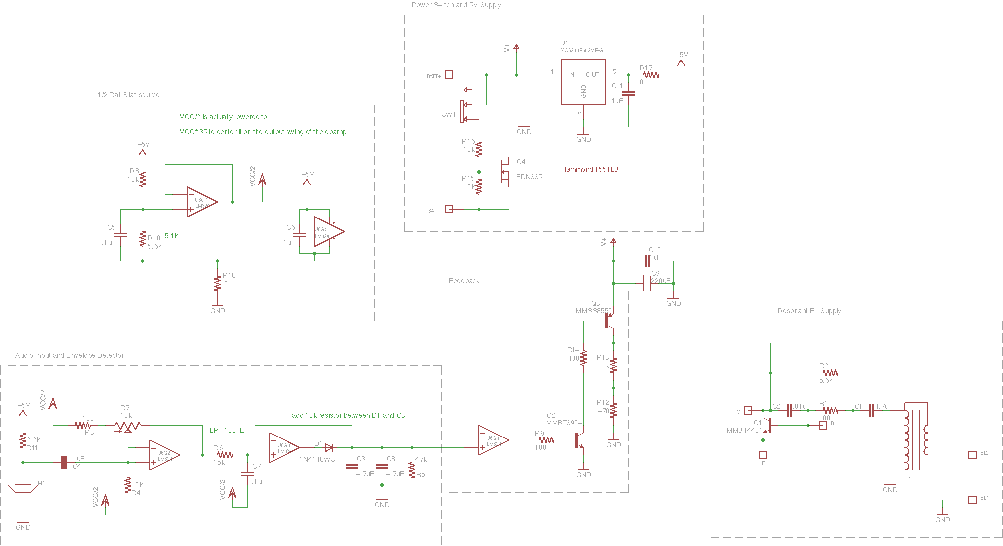
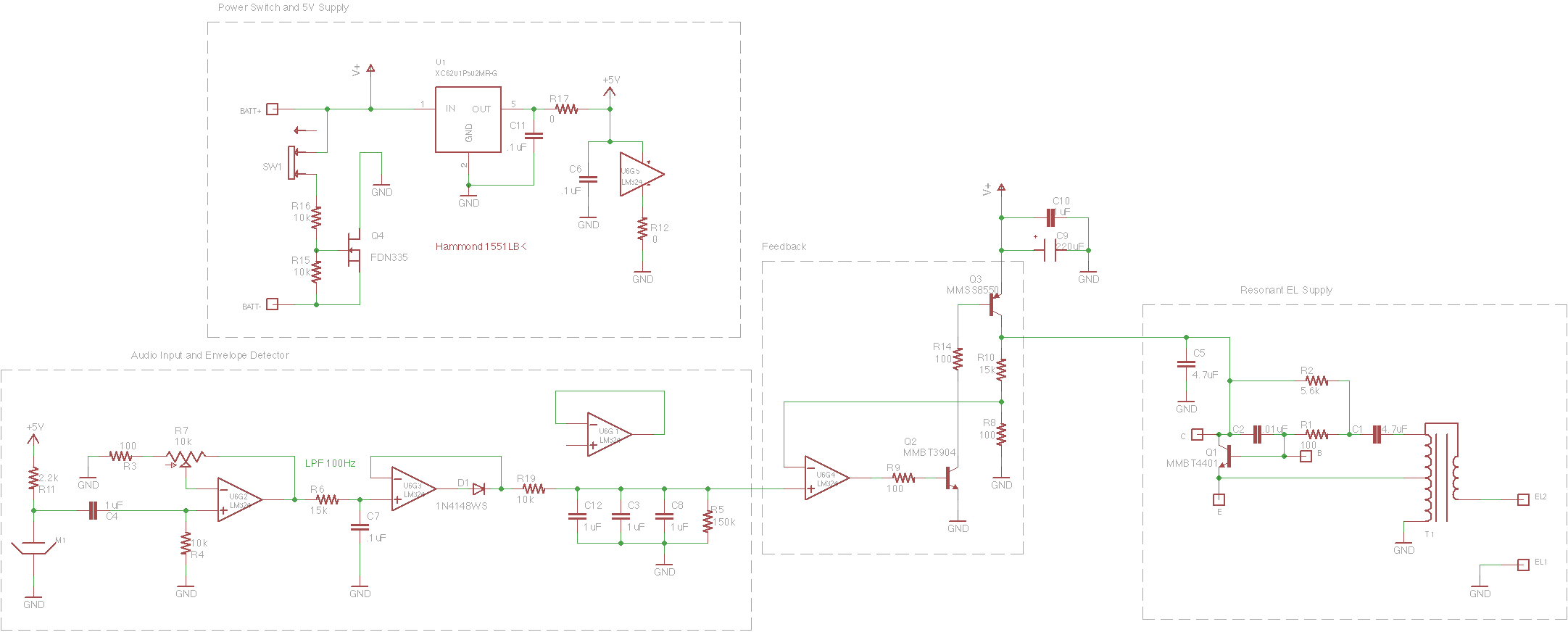
So here’s what I started out with before all the reworks:
If you’ve looked at any of my sound-reactive circuits as well as my dimming dream catcher circuit, this should look somewhat familiar.
Power Switch and 5V Supply
When I designed this thing, I was concerned that my power switch couldn’t handle the current draw of the EL panel. It’s a pretty small switch and it’s only rated for 100mA. With this configuration, the switch will only need to supply the small amount of current through R16 required to keep Q4 on which connects the circuit ground to the battery’s negative terminal.. When the switch is off, no current flows anywhere.
It’s typically a bad idea to disconnect a circuit from ground as you can have static discharge issues, but with battery power, this thing will never really be “grounded” anyway.
Also included is a simple 5V linear regulator to step down the 9V coming from a 9V battery. More on that in the next section.
Audio Input and Envelope Detector
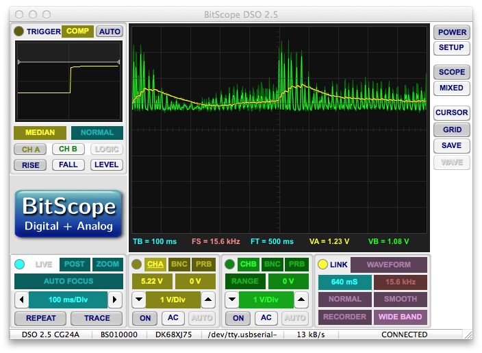
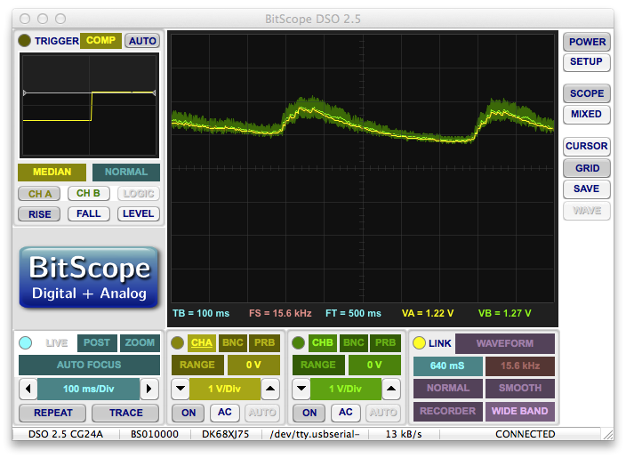
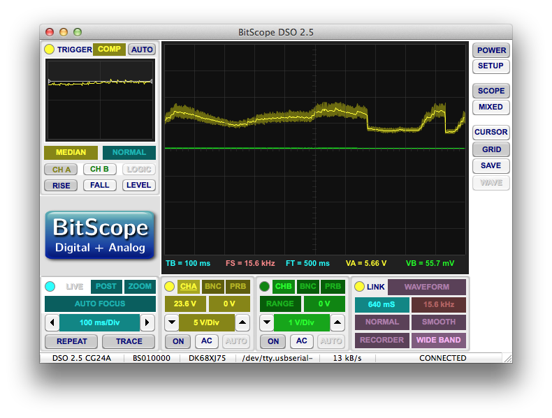
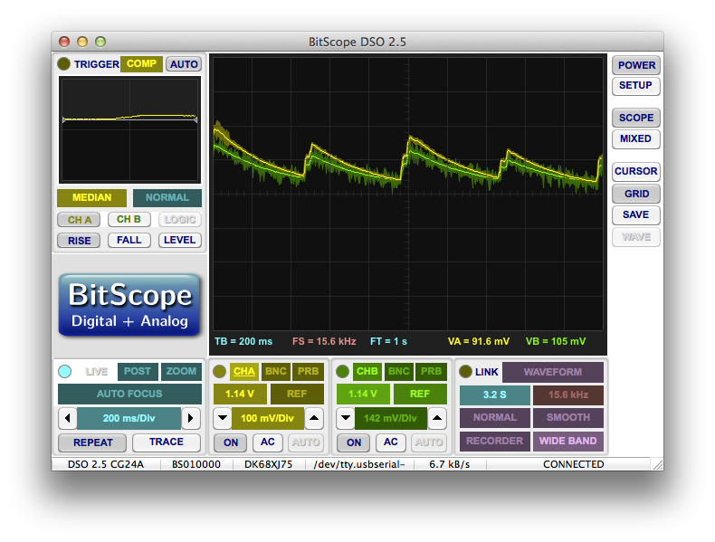
The audio signal starts at M1 (the microphone), gets amplified through a non-inverting amplifier with adjustable gain, passed through a LPF, and then an envelope follower. This should generate an output signal that is proportional in voltage to the amplitude of the audio coming into it. At least the amplitude of the audio content under 50Hz or so. Here’s a trace of the audio signal going to the envelope follower and the signal coming out:
This is ripped ripped right out of my other audio projects, so you might be able to find a more in-depth description here. The only difference this time is that I’m using a 5V source rather than driving it straight off the 9V battery. The EL transformer stage draws a significant sinusoidal current from the battery at about 2kHz, and this can easily couple its way into an audio gain stage running off the same source and cause interference. This is what happened with my latest pair of shutter shades. The 5V regulator will output a very stable 5V regardless of noise on the 9V rail, so running all of the audio stages off the 5V supply should reduce interference.
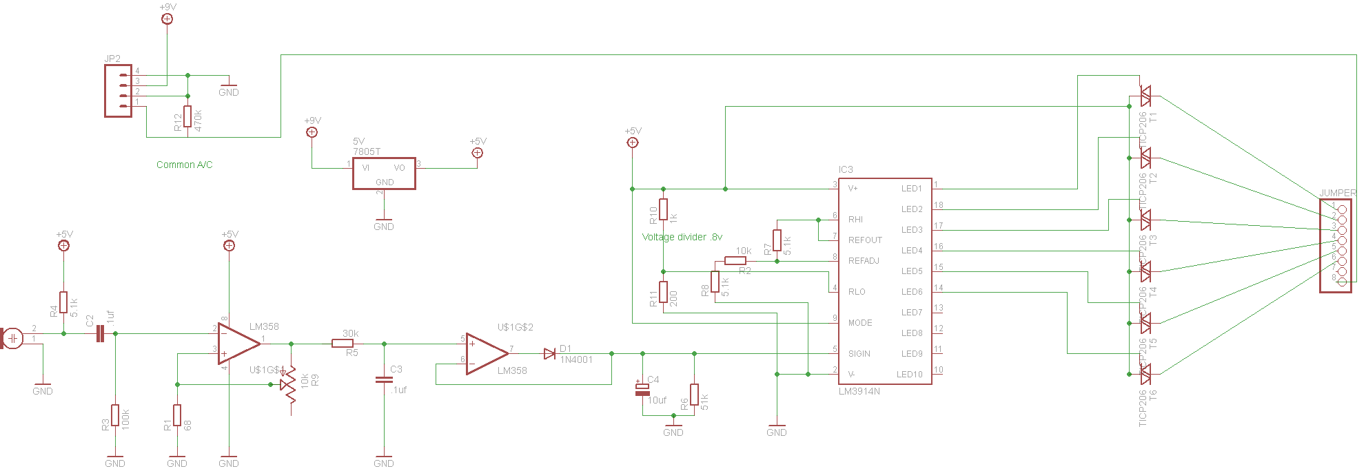
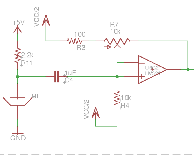
The microphone is a small condenser mic which means the same line powers it and carries the audio signal away from it. I’m not certain, but I believe that a higher voltage supplied to the mic generates a larger output signal for a given sound. The part says it can take 3-10V, but I’ve usually tried to keep my designs in the upper portion of that range (usually 9-10V). I was a little concerned that with a 5V rail, I wouldn’t have a strong enough signal coming from the mic until I saw a comment left by reader Mackenzie who had made a pair of EL glasses similar to mine. His schematic used a 5V supply on the audio rail:
And seemed to work fine:
More details here.
1/2 Rail Bias Source
This is standard practice when you need to make an audio circuit and don’t have access to a negative supply voltage. Rather than biasing the audio at ground, you can just bias it at some arbitrary voltage between 0V and your supply voltage. As long as your gain stages treat this half-rail like ground and the half-rail is stable enough, it should work just the same.
In this case, my half rail isn’t exactly half of the 5V supply. I wanted to center it around the maximum output swing of the opamps which is asymmetrical. The LM324 can output all the way to 0V, but it can only go up to 1.5V less than the supply voltage. R8 and R10 provide a voltage halfway between those limits and U6G1 buffers it to create the VCC/2 line.
Resonant EL Supply
This resonant supply is a little different than the ones I’ve made before. Because of the higher power draw of an EL panel over wire, I had to use the higher power transformer out of the store-bought supply from Ellumiglow. I made a mistake when reverse-engineering this supply in my dream catcher post. Most of the transformers I’ve been working with have a center tapped primary with three terminals and a regular secondary with two terminals. This transformer only has four terminals.
At first, I assumed that the low side of the primary and secondary were tied together (to ground) which I was going to do anyway, but was surprised to find that it was actually the high sides of each tied together.
I’m not entirely sure what the implications of this design are. Presumably, all of the current going into the EL panel also passes through the primary winding. This could potentially help with the resonant effect as increasing the current passing upwards through the primary will induce more current downwards on the secondary.
Regardless, I was stuck with the transformer, so I accommodated it in my design.
Feedback
This is the newest portion of this schematic. In the dream catcher, I drove the dimming portion of the circuit directly with the output of my signal generator. The more current I was drawing out of Q6 (Q3 in this circuit), the brighter the wire got. That wouldn’t work here for a number of reasons.
Firstly, there was the problem of inverting the signal. I wanted the panel to get bright during loud parts of the song, but a louder signal would generate a higher envelope voltage which would pull less current out of Q3 and cause the panel to actually get dimmer.
Secondly, my audio signal was on a 5V rail while I needed the dimming portion to operate on a 9V supply. This added stage also functions as a gain stage.
The basic idea is a simple double-inverter with a feedback loop made with U6G4. When the non-inverting input voltage rises above the inverting input, the output becomes more positive. This causes more current to flow into Q2’s base which in turn pulls more current out of Q3’s base. This pours more current into the resonant supply and makes the display brighter. At the same time, the voltage between R13 and R12 rises and brings up the inverting input of the opamp. When the inverting input rises above the non-inverting input, the output voltage drops and reverses the process.
This sets up the quintessential first order feedback loop for our opamp. It will try to keep its inverting and non-inverting inputs at the same voltage. Here’s a trace of the two inputs:
As you can see, they’re more or less equal.
By changing R12 and R13, the level of gain applied to the envelope signal to generate the resonant supply voltage can be adjusted. Here’s a trace of the voltage at the top of R13:
As you can see by the scale, this signal gets close to 9V, while the previous signal only goes as high as 2V. This is a result of the gain. Note that these traces were taken after I had begun changing values in the schematic, so while they reflect the general trends, they do not reflect the exact values presented in the schematic.
Circuit
If you watched my PCB etching video, this board should look familiar:
Issues
So I had a lot of problems with this circuit. I sort of anticipated that when I started and left a lot of options available (like an unpopulated collector, emitter, and base terminal around Q1), so I could tweak things as I went along. That being said, I did have some very interesting and unanticipated problems.
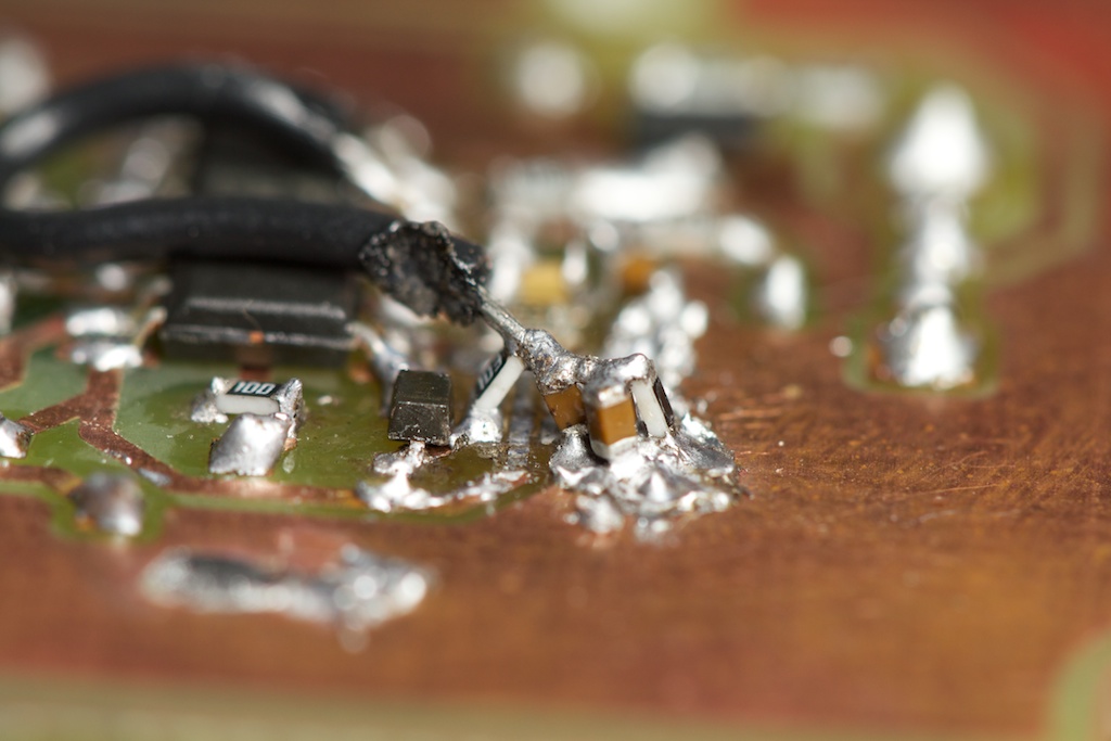
It also gave me some great opportunities to stretch my circuit reworking muscles:
I call it the “I-Fail Tower”. Or maybe some kind of reenactment of Iwo Jima.
Half-Rail Bias and High Impedance Feedback
The most obvious issue with this circuit is my choice to use half-rail audio. Half-rail would be necessary if I was trying to record or pass through audio, but because I’m using an envelope detector, I’m throwing away all of the negative audio content anyway.
For some reason, I thought that the half-rail was necessary and removing it would cause the audio signal to not make it through to the end. I’ve used this same technique before such as in the original shutter shades.
The biggest problem with this solution is that even with no audio coming in, the audio signal (and therefore the envelope) is still well above 0V. In the shutter shades, I dealt with this by changing around the resistor divider going to the comparator bank. The lowest resistor of the chain is the largest, so the entire “negative” (below the bias voltage) portion of the audio signal is dropped across that one resistor leaving the “positive” portion for all the comparators. This way a quiet audio signal (DC bias voltage) will not light up anything on the glasses.
I don’t have any comparators in this circuit, but I figured that I could play around with some of the values in my feedback stage to get the brightness output at the bias voltage to be close to zero.
I was wrong. Well, sort of. What I’d first like to point out is that had I looked at Mackenzie’s schematic a little more closely, I’d notice that he doesn’t have a negative rail and also doesn’t use a half-rail bias. And again, his works fine…
So with my half-rail bias, the brightness of the panel never drops to zero under normal operation. You can see what I’m talking about in this quick demo video I published during this stage of the project.
Now here’s the really weird part: If I turned the gain up almost all the way, the resting brightness of the panel actually went down. In theory, the resting brightness should have gone up as the higher gain amplifies any ambient noise on the line.
I’m not 100% sure what was happening, but I speculate that it all boils down to my gain stage:
As mentioned before, an opamp in a negative feedback configuration will attempt to keep its two inputs at the same voltage. We call this a “virtual short”. In normal operation, as R7 is adjusted to put more of its resistance between the output and the inverting input of the opamp, the opamp must push harder on the output to keep the two inputs at the same voltage. This results in an amplified output voltage.
This is how this stage normally operated, however when I turned the gain up very high (placing almost the whole 10k resistance of R7 in the feedback loop), I made it nearly impossible for the opamp’s output to have any affect on the inverting input. Keep in mind that an ideal opamp has the ability to output +
![]()
V to –
![]()
V, while in my real world system, I was stuck at 0V to 5V (or actually 0 to 3.5V). This incredibly high impedance and low rail voltage essentially broke my feedback loop.
Typically, when a feedback loop is broken, one of the two inputs will be driven higher than the other which will cause the opamp’s output to fly to one of the rails. In this case though, external factors held those two voltages almost equal. With the resistance of R7 being so high compared to R3, it was practically an open circuit. In that case, both inputs are more or less locked at VCC/2.
So no matter what the opamp did, the two inputs would always be at about the same voltage. It could shoot to the positive rail or just float around with no effect. Opamps aren’t really designed to be used in this sort of open-loop configuration, so their behavior is unpredictable. In the case of the LM324 that I was using, the output just slowly sank to 0V. While this might be a terrible problem in some circuits, it was actually really useful in mine allowing my panel’s brightness to actually drop to zero.
What’s even better is that the audio signal coming out of the microphone only affects the non-inverting input. That means that while the DC component of the signal is ignored, the AC component is still amplified normally. It’s sort of like using the op amp as a differential amplifier.
Again, analog has always been my weak point, but I’m fairly confident this explanation is right.
Lack of Brightness Granularity
So the video I posted above was recorded the night before I went on a week long vacation and 2 week business trip back to back. I was so excited to have anything working, that I didn’t even notice this problem until it was pointed out to me by a friend the day after.
The entire point of this project was to produce the cool pulsating dimming effect instead of a simple blink, but it seemed like any loud noise caused the panel to shoot straight up to full brightness as demonstrated in the video.
I had a suspicion that the perceived brightness output of the EL panel was not linearly related to the resonant supply’s input voltage. It could be that the brightness of the display changes more rapidly when you start feeding it higher voltage audio envelopes causing it to shoot up to the rail.
To test this, I replaced the envelope detector’s output with an adjustable power supply and measured the resulting output voltage presented to the EL panel. I came up with this plot (note that the 9V battery was partially dead for this test):
As you can see, this relationship is nearly linear.
I then wondered if the panel’s brightness was not linearly related to the AC voltage amplitude powering it. Although I was unable to produce any kind of hard data for this measurement, I did perceive a linear relationship between the brightness and voltage.
It turned out that the envelope follower was reacting way too fast to the audio signal, so rather than smoothing out a sharp increase in amplitude (kick drum), it just shot up and shot down. As you will see later, adding some more RC filters solved this problem.
Positive Feedback Loop
Due to the nature of condenser microphones and the size of my audio rails, I had another issue where noise from the 100V
![]()
2kHz output would get coupled into the input. This was the same issue I had with the strongerer glasses as mentioned before. I suspect that the 5V regulator helped, but wasn’t able to completely eliminate noise at the very high gain levels.
When gain was turned up nearly all the way (high enough to cause the output brightness to droop), then any time the panel got near full brightness (from a loud noise for example), it would produce enough electrical noise to couple on to the input. This noise would get amplified and passed through the envelope follower causing the output to rise even more. This positive feedback loop caused the panel to be locked at full brightness even after the loud noise was extinguished. The only way to return the panel to normal was to turn the gain down and then back up again.
So for a while, I had to play a game where I needed the gain up high enough to get the output to droop, but low enough to prevent the feedback loop from forming. It was a very slim margin…
Here’s a brief demonstration of these issues:
Solutions
Ground Bias
So the easiest fix was simply disconnecting VCC/2 from its opamp source and just tying it to ground. This required the gain on the feedback stage to be adjusted, but otherwise didn’t present too many problems.
Here’s the inputs to the feedback opamp after this change:
As you can see, the signal easily approaches ground.
Low Pass Filter
I made some changes to the envelope follower stage to combat the granularity problem. C12, C3, C8, R19, and R5 are the compadres making up the I-Fail Tower. I’m not certain if all of these changes are still required as the actual RC constant of that portion of the circuit hasn’t really changed significantly. They may have just been implemented to fix interim problems.
One significant change is the inclusion of R19. I think originally it was there to act like a voltage divider with R5 and cut down the signal going to the next stage for some forgotten purpose, but it doubles as a low pass filter on the envelope itself. Basically, it slows down the rising edge of any spike in volume giving you a more gradual, better looking rise in brightness.
The downside is that the brightness peak will no longer coincide exactly with volume peak but instead come slightly after. This time-lag is perceptible, but not too distracting if you’re not looking for it. I might take that resistor out in future versions or at least lower it some to prevent that from being a problem.
Reduce Feedback
This solution isn’t really even a solution. Since I no longer had to increase the gain to lower the resting panel brightness thanks to the removal of VCC/2, I could now operate the device at lower gains. Lower gain means that it needs a louder audio signal to operate, so I just turned the volume up on my speakers and placed the device closer to the speaker diaphragm. Considering this thing is meant to be used at a concert, this shouldn’t be a problem for the user.
Regardless, I’ll try to see if I can implement better feedback reduction in future versions at least so I can test the thing without pissing off the neighbors.
Demo
So there isn’t a whole lot to this demo. I just played a song and recorded it doing it’s thing. It wasn’t until right about the time of this recording that I realized that the panel was doing precisely what I was trying to get it to do almost eight months ago. If you notice the table or camera shake at all, it’s because I was dancing like an idiot right out of frame.
I’m comparing it to a tea light candle so you can get an idea of how bright it actually is (something that is portrayed poorly over camera).
Conclusion
As per ch00ftech tradition, nothing is easy. I’m glad that I finally got it working though. I’m a little bummed that the actual mechanism for dimming had to be more or less stolen from a store-bought solution, but I think I added enough to consider this an original project.
The prototype is incredibly ugly, but at least it functions correctly. I’ll be remaking the circuit before sending it off to my client (if he still even remembers me), so expect one small update at some point in the future showing off the polished product.
I also really want to try testing this driver alongside the original. For starters, it’s about 1/10th the size and weight…
Continue the story here.




Pingback: Months of failure lead up to this EL panel dimmer that pulses to the music
What are C B and E in the schematic?
Those are the “unpopulated collector, emitter, and base terminal” I was referring to. They’re just open test-points left in in case I needed them.
ah, thanks, serves me right for not reading more carefully!
You’ve repeated a paragraph right at the end.
“I’m a little bummed that the actual mechanism for dimming had to be more or less stolen from a store-bought solution, but I think I added enough to consider this an original project.”
Great write-up as usual. Love the detail, and they’re proving extremely useful for my course. Extremely academic, waaay too little practical stuff. We don’t even get a lab for outside use.
Oh well, wrong university.
Whoops. Good eye! It should be fixed now.
Thanks for the kind words, I’m glad you like my blog.
Pingback: Can I get this thing off my desk now? | ch00ftech Industries
Pingback: EL Dimmer Circuit Questions | ch00ftech Industries
Pingback: Dimming EL Wire Dreamcatcher | ch00ftech Industries
Given your talents with microcontrollers, I’m curious as to whether you had considered dimming the EL Wire using PWM. I know your earlier experiments with triacs didn’t pan out but I wondered if you had thought of using a high frequency driver signal (e.g. 2kHz) and a lower frequency PWM signal (50Hz) to dim the wire. Effectively ‘bursting’ the high frequency signal for varying amounts of time but still fast enough that the eye wouldn’t notice (just like you’d dim an LED). Did you try it? Do you think it would work?