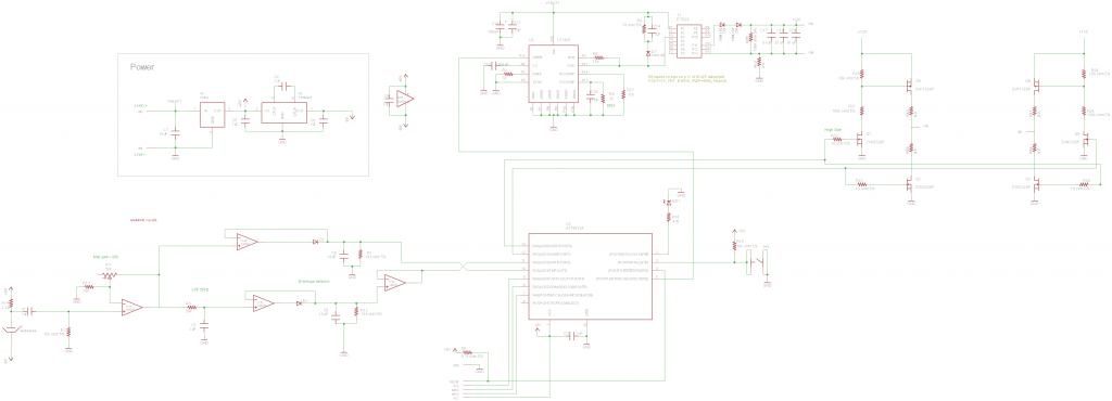
Schematic
Now let’s get down to the nitty-gritty of my design.
Audio stuff
Because my audio circuit is borrowed so heavily from my DJ jacket, I won’t waste any time talking about it here except to say that I gave my micro controller two inputs: one for the envelope of the audio passed through a 50Hz LPF and one for the audio envelope with no filter. This would give me more versatility in how it reacts to sound.
Class D Implementation
If you remember reading about my windshield wiper motor driver, I was very careful to avoid the use of P-type FETs as they are expensive and very inefficient. I also took care to drive the gates of all of my FETs very hard to improve efficiency at higher switching frequencies.
What I realized when designing my Class D in this circuit is that:
- My switching frequency will be much lower, so switching losses are negligible.
- My currents are tiny (maybe 10mA or so), so there is no need to worry about using PFETs which aren’t that much different from NFETs at lower currents.
I still did need some way to drive the gates of the high-side PFETs low. Typically, you would have a pull up resistor on the high side and something (FET, micro controller pin) pulling down on the low side. The only problem is that the high side is at 120V, and the maximum gate-source voltage is listed in the data sheet as 20V so pulling the gate to ground would blow the FET. The resistor divider on the gates keep this voltage from getting too low.
To prevent shoot-through issues (turning high and low side FETs on simultaneously), I controlled the high side and low side FETs manually with two different micro controller pins and added a small amount of delay in firmware.
Flyback Controller
If you haven’t figured it out by now, my flyback controller IC is definitely overkill for this project. The part is designed for high precision and low noise operation, and EL wire requires anything but. No wonder it’s a six dollar chip on Digikey.
So if you’re wondering about some of the resistor values, I recommend pouring over the data sheet. I just picked some values that seemed to work okay ignoring a lot of the advanced features such as “load compensation” that this part has.
Snubber
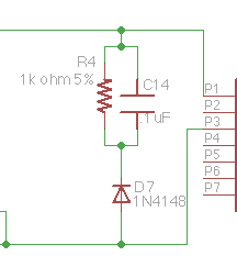
You might be wondering what D7, R4, and C14 are doing. If you remember from before, there is some leakage inductance on the transformer that will store some energy and then dissipate it back into the primary circuit just like any normal inductive load. This energy can damage components on the primary side, so it’s important to do something about it.
The usual solution for an inductive load like this is to just add a flyback diode, but that won’t do here. The diode will offer too low of an impedance to both the leakage inductance and the main inductance in the transformer core. Adding it will cause some (if not all) energy that is meant to go to the output to dissipate through this diode.
The solution is to build a “snubber”. This diode, resistor, capacitor configuration provides an easy path for the sharp pulse of current coming from the leakage inductance while blocking the larger pulse stored up in the transformer.
Sizing this resistor and capacitor pair isn’t exactly straightforward. You need to size them so that they present a low enough impedance to safely dissipate the flyback inductance, but high enough to prevent the magnetization inductance from doing the same. One way to accomplish this is to think of the RC pair as a voltage supply. Because they will act as a low pass filter, the voltage across them can be relatively constant. We can actually model them as a voltage supply:
So, departing from the resistor and capacitor for the time being, we can consider what we want
![]()
to be. This is a little complicated because we want it to be higher than the magnetization inductance’s flyback voltage. It might not be directly apparent, but if you work out the math, the magnetization current dissipating in the secondary winding is equivalent to it dissipating in the primary at 1/20th the voltage (due to our turns ratio). So, if our coil’s output to the secondary is nominally 120V, our nominal output to the primary would be 6V. We need to make sure that
![]()
is larger than 6V.
On the other end, note that the larger
![]()
is, the more instantaneous current will flow through your snubber (V = IR; higher V = higher I). You don’t want to blow up any components on that front, so let’s just say that
![]()
. Keep in mind that we’re ignoring the forward voltage of the diode for these calculations for simplicity. High precision isn’t required for sizing these components. It will probably be less than a volt anyway.
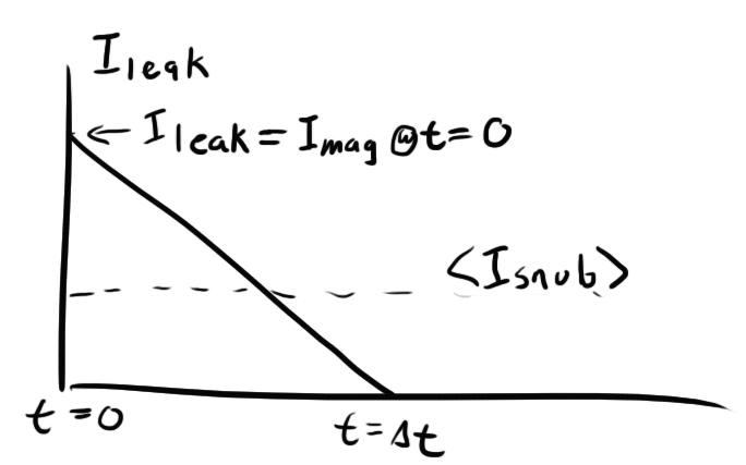
As soon as the switch on the transformer opens, the current through the leakage inductance will start at it’s initial value (equal to the magnetization current) and start to ramp down linearly with a slope proportional to the
![]()
:
![]()
![]()
So let’s work out our
![]()
. I determined before that
![]()
is 166mA, so the peak current (at t=0) will be twice that. I also measured
![]()
at 6.3
![]()
H
![]()
![]()
![]()
At 285kHz, our period is about 3.5
![]()
s, so this discharge time is more than fast enough to dissipate the leakage inductance before the next cycle begins.
Now that we have this all worked out for
![]()
, we need to step back and find our RC. The R will be what actually dissipates all the energy, so we can equate the power loss through
![]()
with the power loss through
![]()
. The power loss through
![]()
is
![]()
.
In order to get
![]()
, we need to take the area under the slope above to find total charge moved per cycle and then divide it by the period to get current:
![]()
![]()
Now we can solve for power dissipation and set it equal to the dissipation through
![]()
:
![]()
Remembering our definition of
![]()
and that we set
![]()
to twice
![]()
:
![]()
![]()
![]()
![]()
I opted to round up to a 1k resistor for simplicity.
Now we have to choose the capacitor. The cap is easy. Its goal is to stabilize
![]()
and keep it relatively constant. To do this, we just need to pick
![]()
such that the RC time constant of the snubber is at least 5-10 times the period of our switching frequency.
![]()
![]()
![]()
![]()
![]()
F. There’s no danger in going higher though, so I chose .1
![]()
F for safety.
Dual Diode
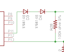
You might also be wondering why I have two series diodes rectifying my flyback converter. Remember that my flyback converter is going to be stepping up to around 120V, so I need a rectifier that is rated for at least 120V (more like 150 for safety). Originally, I was using a badass 2A, 150V diode, the SS2150-LTP. When I used this single diode, I found that it worked perfectly fine at giving me my output voltage, but it heated up a LOT in the process. I couldn’t comfortably hold my finger on it for more than a few seconds (also had to be careful not to shock myself in the process).
Curious about why this was, I took a better look at the data sheet, I found that my diode has 170pF of junction capacitance. Junction capacitance is a property of semiconductor junctions that determines how much current is required to turn the junction “on”. I dealt with the gate capacitance of FETS in my windshield wiper motor. In that case, I had to be careful to supply a lot of current to the gate in order to get my FET to go from the full on to full off state quickly to prevent resistive losses in the intermediate stages.
Similarly, I need to prevent my diode from being half on. This is especially important given how high my output voltage is. If even a single mA leaks through my diode, I’m looking at close to an eighth Watt of power dissipation.
To solve the problem I was having, I decided to move to using two lower-voltage diodes with much lower junction capacitances in series. I chose the 1N4148 which has a junction capacitance of just 4pF. These diodes are also rated for a much lower current, but considering how little current is passing through my secondary winding, I’m not too concerned about exceeding their ratings.
The SS2150 is still a good diode though. It’s just likely not made for 285kHz operation. It might be more comfortable with something like 60Hz.
Firmware
The firmware for my circuit utilizes a software interrupt of the ATTiny24 to generate the waveform going to FETs. Because I had to manually add delay between turning the one side off and the other on, this interrupt does not control the pins directly but rather calls a short interrupt routine that swaps them with the appropriate delays.
Configuration
DDRB = 0X05;   //Configure ports
PORTB = 0X05;
DDRA = 0XF3;
OCR1A = 0x7F;  //How high timer counts
TCCR1A = 0x00; //no output, mode 4 (clear timer on compare)
TCCR1B = 0x0A; // 1/8 timer prescale
TIMSK1 = 0x02; //enable compare match interrupt.
TCNT1 = 0;     //set timer count to zero
ADCSRA = 0b10000000; //enable ADC
ADCSRB = 0b00010000; //left justified bits out of ADC
sei();
The timer is configured in 16 bit mode so that it gives me a large range of values to work with for frequency. The micro controller will start a count at 0 and count up to OCR1A where it will run my interrupt routine and reset the timer. The higher OCR1A, the longer the delay between interrupts and the lower the frequency.
I also left-justified the bits coming out of the 10-bit ADC so that I can just use the high byte and throw away the low two bits.
The main loop of my code just takes a value from the ADC and converts it to the appropriate timer counter every 5ms:
for(;;){
   ADMUX = 0b10000010;            //Select proper port
   ADCSRA|=0b01000000;            //START CONVERSION
   while((ADCSRA & (0b01000000))) //WAIT FOR IT TO FINISH
   ADCSRA|=(0b00010000);          //CLEAR FLAG
   uint16_t temp = 2048-(ADCH<<3);//Convert and store timer value
   nextvalue=0x7f+(temp);
   _delay_ms(5);
}
Originally, I had this loop set OCR1A immediately, but I ran into a problem where sometimes it would set OCR1A to a value that was lower than the current timer count. This means that the timer would have to count all the way to 0xFFFF and loop back around to OCR1A before the interrupt was run This would cause a huge delay.
I fixed this problem by only setting the new OCR1A during the timer interrupt where the timer count is getting reset anyway:
ISR(TIM1_COMPA_vect)
{
   //swap pins
   if (on)
   {
      PORTA = 0X00;
      PORTA = 0X01;
      on = 0;
   }
   else
   {
      PORTA = 0X00;
      PORTA = 0X02;
      on = 1;
   }
   OCR1A = nextvalue;  //set next counter value
}


yea there is a MUCH MUCH easier way to do this..
you take the standard inverter and the el panel and put a CDS photocell in series then take a standatd lm328 amplifier and hook the output to a bicolor LED and shine that on the photocell
DONE! i can give you schematics and stuff if you want
So you’re just talking about putting an adjustable resistance in series with the EL panel? I suppose that would work, but it’s not the most efficient way to do it.
Also, looking at a few datasheets, the maximum power dissipation though a CdS cell is around 100mW. If I were to use one on a panel, it might need to dissipate upwards of 7-800mW. It couldn’t take the heat. I suppose you could put a few in series, but that’s going to get pretty messy.
This solution might work in smaller loads like short EL wires though. Thanks for the tip!
When I first read your comment above I thought you were using the photocell to read the light from the EL panel and then reverse the voltage polarity when it detected maximum brightness, which should generate AC that would self-regulate to the right frequency to sustain that brightness level. But then when you mentioned LEDs you lost me! But would a feedback control mechanism like what I thought you meant actually work?
Matthew was recommending using a optoisolator as a variable resistance. The idea is that you could control current from a low-voltage circuit and not have to worry about the 120V blowing anything up.
You present an interesting idea, but I think it would end up being more trouble than it’s worth. The EL panel is a fairly “slow” material. It takes a few milliseconds for it to react to changes in current, so using its brightness in some kind of feedback system would prove difficult. To say nothing of the wiring/mechanical complications this would create.
>> I chose the 1N4148 which has a gate capacitance of just 4pF.
Not gate. Junction.
Since you were ordering from Digi-Key anyway, you could have purchased some BAT-41 Schottky diodes (19,000 in stock) . The BAT-41’s capacitance is 2pF, half of the 1N4148’s capacitance, and its forward voltage at 20mA forward current is 0.30 volts per diode, significantly less than the 1N4148’s 0.95 forward volts per diode.
Whoops, typo. Thanks.
I figured out my diode problem after I already made my order, so I had to use what I had on hand. Next time I’ll be sure to choose more wisely. Thanks for the tip!
while pouring over various patents on zinc sulfide phosphors i discovered reference to the color shift in el wire, my 555 based driver was a quick and dirty means of observing it myself and as an excuse to learn something about driving el wire… more of a first attempt using spare parts before devoting more time to designing a proper circuit rather than basing it off some simple dc to ac inverter circuit i found in the internet
along with the brightness being a function of frequency i found voltage had a similar effect but would cause the el wire to age faster than driving at a higher frequency would, and yes driving at higher voltages also caused my salvaged transformers to overheat and leak paraffin wax everywhere
Oh by all means, I think it’s great what you did, and it really helped me in my initial research! I was just making a point that in general, there aren’t too many resources available on EL wire and driving it properly.
there really arent, i had to resort to reading dozens of white papers and patents to figure everything out, my result was a working driver that was extremely inefficient, occasionally overheated and administered ~130 volt shocks when i wasn’t paying attention
ive also been working out some ideas on mixed frequency driving el wire to increase lifespan while making it brighter by rapidly switching between low and high frequencies at a rate where it would be brighter while impacting lifespan al little as possible
I also noticed the frequency shift.
Wonder if this effect can be used to make a variable spectrum microscope light?
For certain applications this would be handy indeed as if the wavelength shift is linear then you could image a sample at a range of multispectral frequencies rather than green or blue.
I like the Supertex HV852 for this as it draws under 5mA with small wires allowing a PIC to directly drive it and adjust frequency with a single drive lead and a capacitor.
So one 12F683 can run six separate EL wires, with Charlieplexing even more.
as far as i have observed there is only a single color shift at ~2000 hertz and i have not found any information to indicate there any more
it is far from linear and im not sure the amount of light would be sufficient for a microscope anyways
Pingback: Revisiting the EL Panel and the True Meaning of RMS | ch00ftech Industries
Pingback: Naw But Really Though…How Do You Power An EL Panel? | ch00ftech Industries
Pingback: I Should Give China More Credit | ch00ftech Industries
Pingback: The Color Mixing Christmas Light Project » Blog Archive » Pixel Mapping a Jogging Jacket
Pingback: Dimming EL Wire Dreamcatcher | ch00ftech Industries
Pingback: Sound Reactive EL Panel Dimmer (for real this time) | ch00ftech Industries
Pingback: Months of failure lead up to this EL panel dimmer that pulses to the music
Pingback: Months of failure lead up to this EL panel dimmer that pulses to the music | Daily IT News on
Pingback: Can I get this thing off my desk now? | ch00ftech Industries
Pingback: Soil Moisture Sensor | ch00ftech Industries
Pingback: More EL panel / el driver / el inverer hacking – pulsing | Reactive Lights
I found a great source for the EL panels. http://www.etsy.com/shop/lightkraft I looked all over and they are the least expensive in the US.. Most of their prices include the inverters (which are matched to each panel). Another good source is EL-WORKS http://www.el-w.com
Pingback: Bucking It Up » Geko Geek
https://ch00ftech.com/wp-content/uploads/2012/05/flyback11.png
Just saying, #schematicsthatlooklikefaces
What’s your take on this method?
http://www.enactiveenvironments.com/enabling/pwm-and-electroluminescent-smooth-dimming/
Hi,
How can I contact you? Email
Just click the email button at the top of the page!